Chapter 2 Robot Parameters
In Chapter 1, we explored the product's selling points and design concepts, providing you with a panoramic view of the product's high-level understanding. Now, let's move on to Chapter 2 - Robot Parameters. This chapter will be the key to your understanding of the product's technical details. A detailed understanding of these technical parameters will not only help you fully realize the advancement and practicality of our products, but also ensure that you can use these technologies more effectively to meet your specific needs.
1 Robot Specifications
1.1 Robot Arm Parameters
| Indicators | Parameters |
|---|---|
| Name | Little Elephant Collaborative Robot Arm |
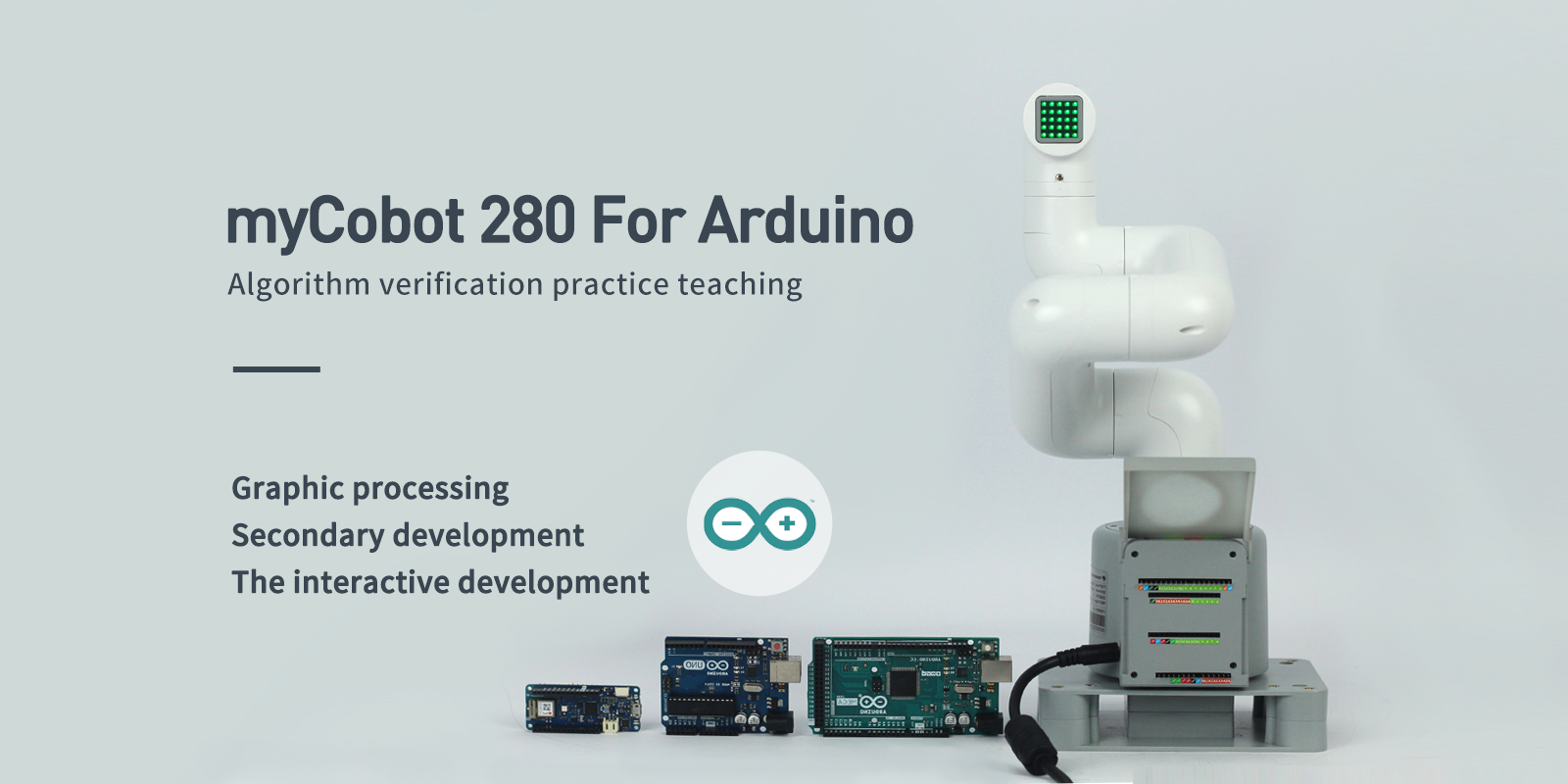
| Model | myCobot 280 Arduino 2023 |
| Degrees of Freedom | 6 |
| Payload | 250g |
| Working Radius | 280mm |
| Weight | 860g |
| Power Input | 12V,5A |
| Working Temperature | -5-45℃ |
| Communication | USB (depending on the development board) |
2. Control Core Parameters
| Indicators | Parameters |
|---|---|
| SOC | None |
| CPU | None |
| Bluetooth/Wireless | None |
| USB | None |
| Display | None |
| HDMI interface | None |
| Custom buttons | None |
| IO interface | Panel IO is a transfer function, depending on the expansion board |
3. Structural size parameters
3.1 Workspace
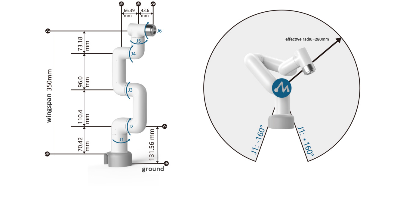
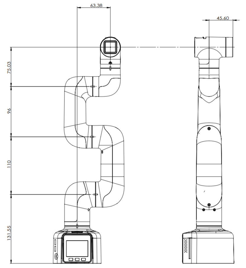
3.2 Specifications
3.3 Joint motion range
Note: ⚠ This joint limit information function is only available on Atom firmware ≥ 7.3 and pymycobot library ≥ 4.0.2.
| Joint | Range |
|---|---|
| J1 | -168 ~ +168 |
| J2 | -140 ~ +140 |
| J3 | -150 ~ +150 |
| J4 | -150 ~ +150 |
| J5 | -155 ~ +160 |
| J6 | -180 ~ +180 |
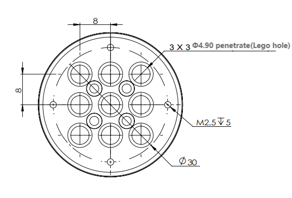
3.4 Hole Installation
- The robot base is mounted with a flange. The base is compatible with both LEGO technology parts and M4 screws.
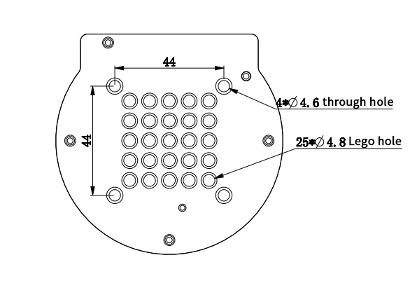
- The robot end is mounted with a flange. The end of the robot arm is compatible with both LEGO technology parts and screw threaded holes.
4. Electrical characteristic parameters
Electrical interface of the robot arm
4.1 Introduction
Base
- A. The interface on the front of the base is shown in Figure 2.1.8.2-1:
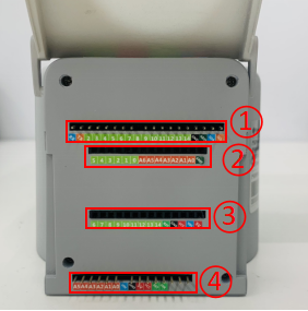
Figure 2.1.8.2-1 Front interface of F base
- ① Function interface group 1
- ② Function interface group 2
- ③ Function interface group 3
④ Function interface group 4
B. The interface on the top of the base is shown in Figure 2.1.8.2-2:
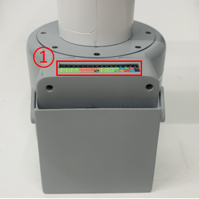
Figure 2.1.8.2-2 Interface on the base
- ① Function interface group 5
- C. The interface on the right side of the base is shown in Figure 2.1.8.2-3:
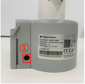
Figure 2.1.8.2-3 Interface on the right side of the base
- ① Power DC interface
Base interface description
Note: The functional interface groups are all 2.54mm DuPont interfaces, and 2.54mm DuPont wires can be used externally.
A. Figure 2.1.8.2-4, Figure 2.1.8.2-5, Figure 2.1.8.2-6 and Figure 2.1.8.2-7 are the signal names of the four expansion interface groups on the front of the base. These interfaces are used to connect different Arduino development boards. Function interface group 1 and function interface group 4 can be used to expand development boards with the same pins as Arduino UNO, such as: Arduino UNO, Arduino MEGA 2560, etc.; Function interface group 2 and function interface group 3 can be used to expand development boards with the same pins as Arduino MKR WiFi 1010;

Figure 2.1.8.2-4 Function interface group 1

Figure 2.1.8.2-5 Functional interface group 2

Figure 2.1.8.2-6 Functional interface group 3

Figure 2.1.8.2-7 Functional interface group 4
B. Figure 2.1.8.2-8 It is the signal name of the functional interface group on the base. This part of the interface corresponds to each functional interface of the connected Arduino development board.

Figure 2.1.8.2-8 Functional interface group 5
C. Power DC interface: Use a DC power socket with an outer diameter of 6.5mm and an inner diameter of 2.0mm; use the 12V 5A DC power adapter provided by the manufacturer to power myCobot 280.
4.2 Electrical interface of the end of the robot
Introduction to the end of the robot
- A. The end of the robot is shown in Figure 2.1.8.2-9 and Figure 2.1.8.2-10:
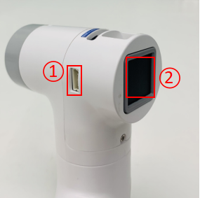
Figure 2.1.8.2-9 End of the robot
- ① Servo interface
- ② Atom
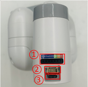
Figure 2.1.8.2-10 End of the robot
- ① Function interface group 6
- ② Grove
- ③ Type C
Terminal interface description
- A. The definitions of each interface of functional interface group 6 are shown in Table 2.1.8.2-1:
| Label | Signal name | Type | Function | Remarks |
|---|---|---|---|---|
| 5V | 5V | P | DC 5V | |
| GND | GND | P | GND | |
| 3V3 | 3V3 | P | DC 3.3V | |
| G22 | G22 | I/O | GPIO22 | |
| G19 | G19 | I/O | GPIO19 | |
| G23 | G23 | I/O | GPIO23 | |
| G33 | G33 | I/O | GPIO33 |
Note:
I: Input only.
I/O: This function signal includes input and output combination.
When the tube angle is set as the output end, it will output a voltage of 3.3V.
The pull current of a single tube angle decreases with the increase of the number of pins, from about 40mA to 29mA.
If a GPIO is set to output mode, it outputs a high-level signal, and the circuit connection is shown in Figure 2.1.8.2-11, and the LED light will light up.
Figure 2.1.8.2-11

B. Type C interface: can be used to connect and communicate with the PC end and update the firmware.
C. Grove: Definition as shown in Figure 2.1.8.2-12

Figure 2.1.8.2-12 Grove
D. Servo interface: used for end extension gripper, currently supports matching adaptive gripper.
E. Atom: used for 5X5 RGB LED (G27)Display and key functions (G39)
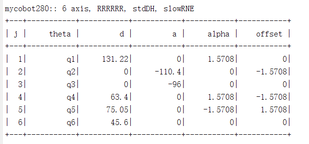
5.DH parameters
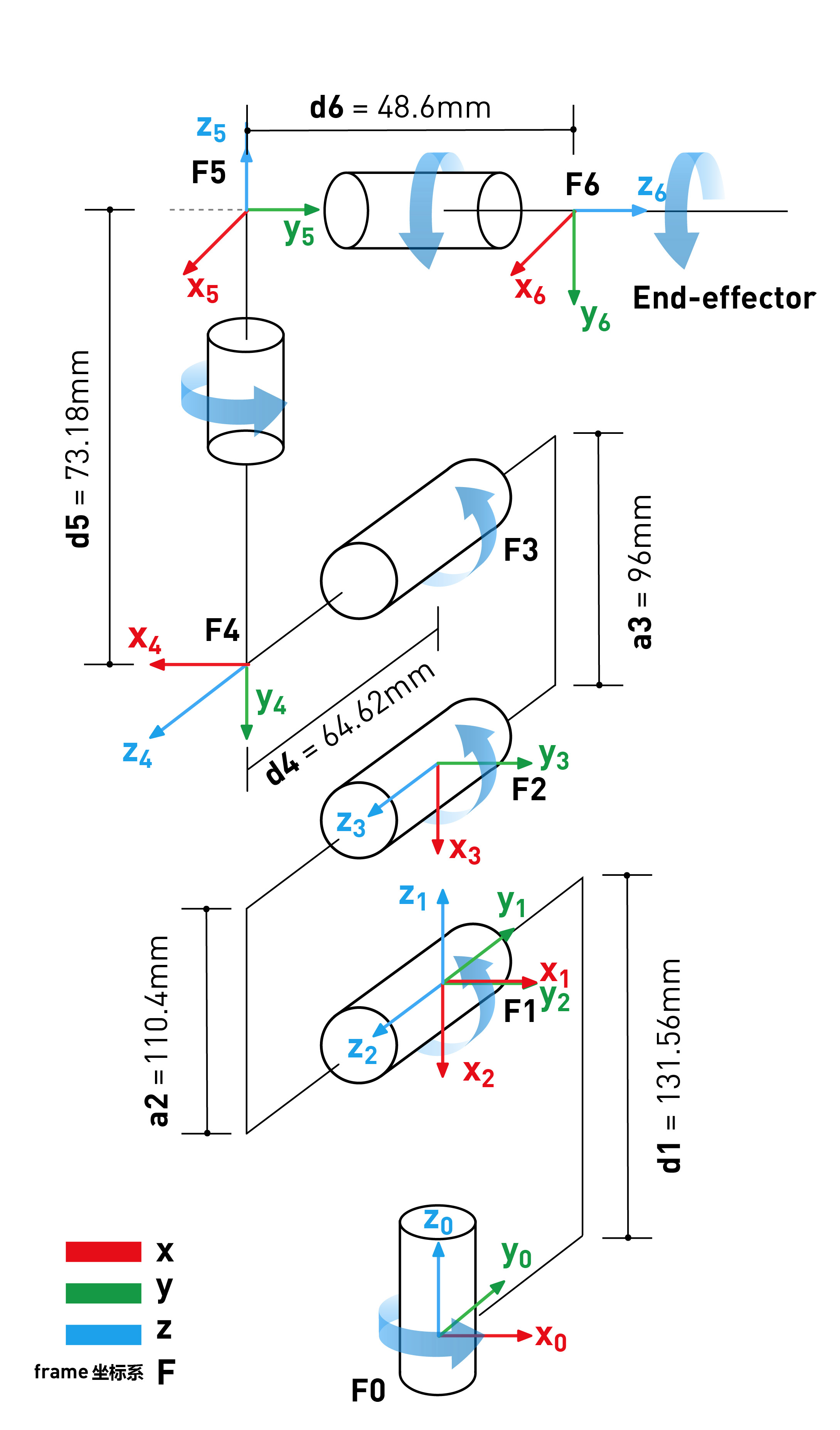
SDH parameter table: