280 PLC IO interactive control case
1 Functional effect description
After the robot receives the IO signal from the PLC, it will perform an action to return each joint to zero position
2 Principle description
Since the input and output of the robot is 3.3V and the input and output of the PLC is 24V, a 5V relay and a 24V relay are required. The output end of the robot will first output a signal to energize the 5V relay coil, connect the normally open contacts, and pass the 24v signal to the input end of the PLC. After the PLC collects the input signal, the PLC output end will output a signal to energize the 24v relay coil, connect the normally open contacts, and pass the 3.3V signal to the input end of the robot. After the robot collects the input signal, it will perform an action to return each joint to zero position
3 Hardware link
Overall connection diagram
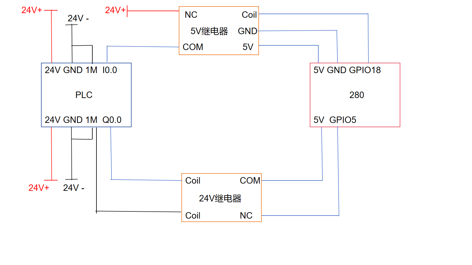
Wiring of robot input and PLC output
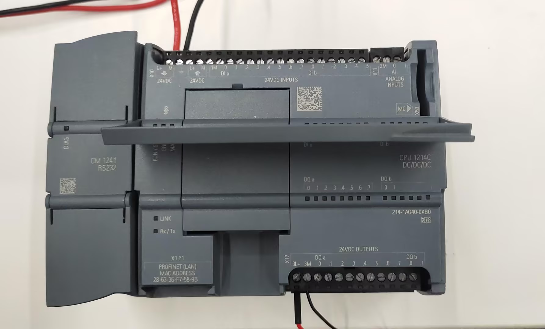
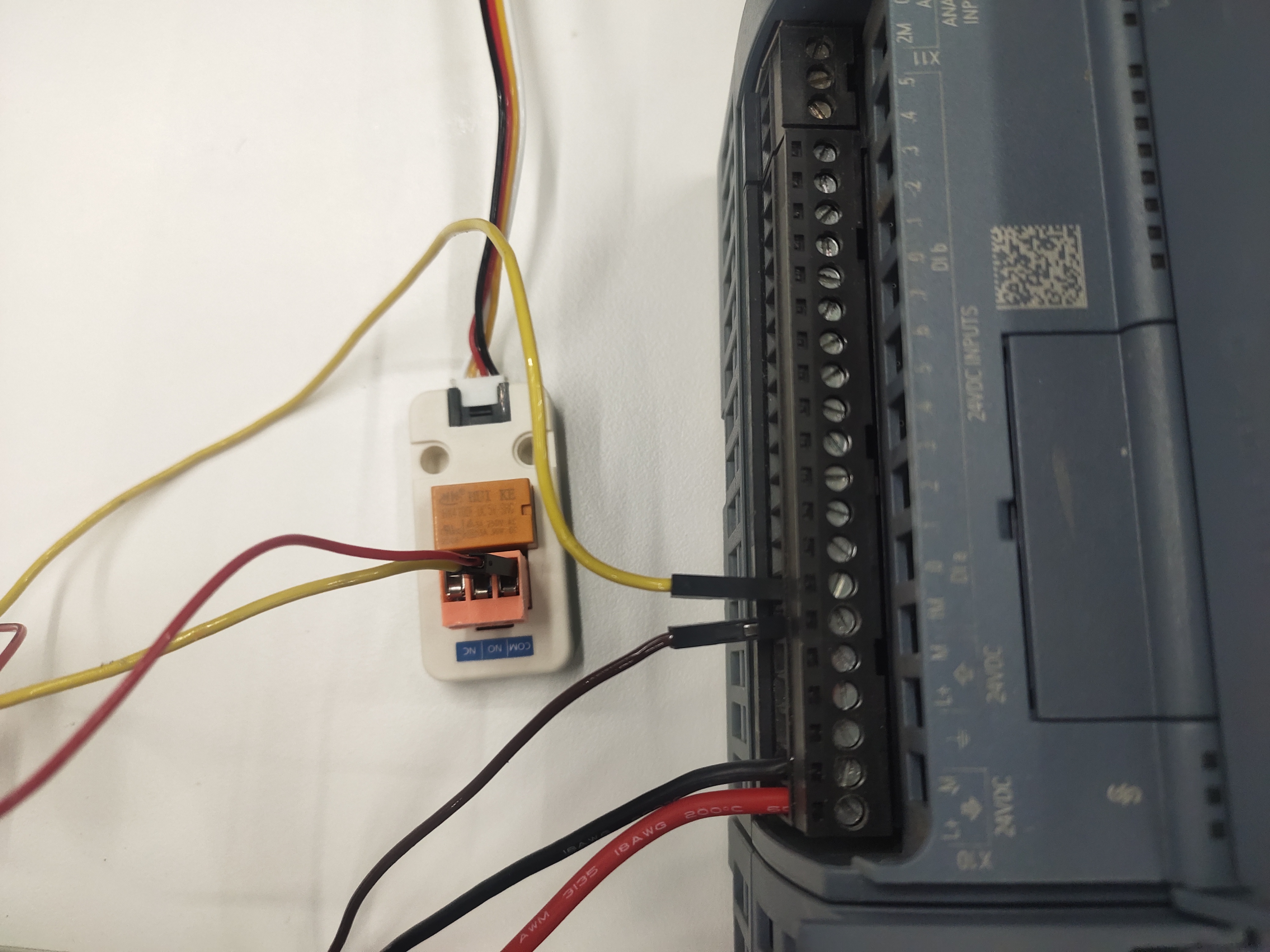
First connect the PLC to a 24V power supply
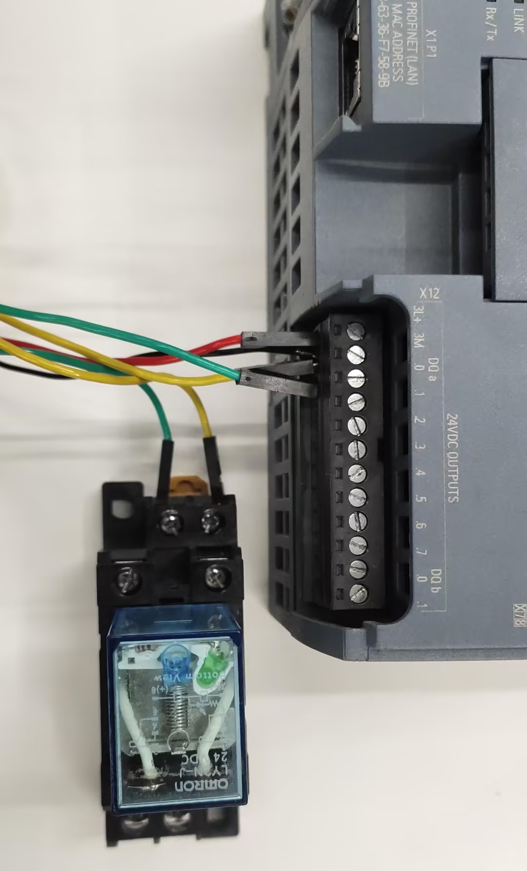
Then connect the PLC output to the 24V relay coil
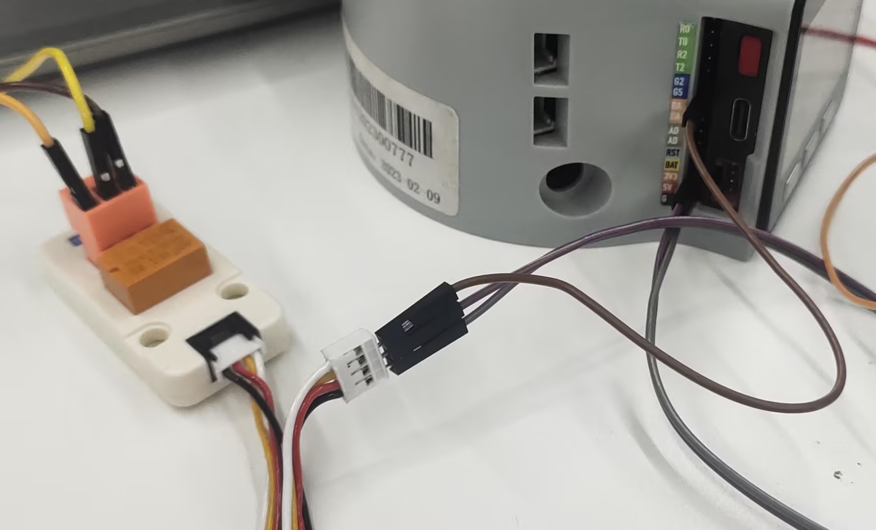
Connect the robot's GPIO2 and 3.3V to the normally open contact of the 24V relay !
Wiring the output of the robot and the input of the PLC
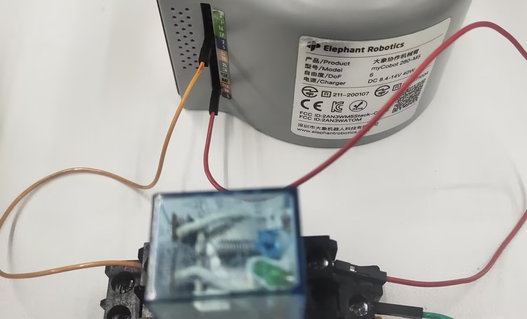
Connect the 5v, GND and GPIO5 of the robot to the coil of the 5V relay
Then connect the positive pole of 24V to the COM terminal of the 5V relay, the negative pole of 24V to the 1M terminal of the PLC, and NO to the input of the PLC
4 Software Programming
Robotic Arm Program
from pymycobot import MyCobot280
import time
mc=MyCobot280("COM6")
mc.set_basic_output(5,1)
while 1:
if mc.get_basic_input(2)==1:
mc.sync_send_angles([0,0,0,0,0,0],50)
break
else:
pass
mc.set_basic_output(5,0)
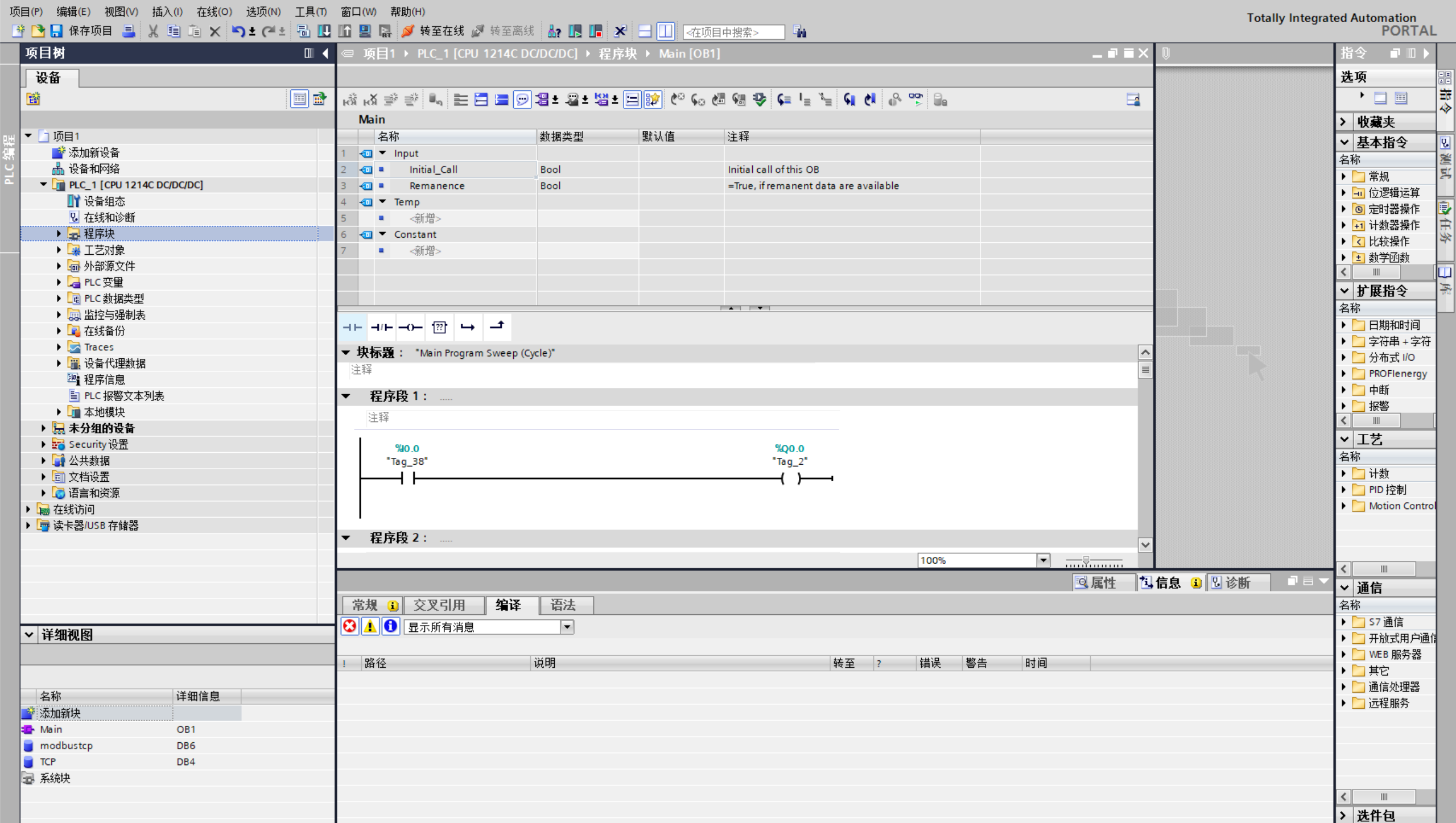
PLC Program
5 Effect Display