Suit building
Installation video
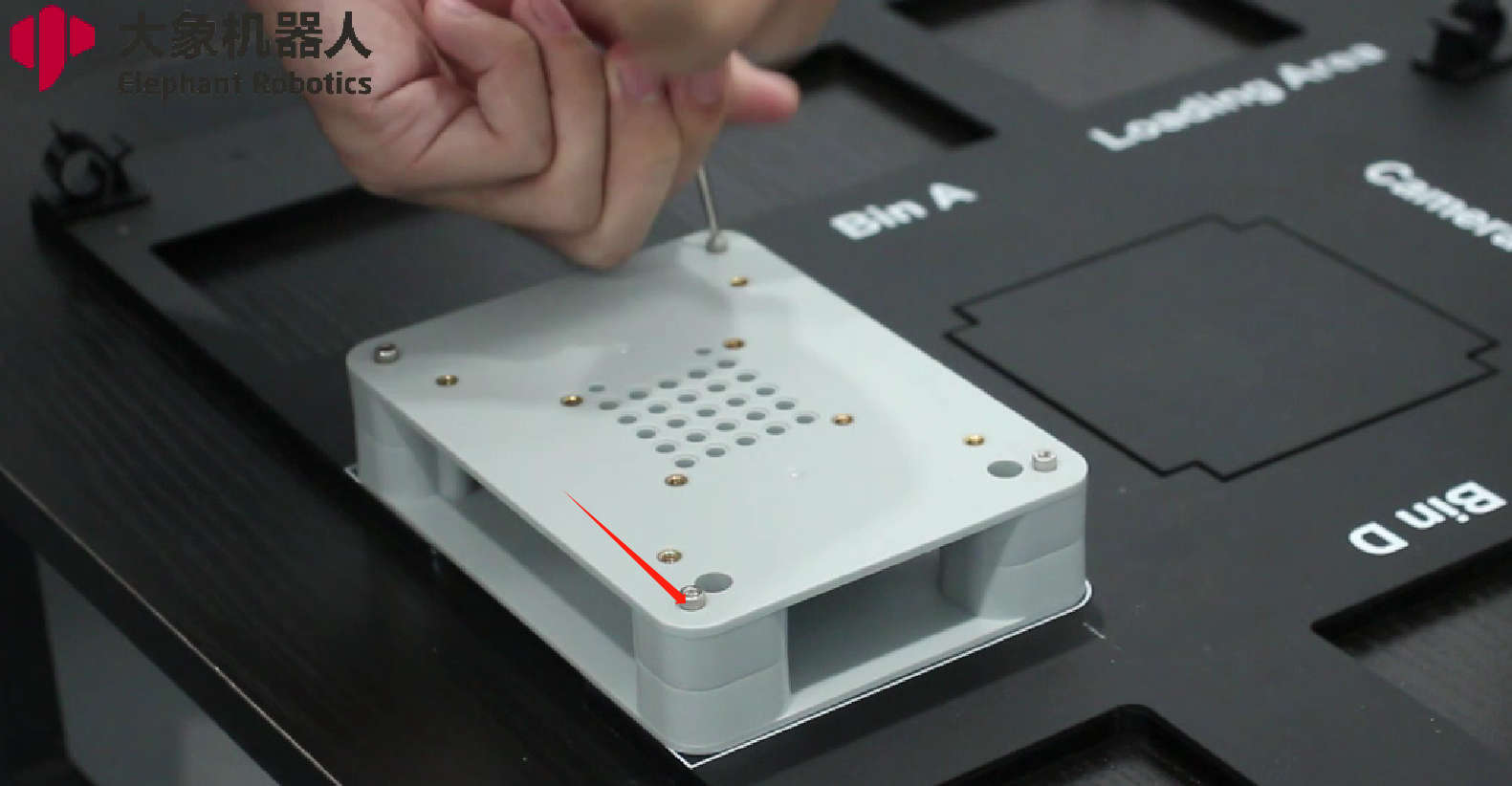
1 Install the base
1.1 Choose different base types for installation according to different models
- For the mechArm 270 M5 version robotic arm, start by using the M3x38 countersunk hex screws to install the base/stand.
- For the myCobot 280 M5 and myCobot 280 PI version robotic arm, start by using the M4x14 countersunk hex screws to install the base/stand.
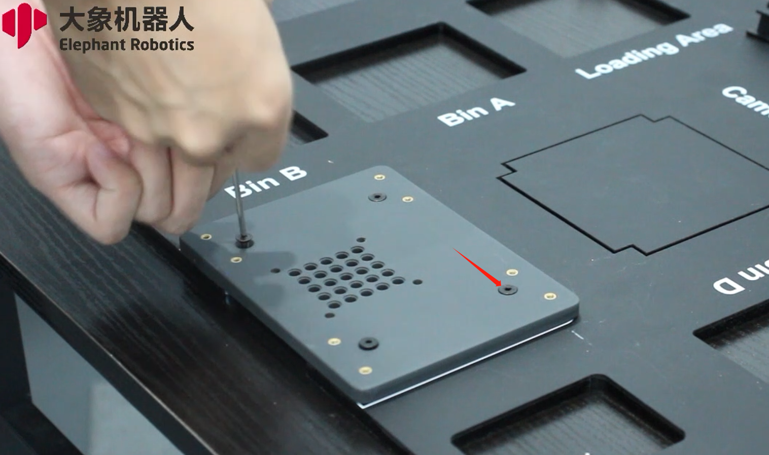
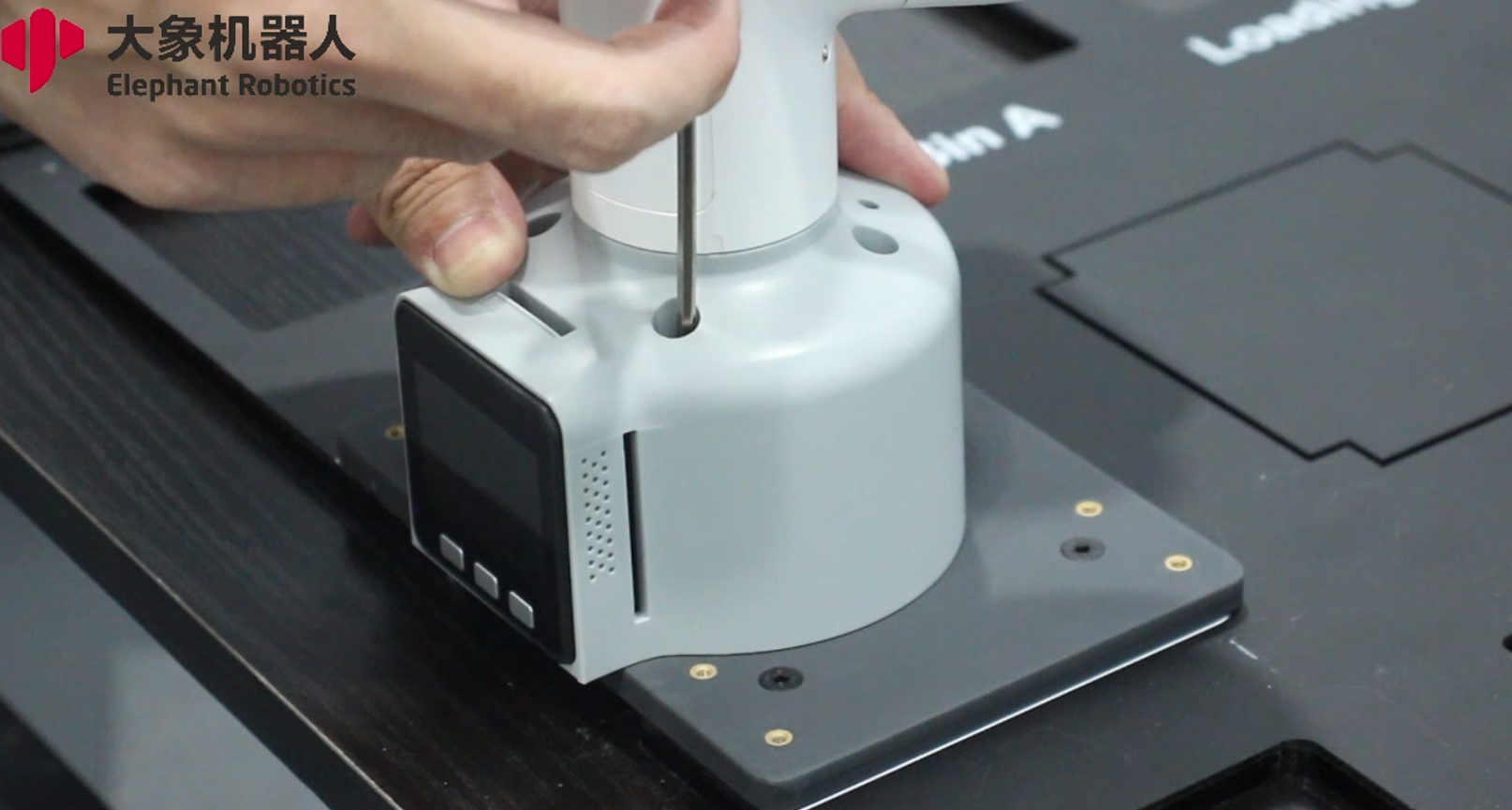
1.2 Taking the myCobot 280 M5 machine as an example, align the robotic arm with the holes and fix it with M4x35 screws.
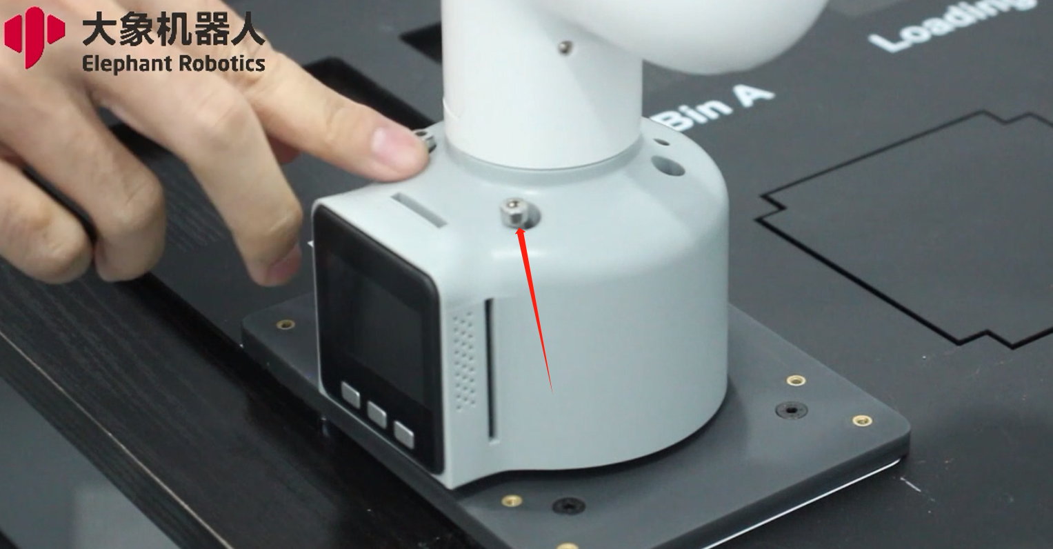
2 Install the camera bracket.
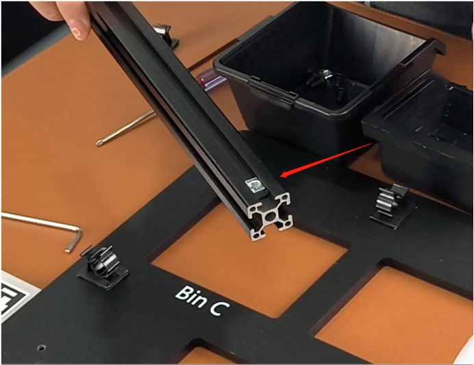
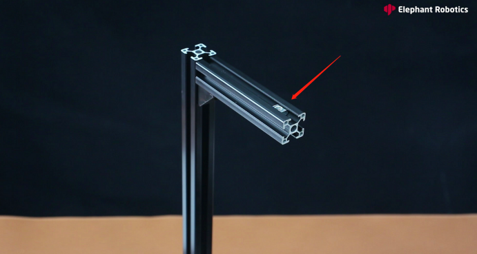
2.1 Place the T-nuts into the slots of the long profile, then use M5x8 pan head hex screws to install the corner brackets. Repeat this process for all three brackets.
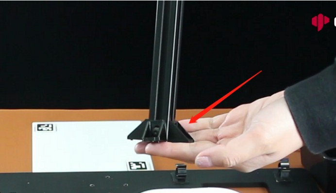
2.2 Repeat the process mentioned above to install the corner brackets on the short profiles.
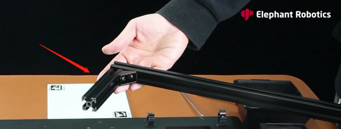
2.3 Place the T-nuts into the slots of the long profile, then use M5x8 pan head hex screws to attach the short profile onto the long profile.
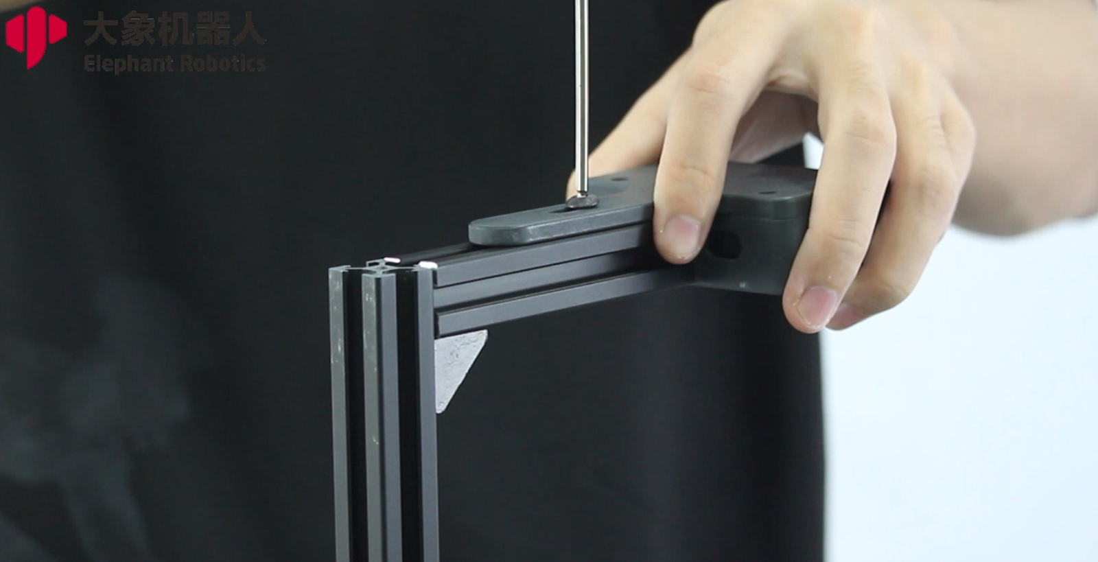
2.4 Align the assembled camera bracket with the holes on the acrylic plate. Use M5x10 pan head hex screws to secure it in place. Make sure to first loosely attach the three screws and then tighten them one by one, to avoid any misalignment of the holes.
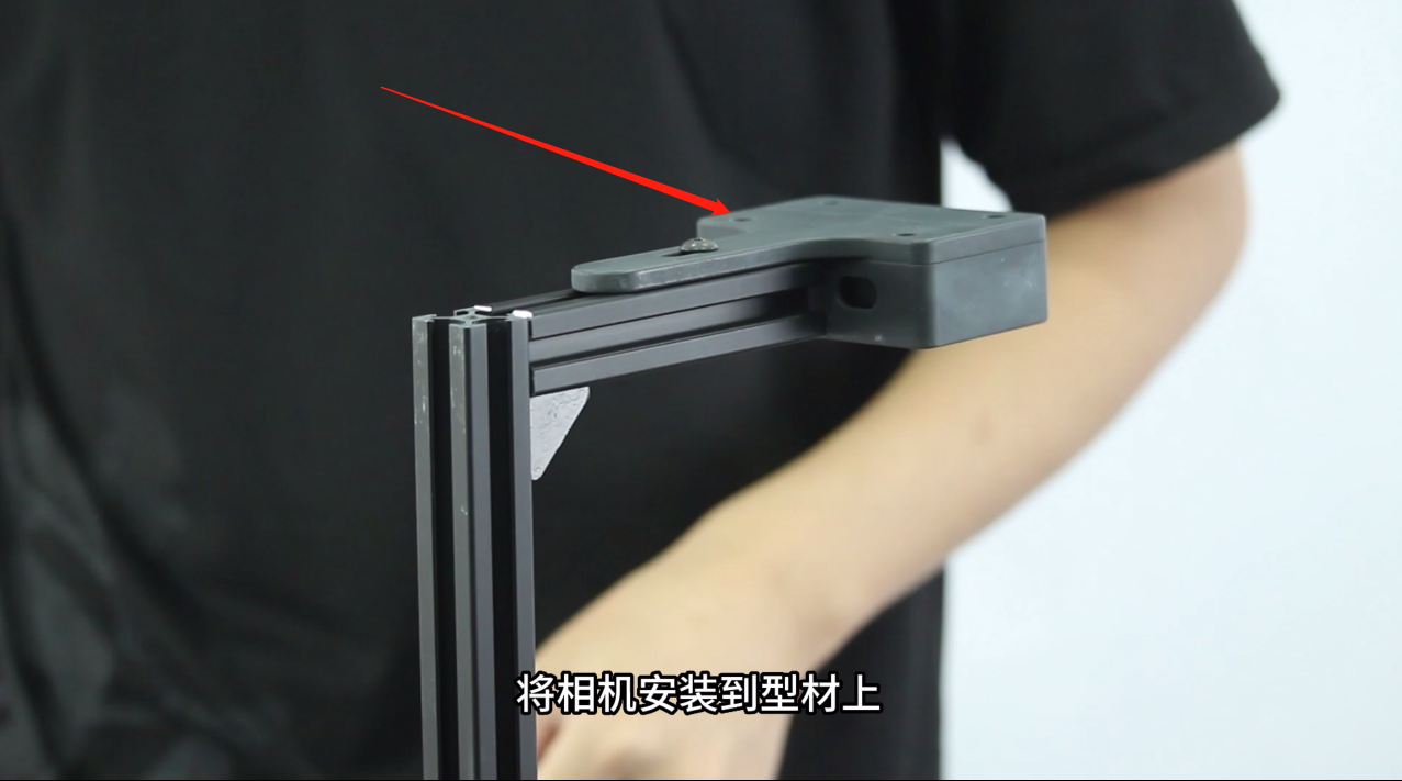
2.5 First, insert the T-nuts into the slots, then use M5x10 pan head hex screws to fasten the camera onto the bracket. Now, it's all installed and ready to use!
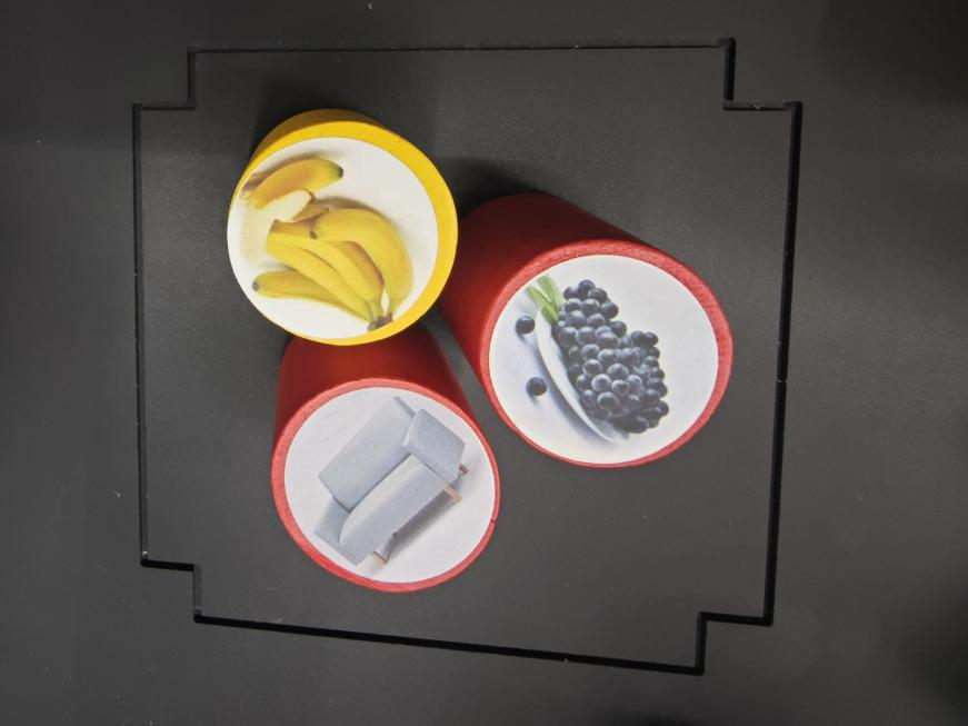
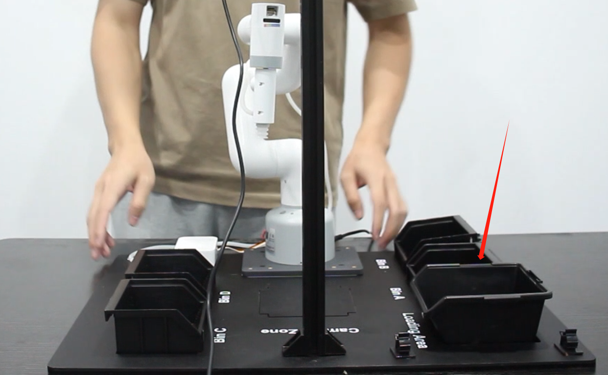
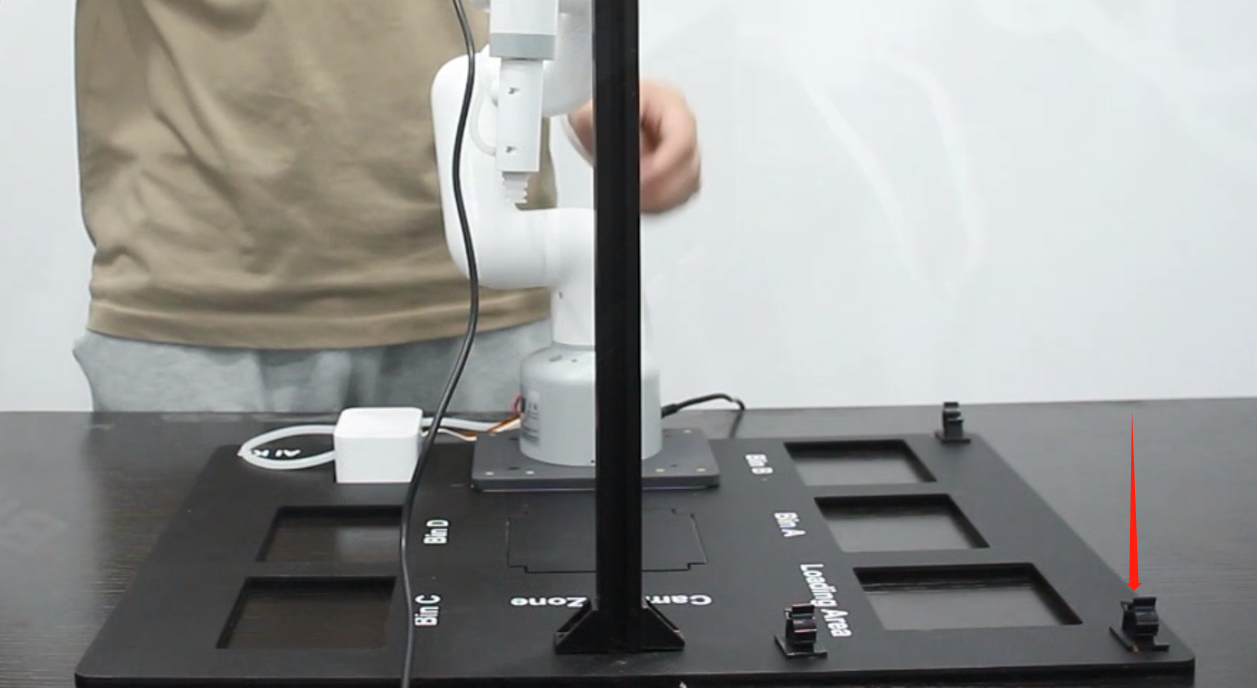
3 place parts
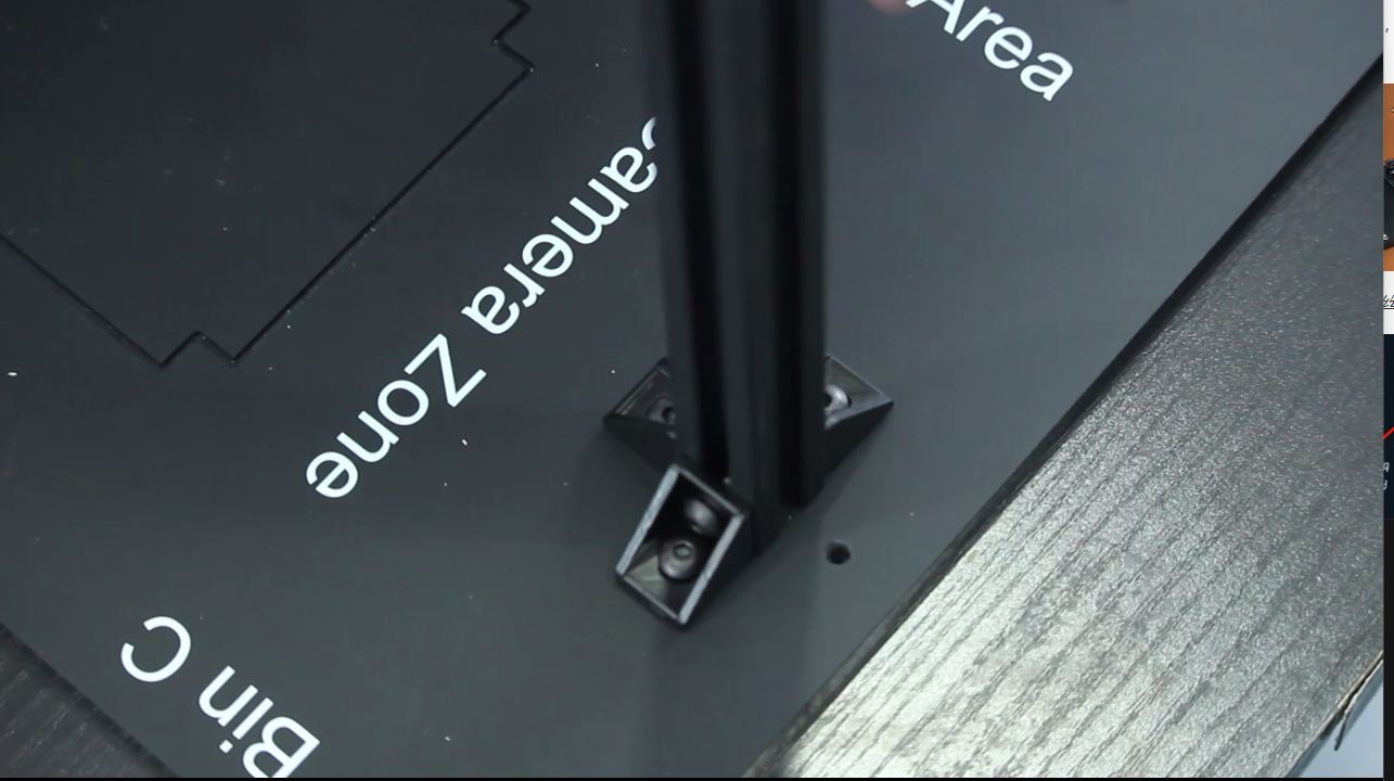
3.1 Arrange the small and large parts boxes.
4 Install the suction pump.
4.1 Insert the suction pump into the LEGO connector and install it at the end of the robotic arm.
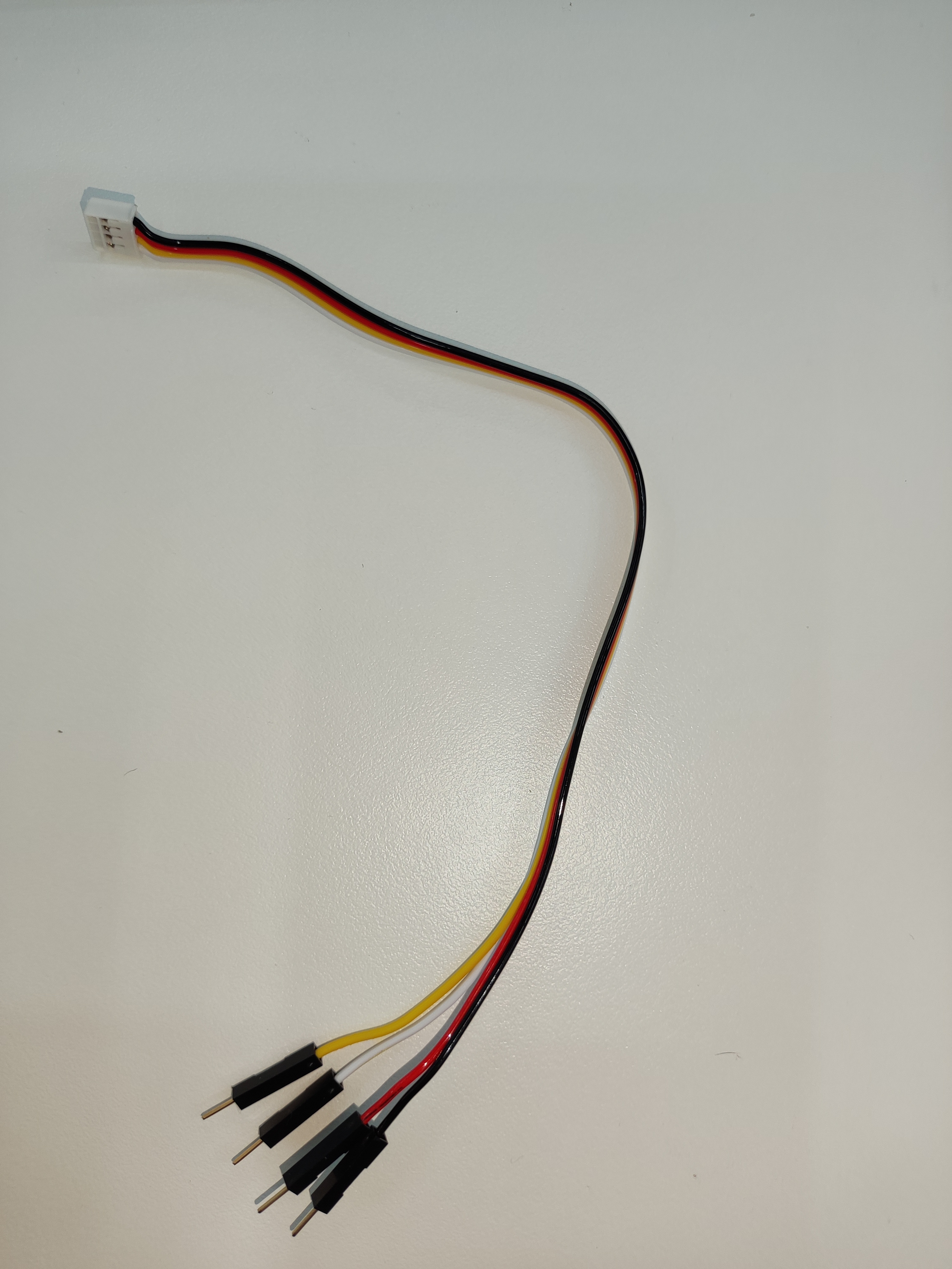
4.2 The Grove port is connected to the suction pump. According to the pin definition:
myCobot 280 M5、mechArm 270 M5 版本:
Select the male-female Dupont cable and insert the female end into the socket marked with pins on the suction pump box.
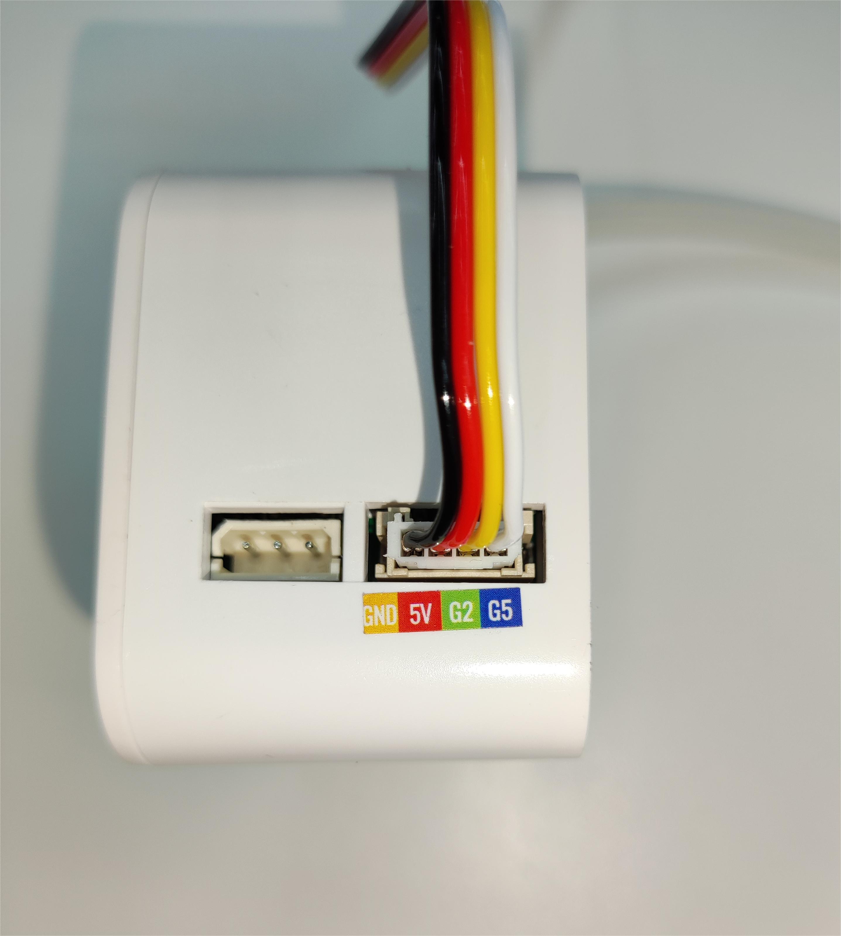
Then connect the wire to the base IO of the robot arm
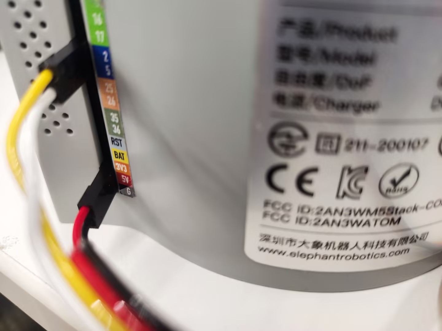
The left side is the suction pump pin, and the right side is the robot arm pin GND -> GND
5V -> 5V
G2 -> 2
G5 -> 5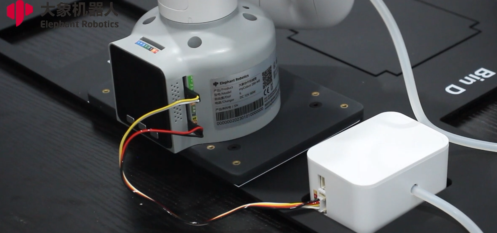
myCobot 280 PI Version:
Select the male-female Dupont cable and insert the female end into the socket marked with pins on the suction pump box.
Then connect the wire to the base IO of the robot arm
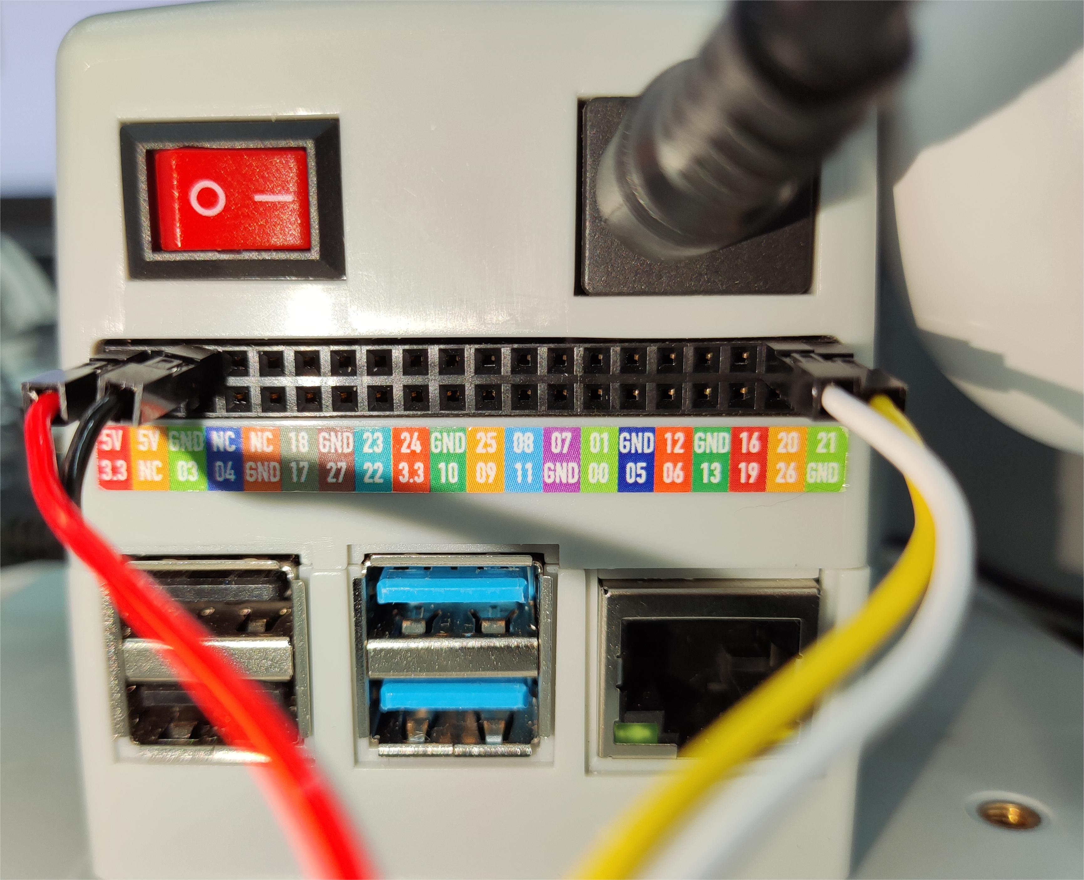
The left side is the suction pump pin, and the right side is the robot arm pin GND -> GND
5V -> 5V
G2 -> 21
G5 -> 20
5 Install the gripper
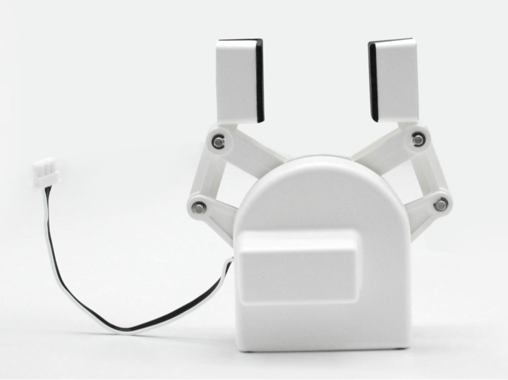
- Please check the specific connection myCobot adaptive gripper introduction to chapters.
6 Fixed routing
6.1 The self-adhesive cable clip is pasted on the acrylic base plate according to the position of the camera cable.
6.2 Use the black Velcro to secure the camera cord.
6.3 Put the wire into the wire clamp to secure.
6.4 Then use the white Velcro to fix the air tube of the suction pump, and the construction is completed.
7 Material Usage Instructions
Different end effectors use different materials.
- Color recognition-suction pump

- Shape recognition-suction pump:
3.yolov8 recognition-suction pump
- Depalletizing-suction pump
- Color recognition-gripper
6.yolov8 recognition-gripper