Robot Parameters
In the first chapter, we discussed the selling points of the product and its design concept, providing you with a panoramic perspective of the high-level understanding of the product. Now, let's move on to the second chapter - Robot Parameters. This chapter will be the key to your understanding of the product's technical details. A detailed understanding of these technical parameters will not only help you fully realize the advancement and practicality of our products, but also ensure that you can use these technologies more effectively to meet your specific needs.
1. Structural parameters
1.1 Robotic arm parameters
| Index | Parameters |
|---|---|
| Name | Little Elephant Collaborative Robotic Arm |
| Model | myCobot 280 RDK X5 |
| Degrees of freedom | 6 |
| Payload | 250g |
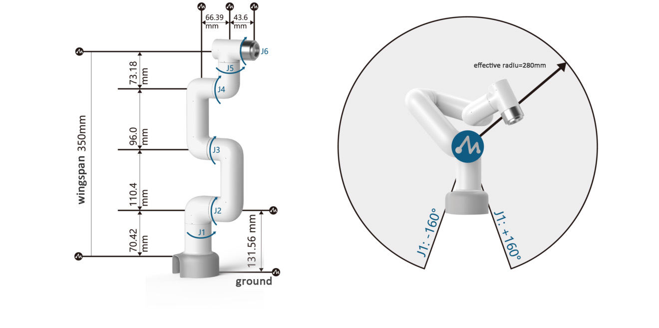
| Working radius | 280mm |
| Repeatability | ±0.5mm |
| Weight | 860g |
| Power input | 12V, 5A |
| Working temperature | -5-45℃ |
| Communication | Type-C |
1.2 Workspace
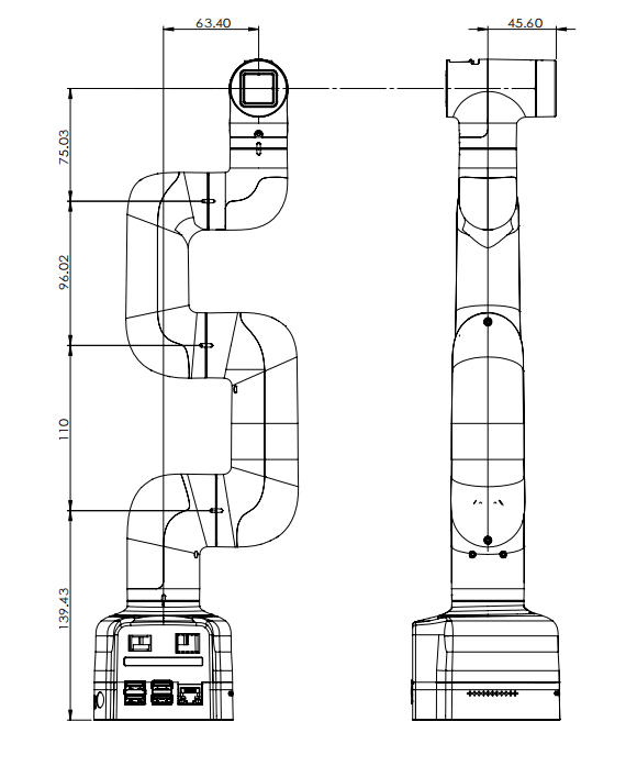
1.3 Specifications and dimensions
1.4 Joint range of motion
| Joint | Range |
|---|---|
| J1 | -168 ~ +168 |
| J2 | -135 ~ +135 |
| J3 | -150 ~ +150 |
| J4 | -145 ~ +145 |
| J5 | -165 ~ +165 |
| J6 | -180 ~ +180 |
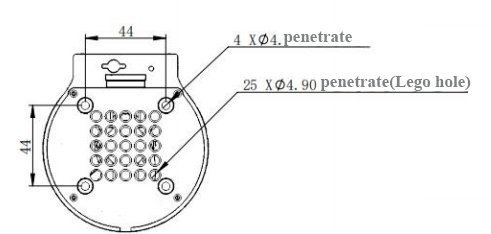
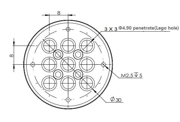
1.5 Hole installation
- The robot base is mounted with flanges. The base is compatible with both LEGO technology and M4 screw installation.
- The end of the robot is equipped with a flange, and the end of the robot arm is compatible with both Lego technology holes and screw threaded holes.
2.Electronic parameters
| Indicators | Parameters |
|---|---|
| CPU | 8x A55@1.5GHz |
| Bluetooth/wireless | Yes |
| USB | USB3.0 x2; USB2.0 x2 |
| Display screen | No |
| HDMI interface | microHDMI x2 |
| Custom buttons | No |
| IO interface | 40 |
3.Electrical characteristic parameters
3.1Electrical interface of the robotic arm base
Base introduction
- A. The left side of the base is shown below:
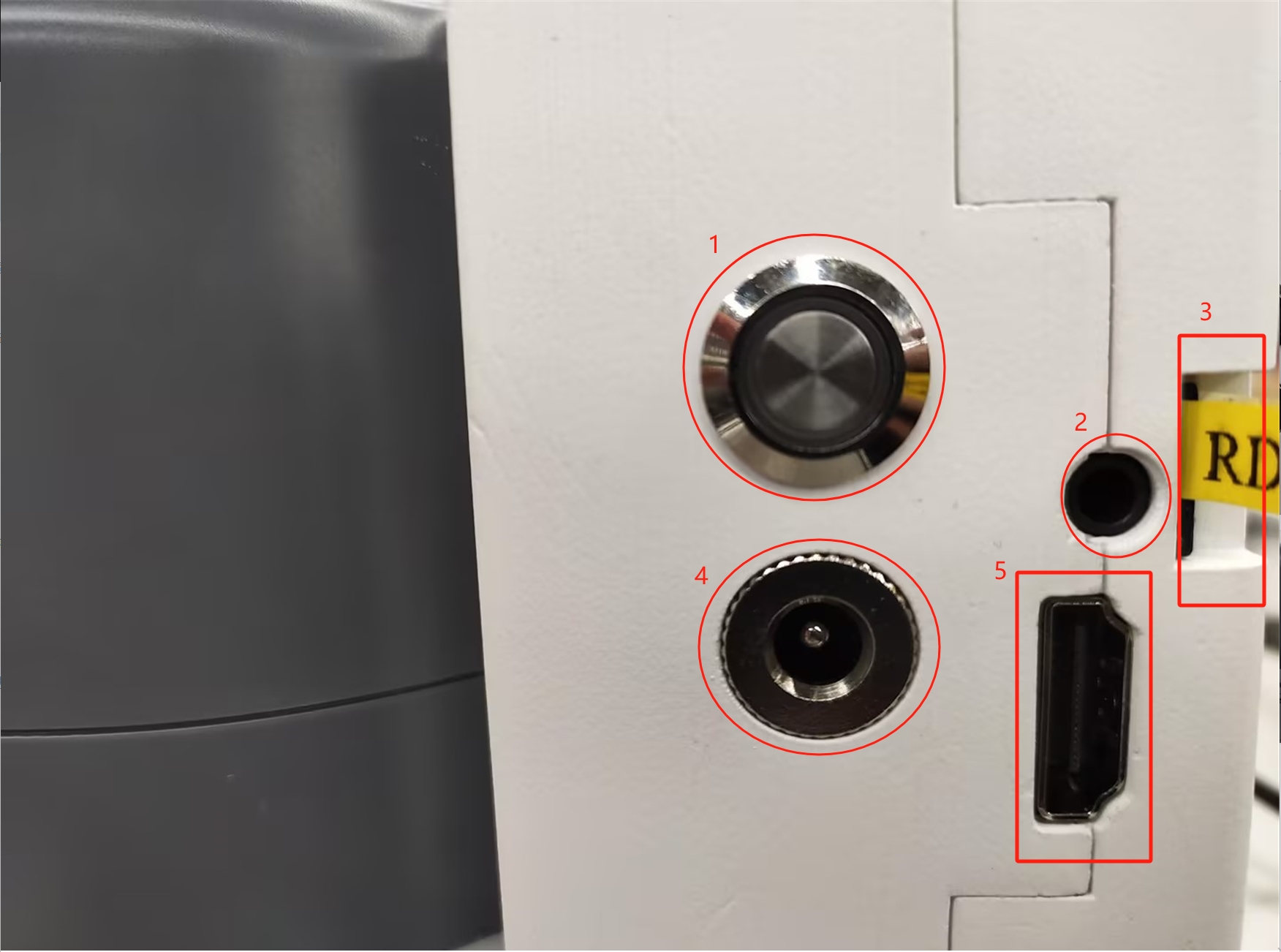
- ① Power button
- ② Headphone jack
- ③ SD card slot
- ④ DC12V power port
- ⑤ HDMI
B. The right side of the base is shown below:
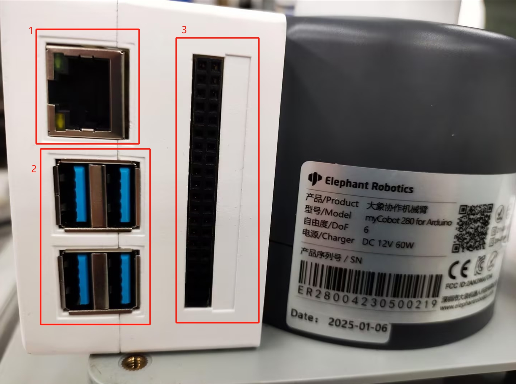
- ① Network port
- ② USB3.0 port
- ③ IO port
C. The top view of the base is shown below:
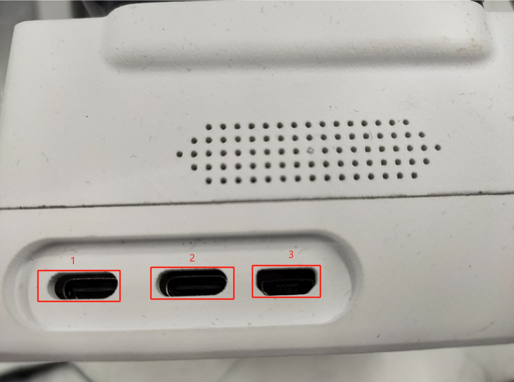
- ① Power supply Type-C interface
- ② Type-C interface
- ③ Micro USB interface
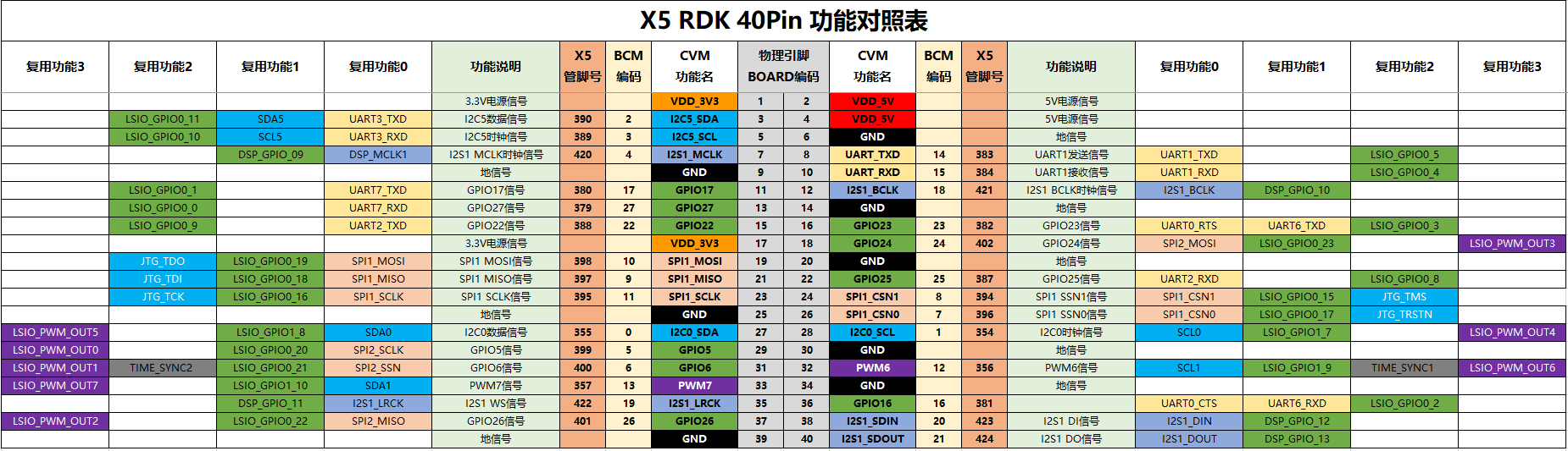
3.2 Bottom IO interface description
Note: The functional interface groups are all 2.54mm DuPont interfaces, and 2.54mm DuPont wires can be used externally.
The definitions of each interface are shown in the following table
4. Electrical interface of the end of the robotic arm
4.1 Introduction to the end of the robotic arm
A. The end of the robotic arm is shown in Figure 2.1.5.2-7 and Figure 2.1.5.2-8:
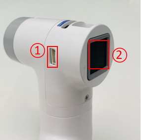
Figure 2.1.5.2-7 End of the robotic arm
- ① Servo interface
- ② Atom
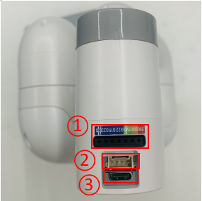
Figure 2.1.5.2-8 End of the robot arm
- ① Functional interface group 2
- ② Grove
- ③ Type C
4.2 Terminal interface description
- A. The definitions of each interface of functional interface group 2 are shown in the following table:
| Label | Signal name | Type | Function | Remarks |
|---|---|---|---|---|
| 5V | 5V | P | DC 5V | |
| GND | GND | P | GND | |
| 3V3 | 3V3 | P | DC 3.3V | |
| G22 | G22 | I/O | GPIO22 | |
| G19 | G19 | I/O | GPIO19 | |
| G23 | G23 | I/O | GPIO23 | |
| G33 | G33 | I/O | GPIO33 |
Note:
I: Input only.
I/O: This function signal includes input and output combination.
When the tube corner is set as output, it will output voltage 3.3V.
The source current of a single tube corner decreases with the increase of the number of pins, from about 40mA to 29mA.
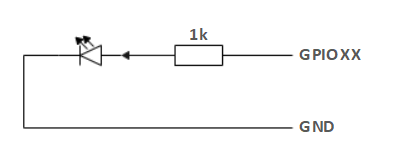
If a GPIO is set to output mode, it outputs a high level signal, the circuit connection is shown in Figure 2.1.5.2-9, and the LED light will light up.
Figure 2.1.5.2-9
B. Type C interface: can be used to connect to the PC for communication and update firmware.
C. Grove: defined as shown in Figure 2.1.5.2-10
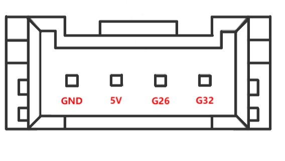
Figure 2.1.5.2-10 Grove
D. Servo interface: used for the end extension gripper, currently supports the matching adaptive gripper.
E. Atom: used for 5X5 RGB LED (G27) display and button function (G39)
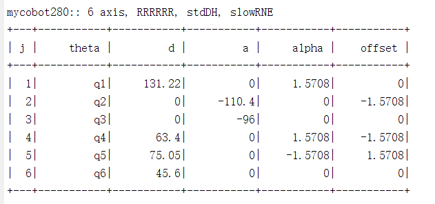
5. Cartesian coordinate parameters
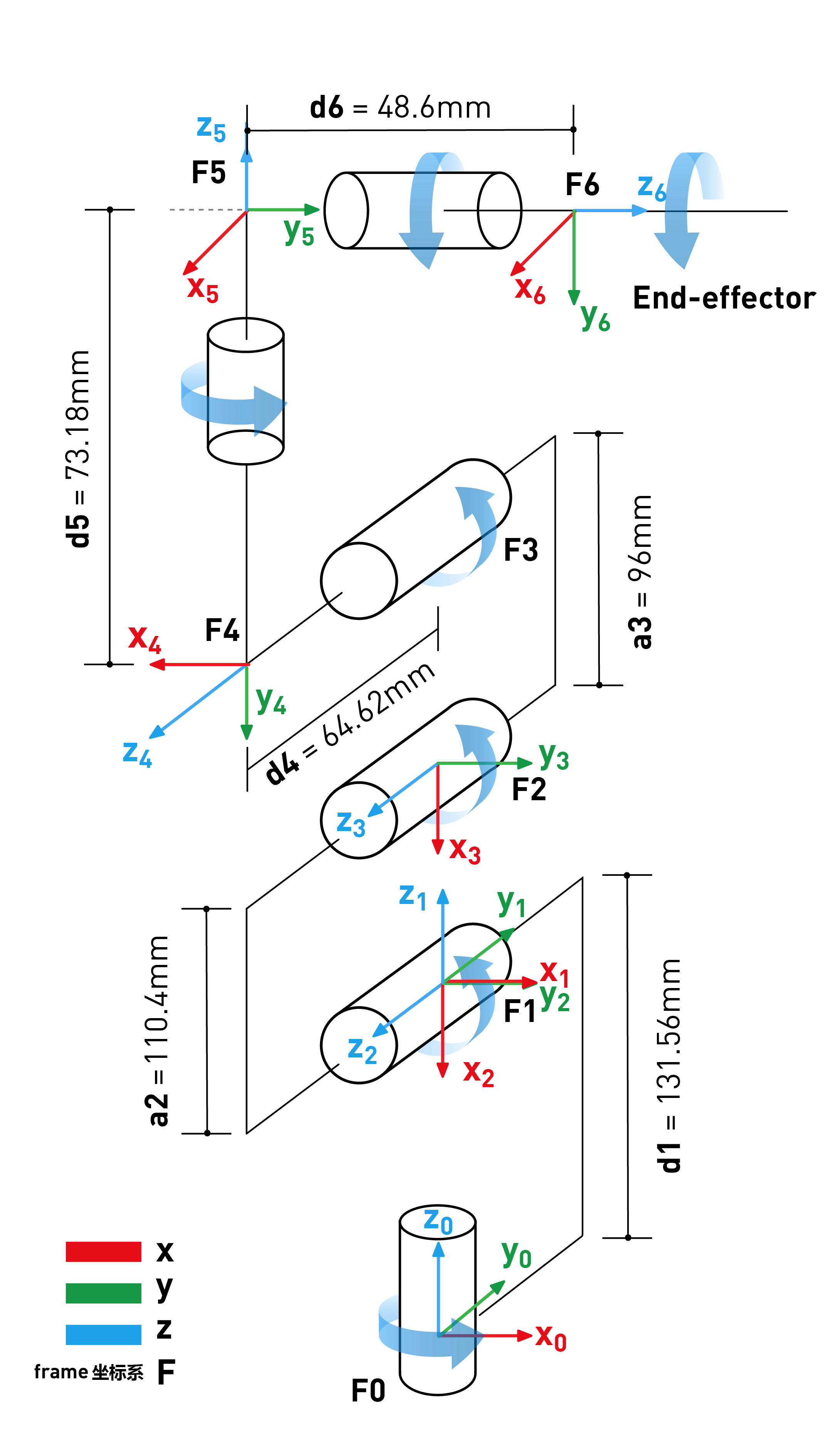
The SDH parameters are shown in the figure below