myGripper F100 Force Control Gripper
1 Product Display

2 Product Introduction
myCobot Pro Force Control Gripper is a high-performance robot end effector designed for multi-functional grasping needs. Made of PC and PBT materials and manufactured by precision injection molding, it ensures the firmness and durability of the product. The gripping range of the gripper is 0-100 mm (default fingertip), and it supports multi-speed torque adjustment to meet the grasping needs of different forces. The rated load is 500 grams, and the repeatability accuracy is 0.5 mm, which can adapt to various robot grasping operation scenarios.
3 Compatible models
ER myCobot 320 series
ER Mercury A/B/X series
ER myCobot Pro 630
ER myCobot Pro 600
Other general robots
4 Applicable scenarios
Experimental operation: In scientific research experiments, complete the grasping and moving of test tubes, utensils, etc. to ensure the safety and accuracy of the experiment.
Educational demonstration: As a teaching tool, it helps students understand the principle of robot grasping and cultivate practical ability.
Material handling: In simulated production lines or warehouses, materials of various specifications are handled to improve work efficiency.
5 Specifications
Product Specifications
| Name | myGripper F100 Force Control Gripper |
|---|---|
| Material | PC, PBT |
| Dimensions | 156X106X61mm |
| Process Technology | Injection Molding |
| Gripping Range | 0-100 mm (default fingertip) |
| Repeatability Accuracy | 0.5 mm |
| Service Life | 300,000 Opening and Closing Times |
| Drive Mode | Electric Drive |
| Transmission Mode | Gear + Connecting Rod |
| Weight | 340 g |
| Rated Load | 500g |
| Operating Voltage | 24V |
| Fixing Method | Screw Fixing |
| Environment Requirements | Normal Temperature and Pressure |
| Control Interface | RS485/IO Control/button control |
| Cable interface model | M8-8PIN |
Pin sequence description
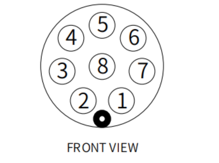
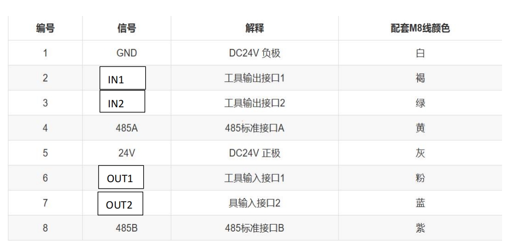
Numbers 1 and 5 connect GND and 24V, numbers 2 and 3 are for controlling IO input, numbers 6 and 7 are for IO output, and numbers 4 and 8 are for 485 communication, which is for receiving and sending instructions with the gripper
Notes: Please distinguish the line sequence according to the line mark. If the line mark is lost, detached, or forgotten, please contact our staff to cooperate in determining the line sequence. If you do not contact our staff, the gripper will be damaged due to the wrong line sequence, and the consequences will be at your own risk
5.1 Working principle
Driven by the motor, the surface of the manipulator's fingers moves back and forth in a straight line to achieve the opening or closing action. By setting the clamping torque, the impact of the workpiece is minimized, the positioning point is controllable, and the clamping is controllable.
5.2 Assembly steps
Take mycobot320 as an example, other models can refer to this step for installation
Use screws and gaskets to install the clamp connector to the end flange of the robot arm

Then use screws to install the clamp on the connector


Finally, use M8 aviation wire to connect the clamp and the robot arm

5.3 Control method
- Support python, ros, serial port control
- pthon: Please jump to the Elephant Robot host product accessories use section and check python control method
- Screen IO button control
- Serial port control
- ros control
Screen control
The myCobot Pro force-controlled gripper has a screen display function, and there are buttons under the screen for easy control of the screen. By selecting the interface, you can more conveniently control the gripper and understand the gripper information. Screen information and Overall function description
| Interface | Function |
|---|---|
| Main interface | View the gripper information, such as: Position Set speed Current Input IO Output IO |
| Setting interface | View and set the gripper data |
| Set baud rate interface (Modbus Config) | View and change the device baud rate |
| IO enable interface (IO Config) | View and enable IO, the default IO is enabled |
| Gripper control interface (Manual Config) | Open-control the gripper to open Close-control the gripper to close Release-disable the gripper (the gripper will not have torque at this time, and the gripper can swing freely) Hold - enable the gripper (enable the gripper, and the gripper has torque at this time) |
| Version information interface (Information) | Firmware - Firmware version number Servomotor - Gripper version number and gripper ID |
Main interface
Entering the gripper main interface, we can see some real-time information of the gripper on the screen, which makes it easier to know the gripper information. The main interface mainly has the following information as shown in the figure
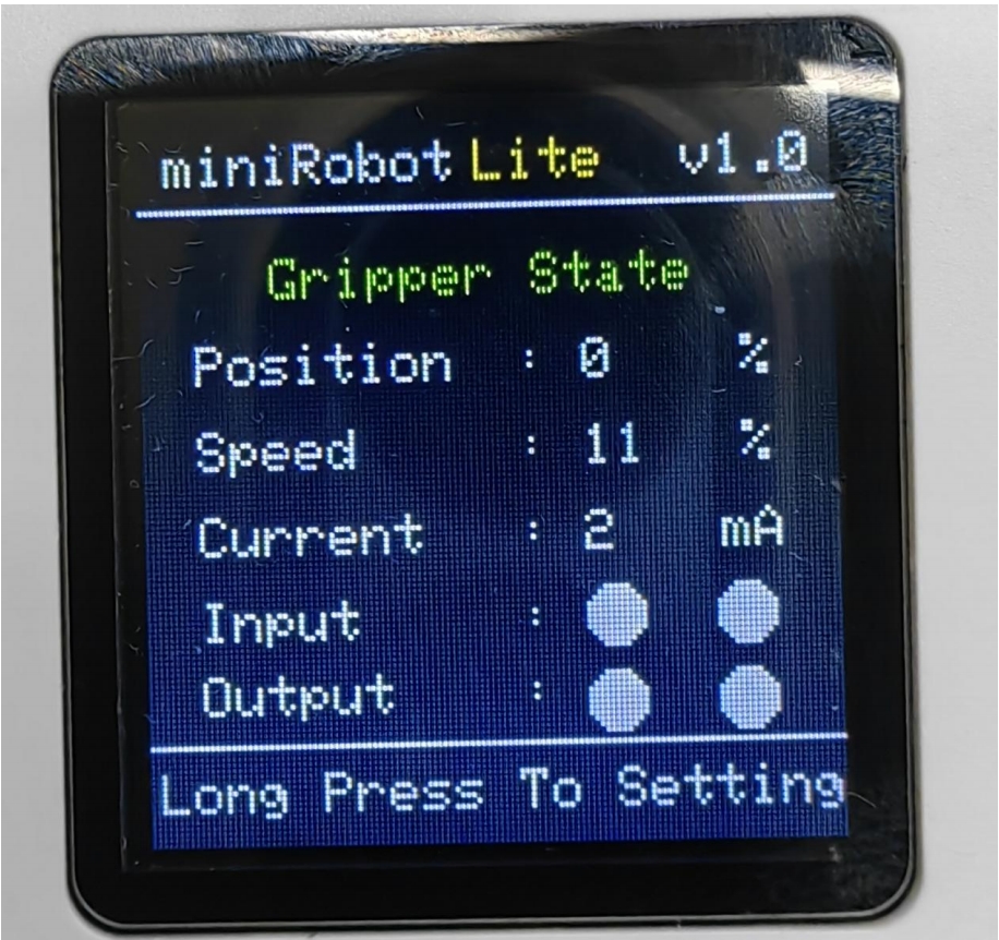
The main interface displays the gripper angle, speed, current, input and output IO level in real time
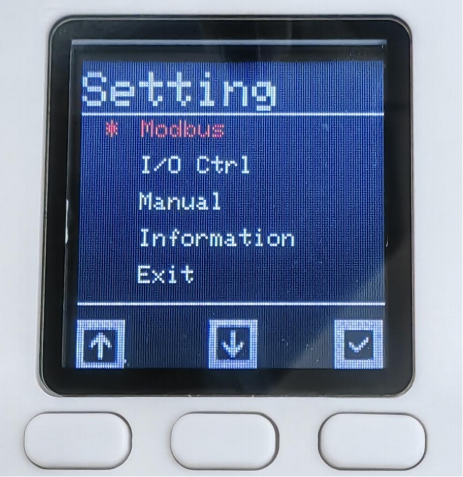
Setting interface
Press and hold the confirmation button for 2s in the main interface to enter the main interface
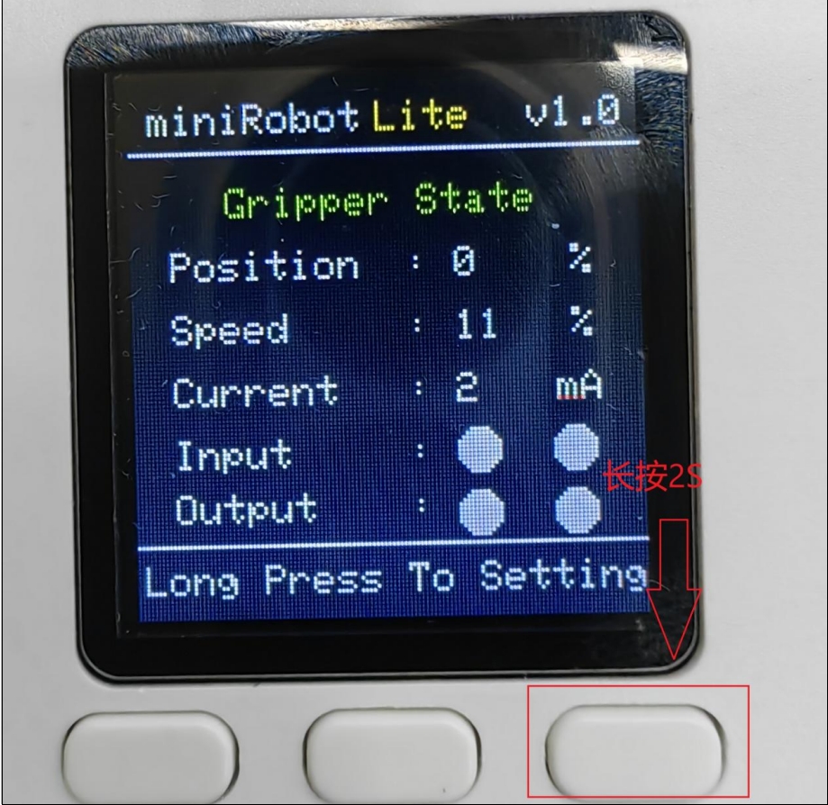
Setting interface, you can move up and down and select by pressing the button
Baud rate setting
Click Modbus in the setting interface to enter the Modbud Config interface. Click Baudrate to enter the interface, select the baud rate you want to set and click Confirm. When the color of the origin next to the baud rate changes, it proves that the setting is successful
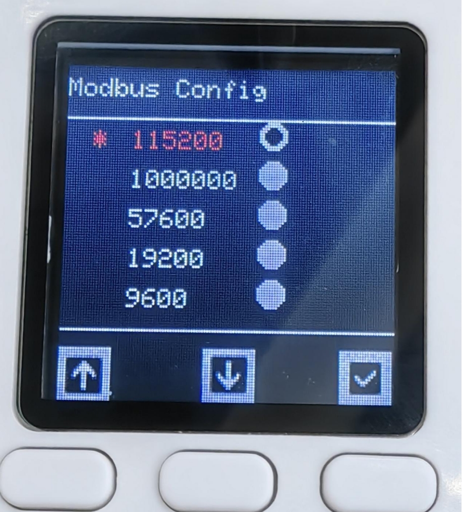
After setting, find Exit and click to exit the current interface
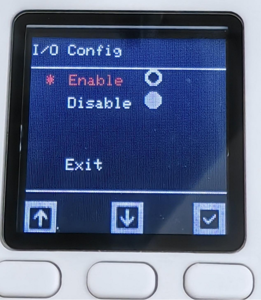
IO enable setting
Setting interface selection I/O Ctrl, enter the I/O Config interface, by default, IO is enabled, if not, use IO control, you can select Disable to turn off IO control
Manual interface
Select Manual in the setting interface to enter the Manual Control interface to quickly and conveniently control the gripper
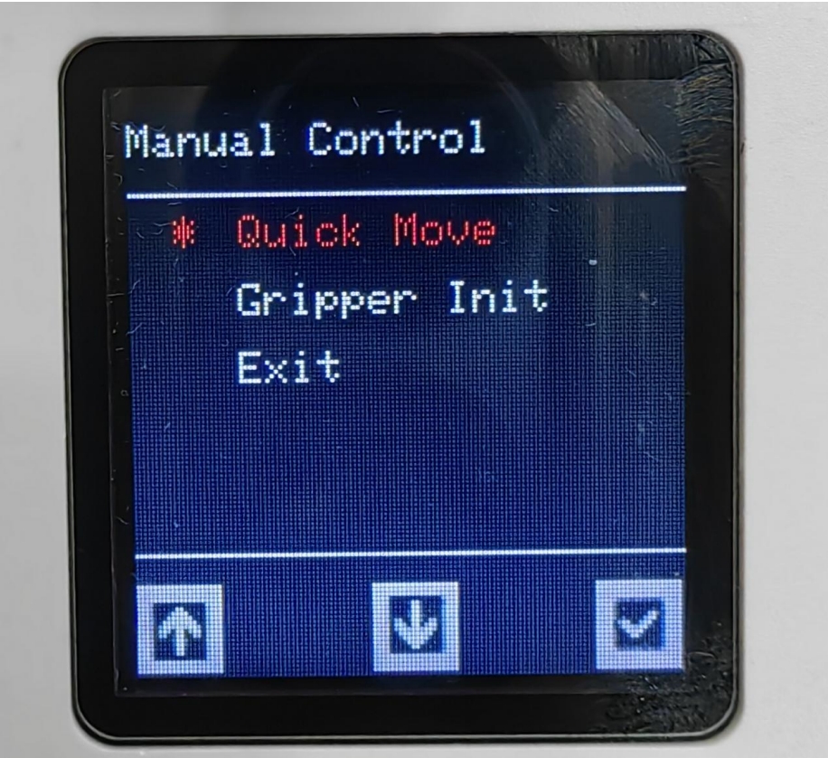
Select Quick Move to enter the gripper control interface, as shown in Figure 4.7, select Gripper Init to enter the gripper configuration interface
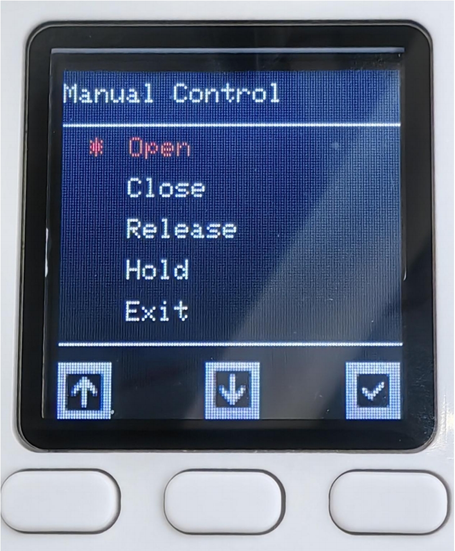
Open-set the gripper to open, Close-set the gripper to close, Pelease-set the gripper to disable, Hold-set the gripper to enable, Exit-exit the current interface
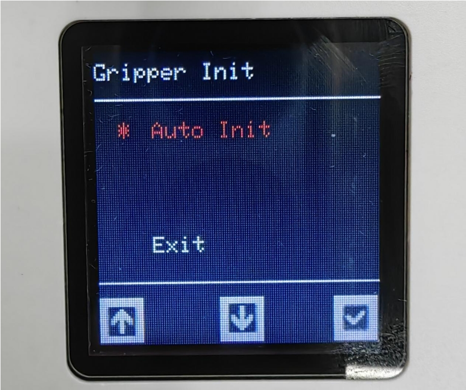
Select Auto Init to set the gripper zero position
Information interface
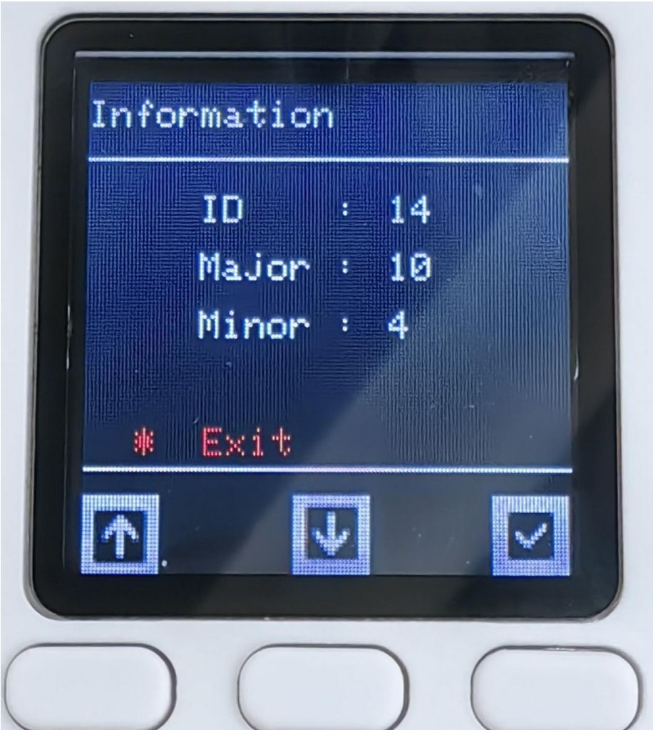
By selecting Information to enter the interface, we can see two options: Firmware and Servomotor. The former is the firmware version number. Click it to view the current firmware major and minor version numbers. The latter is to view the click information. Click it to see the ID and the main and minor versions of the motor.
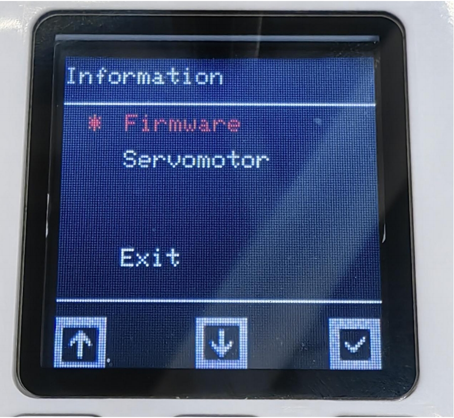
Click Firmware to view the firmware version and the ID in the device ID command.
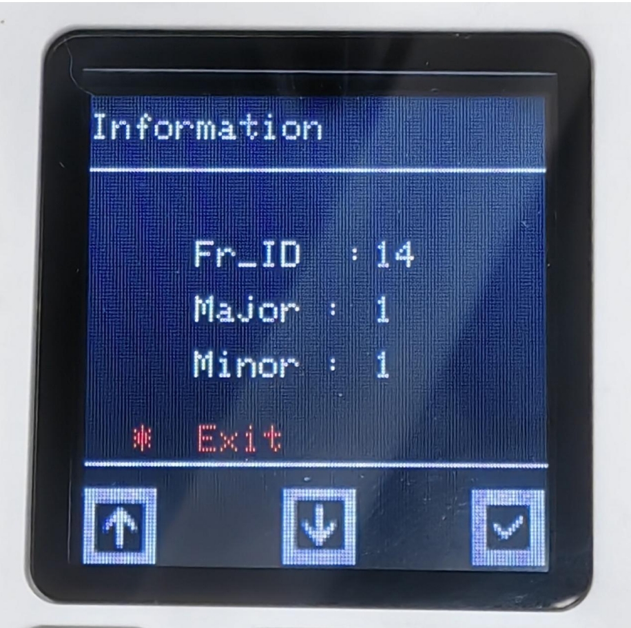
Click Servomotor to view the motor version and ID. The ID cannot be modified.
IO control
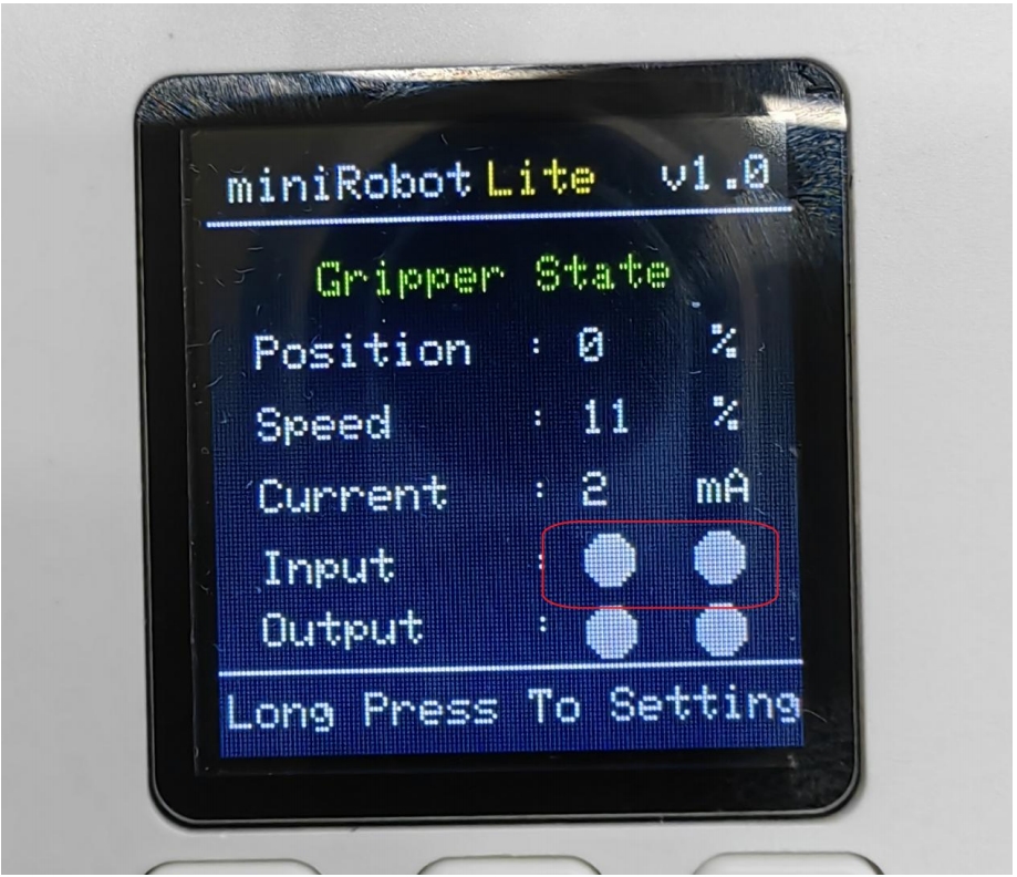
According to the above pin sequence description, find the line corresponding to OUT1 OUT2, input 24V, and when a high and a low level are input, the gripper will move. On the contrary, when a high and a low level are given, the gripper will move in the opposite direction. The IO input status can be observed on the main screen interface. When there is no IO input, it will be white, and when there is IO input, a black dot will appear.
Serial port control method
USB-485 module wiring:
Connect the 24V, GND, 485_A (T/R+, 485+), 485_B (T/R-, 485-) of the gripper end, a total of 4 wires, the power supply is a 24V DC regulated power supply, and insert the USB port of the module into the USB port of the computer
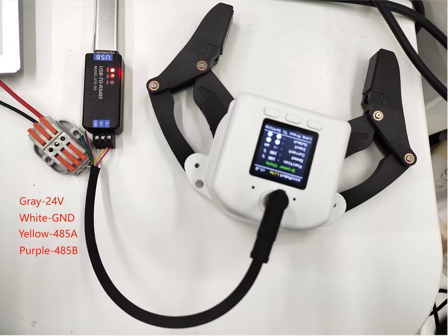
485A connected to 485 to USB module A+;
485B connected to 485 to USB module B-;
24V connected 24V DC regulated power supply positive pole;
GND connected to 24V DC regulated power supply negative pole
Serial port debugging assistant debugging:
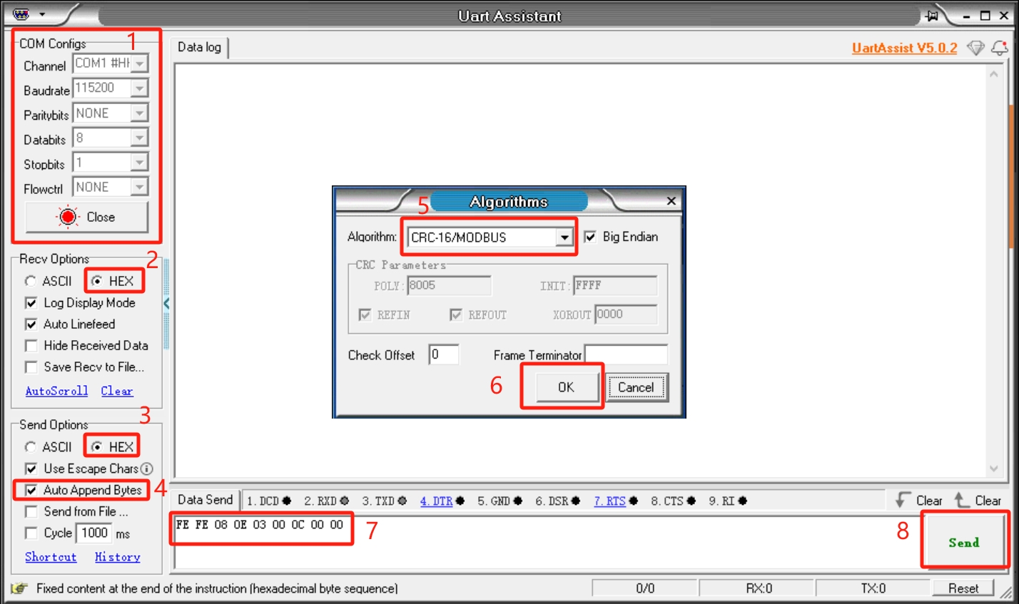
Users can use UartAssist serial port debugging assistant, refer to the figure below to send the corresponding gripper command, CRC checksum does not need to be filled in, UartAssist serial port debugging assistant will automatically generate it.
Default configuration of the gripper serial port
- Gripper ID: 14
- Baud rate: 115200
- Data bit: 8
- Stop bit: 1
- Check bit: No check bit
Protocol usage instructions
The gripper uses a custom protocol. An instruction consists of a frame header (2byte), length (1byte), address code ID (1byte), Function code (1byte), register address (2byte), register data (2byte), check code (2byte) Let's take reading the gripper angle as an example
| Frame header | Length | ID | Function code | Register address | Register data/parameter | CRC-16MODBUS check code |
|---|---|---|---|---|---|---|
| Fe Fe | 08 | 0e | 03 | 00 0C | 00 00 | B1 C0 |
Frame header: 254 254
Length: Command length 08
ID: 0E, can be modified in the device, the default ID is 14, 0E represents the current ID of the gripper is 14
Function code: Identify whether the instruction is a setting or acquisition function, 06 (write operation to the register)/03 (read operation to the register).
Register address: 00 0c Gripper function corresponding register address
Register parameter: 00 00, no parameter is required in the read instruction, 00 00 can be given, and data is written to the gripper address for the parameter in the setting instruction.
CRC check: B1 C0, to ensure that the terminal device does not respond to data that has changed during the transmission process,
to ensure the security and efficiency of the system. CRC check adopts the 16-bit cyclic remainder method. Verify the frame header, length, function code, register address, and register parameters in hexadecimal format to get the B1 C0 check code.
Command Overview
Read the firmware major version number
Command: fe fe 08 0e 03 00 01 00 00 72 51
Function code: 03 Read operation
Parameter: None
Return: fe fe 08 0e 03 00 01 00 01 B2 90
Note: Data return 00 01, return version number is 1
Read the firmware minor version number
Command: FE FE 08 0E 03 00 02 00 00 72 A1
Function code: 03 Read operation
Parameter: None
Return: FE FE 08 0E 03 00 02 00 01 B2 60
Note: Data return 00 01, indicating that the return version number is 1
Set/read device ID number
Set
Command: FE FE 08 0E 06 00 03 00 0E 76 BD
Function code: 06 write operation
Parameter: 00 0E, ID setting range (1-254)
Return: FE FE 08 0E 06 00 03 00 01 72 FD
Note: Success returns 00 01, failure returns 00 00, after the device ID is modified, the ID in the instruction also needs to be modified to be the same to communicate
Read
Instruction: FE FE 08 0E 03 00 04 00 00 73 41
Function code: 03 read operation
Parameter: None
Return: FE FE 08 0E 03 00 04 00 0E B7 C0
Note: Data return 00 0E, indicating the current gripper ID number
Set/read 485 baud rate
Set
Instruction: FE FE 08 0E 06 00 05 00 00 73 1D
Function code: 06 write operation
Parameter: parameter 00 00, 0-115200, 1-1000000, 2-57600, 3-19200, 4-9600, 5-4800, If set to 1000000, the parameter is changed to 00 01
Return: FE FE 08 0E 06 00 05 00 01 72 FD
Note: Success returns 00 01, failure returns 00 00
Read
Command: FE FE 08 0E 03 00 06 00 00 B3 E0
Function code: 03 read operation
Parameter: None
Return: FE FE 08 0E 03 00 06 00 00 B3 E0
Note: Return data 00 00, the baud rate value corresponding to the setting parameter
Set the gripper enable state
Command: FE FE 08 0E 06 00 0A 00 00 B0 EC
Function code: 06 write operation
Parameter: 00 00, 00 means disconnect enable, 00 01 means enable
Return: FE FE 08 0E 06 00 0A 00 01 70 2D
Note: Success returns 00 01, failure returns 00 00
Set/read the gripper angle
Set
Command: FE FE 08 0E 06 00 0B 00 64 9B BC
Function code: 06 write operation
Parameter: Parameter 00 64, set the angle to fully open
Return: FE FE 08 0E 06 00 0B 00 01 B0 7C
Mark: Success returns 00 01, failure returns 00 00
Read
Command: FE FE 08 0E 03 00 0C 00 00 B1 C0
Function code: 03 Read operation
Parameter: None
Return: FE FE 08 0E 03 00 0C 00 64 5A C1
Mark: Return data 00 64, indicating that the current angle is 100, fully open state
Set the gripper zero position
Command: FE FE 08 0E 06 00 0D 00 00 71 5D
Function code: 06 Write operation
Parameter: None
Return: FE FE 08 0E 06 00 0D 00 01 B1 9C
Mark: Success returns 00 01, failure returns 00 00
Note: When setting the zero position, the gripper will move by itself. If there is an object blocking the movement, the setting will fail. Please check whether there are any obstacles around the gripper before setting.
Read the gripper clamping status
Command: FE FE 08 0E 03 00 0E 00 00 71 61
Function code: 03 Read operation
Parameter: None
Return: FE FE 08 0E 03 00 0E 00 01 B1 A0 Mark: 00 01, return data 0 is moving, 1 is stopped and no clamping is detected, 2 is stopped and clamping is detected, 3 is detected and the object falls
Set/read the gripper P value
Set
Command: FE FE 08 0E 06 00 0F 00 64 5A FD
Function code: 06 Write operation
Parameter: Parameter 00 64, set the P value 100, setting range (1-150)
Return: FE FE 08 0E 06 00 0F 00 01 71 3D
Note: Success returns 00 01, failure returns 00 00
Read
Command: FE FE 08 0E 03 00 10 00 00 77 01
Function code: 03 Read operation
Parameter: None
Return: FE FE 08 0E 03 00 10 00 64 9C 00
Note: Return data 00 64, indicating that the current P value is 100
Set/read the gripper D value
Set
Command: FE FE 08 0E 06 00 11 00 64 5C 9D
Function code: 06 Write operation
Parameter: Parameter 00 64, set the D value 100, setting range (1-150)
Return: FE FE 08 0E 06 00 11 00 01 77 5D
Note: Success returns 00 01, failure returns 00 00
If the gripper shakes, the D value can be appropriately increased
Read
Command: FE FE 08 0E 03 00 12 00 00 B7 A0
Function code: 03 Read operation
Parameter: None
Return: FE FE 08 0E 03 00 12 00 64 5C A1
Note: Return data 00 64, indicating that the current D value is 100
Set/read gripper I value
Set
Command: FE FE 08 0E 06 00 13 00 00 77 3D
Function code: 06 Write operation
Parameter: Parameter 00 00, set I value to 0, setting range (1-150)
Return: FE FE 08 0E 06 00 13 00 01 B7 FC
Note: Success returns 00 01, failure returns 00 00
Read Command: FE FE 08 0E 03 00 14 00 00 B6 40
Function code: 03 Read operation
Parameter: None
Return: FE FE 08 0E 03 00 14 00 00 B6 40
Note: Return data 00 00, indicating that the current I value is 0
Set/read the clockwise runnable error of the gripper
Set
Command: FE FE 08 0E 06 00 15 00 01 B6 1C
Function code: 06 Write operation
Parameter: Parameter 00 01, setting value is 1, setting range (0-16)
Return: FE FE 08 0E 06 00 15 00 01 B6 1C
Note: Success returns 00 01, failure returns 00 00
Read
Command: FE FE 08 0E 03 00 16 00 00 76 E1
Function code: 03 Read operation
Parameter: None
Return: FE FE 08 0E 03 00 16 00 01 B6 20
Note: Return data 00 01, indicating that the current value is 1
Set/read the clockwise runnable error of the gripper
Set
Command: FE FE 08 0E 06 00 17 00 01 76 BD
Function code: 06 Write operation
Parameter: Parameter 00 01, setting value is 1, setting range (0-16)
Return: FE FE 08 0E 06 00 17 00 01 76 BD
Note: Success returns 00 01, failure returns 00 00
Read
Command: FE FE 08 0E 03 00 18 00 00 B5 80
Function code: 03 Read operation
Parameter: None
Return: FE FE 08 0E 03 00 18 00 01 75 41
Note: Return data 00 01, indicating that the current value is 1
Set/read the minimum starting force of the gripper
Set
Command: FE FE 08 0E 06 00 19 00 18 7F 1D
Function code: 06 Write operation
Parameter: 00 18
Return: FE FE 08 0E 06 00 19 00 01 B5 DC
Note: Success returns 00 01, failure returns 00 00
Read
Command: FE FE 08 0E 03 00 1A 00 00 75 21
Function code: 03 Read operation
Parameter: None
Return: FE FE 08 0E 03 00 1A 00 18 7F 21
Note: Return data 00 18, indicating that the current value is 24
Set/read torque
Set
Command: FE FE 08 0E 06 00 1B 00 64 F8 BC
Function code: 06 Write operation
Parameter: 00 64 Set the torque to 100, parameter range (0-100)
Return: FE FE 08 0E 06 00 1B 00 01 75 7D
Note: Success returns 00 01, failure returns 00 00
Read
Command: FE FE 08 0E 03 00 1C 00 00 74 C1
Function code: 03 Read operation
Parameter: None
Return: FE FE 08 0E 03 00 1C 01 2C 39 C1
Note: Return data 01 2C, indicating that the current value is 300, the greater the torque, the greater the current, and the gripper strength will also increase
io output setting
Command: FE FE 08 0E 06 00 1D 00 10 78 5D
Function code: 06 Write operation
Parameter: 00 10 Set IO output is 10, parameter range (00, 01, 10, 11)
Return: FE FE 08 0E 06 00 1D 00 01 74 9D
Note: Success returns 00 01, failure returns 00 00
Set io opening angle
Set
Command: FE FE 08 0E 06 00 1E 00 32 61 2D
Function code: 06 Write operation
Parameter: 00 32 Set IO opening angle to 50, parameter range (0-100)
Return: FE FE 08 0E 06 00 1E 00 01 74 6D
Note: Success returns 00 01, failure returns 00 00
Read
Command: FE FE 08 0E 03 00 22 00 00 B8 A0
Function code: 03 Read operation
Parameter: None
Return: FE FE 08 0E 03 00 22 00 32 6D 21
Note: 00 32 Data return is 50 degrees
Set io closing angle
Set
Command: FE FE 08 0E 06 00 1F 00 00 74 FD
Function code: 06 Write operation
Parameter: 00 32 Set IO closing angle to 0, parameter range (0-100)
Return: FE FE 08 0E 06 00 1F 00 01 B4 3C
Note: Success returns 00 01, failure returns 00 00
Read
Command: FE FE 08 0E 03 00 23 00 00 78 F1
Function code: 03 Read operation
Parameter: None
Return: FE FE 08 0E 03 00 23 00 00 78 F1
Note: 00 00 data return is 0 degrees
Set/read the gripper speed
Set
Command: FE FE 08 0E 06 00 20 00 32 AD 4C
Function code: 06 Write operation
Parameter: 00 32 Set the speed to 50, parameter range (1-100)
Return: FE FE 08 0E 06 00 20 00 01 B8 0C
Note: Success returns 00 01, failure returns 00 00
Read
Command: FE FE 08 0E 03 00 21 00 00 B8 50
Function code: 03 Read operation
Parameter: None
Return: FE FE 08 0E 03 00 21 00 32 6D D1
Note: 00 32 data return is 50
Set absolute angle Command: FE FE 08 0E 06 00 24 00 64 52 8D
Function code: 06 Write operation
Parameter: 00 64 Set absolute angle to 100, parameter range (0-100)
Return: FE FE 08 0E 06 00 24 00 01 79 4D
Note: Success returns 00 01, failure returns 00 00 Due to the long response time, if the user keeps sending this command, it will be put into the queue and executed one by one. The absolute angle will wait for the gripper to move to the specified position before returning the command. If there is an object blocking the movement during the movement, the gripper cannot move to the specified position and the failure command will be returned after the waiting timeout
Pause movement
Command: FE FE 08 0E 06 00 25 00 00 79 DD
Function code: 06 Write operation
Parameter: None
Return: FE FE 08 0E 06 00 25 00 01 B9 1C
Mark: Success returns 00 01, failure returns 00 00
Pause motion acts on setting absolute angle. After sending this command, the absolute angle will not be executed from the queue Command
Resume motion
Command: FE FE 08 0E 06 00 26 00 00 79 2D
Function code: 06 Write operation
Parameter: None
Return: FE FE 08 0E 06 00 26 00 01 B9 EC
Mark: Success returns 00 01, failure returns 00 00 Resume motion acts on setting absolute angle. This command can resume the execution of the absolute angle queue
Stop motion
Command: FE FE 08 0E 06 00 27 00 00 B9 7C
Function code: 06 Write operation
Parameter: None
Return: FE FE 08 0E 06 00 27 00 01 79 BD
Note: Success returns 00 01, failure returns 00 00 Stop motion acts on the absolute angle, this instruction will clear the absolute instruction queue
Get the amount of data in the current queue
Instruction: FE FE 08 0E 03 00 28 00 00 BA 80
Function code: 03 Read operation
Parameter: None
Return: FE FE 08 0E 03 00 28 00 00 BA 80
Note: 00 00, indicating that the number of instructions in the absolute angle queue is 0 This instruction acts on setting the absolute angle, and this instruction can get the number of instructions in the absolute angle queue
Set the virtual position value of the servo
Set
Command: FE FE 08 0E 06 00 29 00 08 BC 1C
Function code: 06 Write operation
Parameter: 00 08 Set the gripper position error range, parameter range (0-254)
Return: FE FE 08 0E 06 00 29 00 01 BA DC
Note: Success returns 00 01, failure returns 00 00
Read
Command: FE FE 08 0E 03 00 2A 00 00 7A 21
Function code: 03 Read operation
Parameter: None
Return: FE FE 08 0E 03 00 2A 00 08 BC 20
Note: 00 08 Data return 8 The default value is 8. The larger the virtual position setting, the lower the accuracy of the gripper position determination
Set/read gripping current
Set
Command: FE FE 08 0E 06 00 2B 00 FE 3A 3D
Function code: 06 Write operation
Parameter: 00 FE Set gripping current to 254, parameter range (0-254)
Return: FE FE 08 0E 06 00 2B 00 01 7A 7D
Note: Success returns 00 01, failure returns 00 00
Read
Command: FE FE 08 0E 03 00 2C 00 00 7B C1
Function code: 03 Read operation
Parameter: None
Return: FE FE 08 0E 03 00 2C 00 FE FB 40
Note: 00 FE Data return 254, when setting the torque, the current of the clamped object will adapt accordingly. This command can set the clamping current by yourself.
Python USB to 485 module control method
Driver library installation Click to download the driver library

Serial port dependency library installation
Execute the following command in the computer terminal to install the dependency library
pip install pyserial
API description
get_firmware_version()
Function: Get the main version number of the gripper firmware
Parameter: None
- Return:
(int)Firmware main version number
get_modified_version()
Function: Get the sub-version number of the gripper firmware
Parameter: None
- Return:
(int)Firmware sub-version number
get_gripper_Id()
Function: Get the gripper ID
Parameter: None
- Return:
(int)Gripper ID
get_gripper_baud()
Function: Get the baud rate of the gripper
Parameter: None
- Return:
(int)0-50: 1152001: 10000002: 576003: 192004: 96005: 4800
get_gripper_value()
- Function: Get the current position data of the gripper
- Parameter: None
- Return:
(int)The current position data of the gripper
get_gripper_status()
- Function: Get the current status of the gripper
- Parameter: None
- Return:
(int)0-30: Moving1: Stopped moving, no object was detected2: Stopped moving, object was detected3: After detecting that the object is clamped, the object falls
get_gripper_speed()
Function: Get the current speed of the gripper
Parameter: None
Return:
(int)The current speed of the gripper
get_gripper_P()
Function: Get the P value of the gripper PID
Parameter: None
Return:
(int)The P value of the gripper PID
get_gripper_I()
Function: Get the I value of the gripper PID
Parameter: None
Return:
(int)The I value of the gripper PID
get_gripper_D()
Function: Get the D value of the gripper PID
Parameter: None
Return:
(int)The D value of the gripper PID
get_gripper_cw()
- Function: Get the clockwise runnable error of the gripper
- Parameter: None
- Return:
(int)Clockwise runnable error of the gripper
get_gripper_cww()
- Function: Get the counterclockwise runnable error of the gripper
- Parameter: None
- Return:
(int)Counterclockwise runnable error of the gripper
get_gripper_mini_pressure()
- Function: Get the minimum starting force of the gripper
- Parameter: None
- Return:
(int)Minimum starting force of the gripper
get_gripper_io_open_value()
- Function: Get the opening angle of the gripper Io
- Parameter: None
- Return:
(int)Opening angle of the gripper Io
get_gripper_io_close_value()
- Function: Get the closing angle of the gripper Io
- Parameter: None
- Return:
(int)Get the closing angle of the gripper Io
get_gripper_queue_count()
Function: Get the amount of data in the current queue of the gripper
Parameter: None
- Return:
(int)The amount of data in the current queue of the gripper
get_gripper_vir_pos()
Function: Get the virtual position value of the gripper servo
Parameter: None
- Return:
(int)The virtual position value of the gripper servo
get_gripper_protection_current()
Function: Get the gripper clamping current
Parameter: None
- Return:
(int)The gripper clamping current
set_gripper_Id(value)
- Function: Set the gripper ID
- Parameters:
value:(int)Gripper ID, value range1-254
- Return:
(int)0-10: Failed1: Success
set_gripper_baud(value)
- Function: Set the gripper baud rate
- Parameter:
value:(int)Gripper baud rate, value range0-50: 1152001: 10000002: 576003: 192004: 96005: 4800
- Return:
(int)0-10: Failed1: Successful
set_gripper_enable(value)
- Function: Set the gripper enable state
- Parameter:
value:(int)Enable state, value range0-10: Disabled1: Enabled
- Return:
(int)0-10: Failed1: Success
set_gripper_value(value,speed)
- Function: Set the gripper to rotate to the specified position at the specified speed
- Parameter:
value:(int)Position, value range0-100speed:(int)Speed, value range1-100
- Return:
(int)0-10: Failed1: Success
set_gripper_calibration()
- Function: Set the gripper Zero Calibration
- Parameter: None
- Return:
(int)0-10: Failed1: Success
set_gripper_P(value)
- Function: Set the P value of the gripper PID
- Parameters:
value:(int)P value, value range0-254
- Return:
(int)0-10: Failed1: Success
set_gripper_I(value)
- Function: Set the I value of the gripper PID
- Parameters:
value:(int)I value, value range0-254
- Return:
(int)0-10: Failed1: Success
set_gripper_D(value)
- Function: Set the D value of the gripper PID
- Parameters:
value:(int)D value, value range0-254
- Return:
(int)0-10: Failed1: Success
set_gripper_cw(value)
Function: Set the clockwise running error of the gripper
Parameter:
value:(int)Error, value range0-16
- Return:
(int)0-10: Failure1: Success
set_gripper_cww(value)
Function: Set the counterclockwise running error of the gripper
Parameter:
value:(int)Error, value range0-16
- Return:
(int)0-10: Failure1: Success
set_gripper_mini_pressure(value)
- Function: Set the minimum starting force of the gripper
- Parameter:
value:(int)Minimum starting force, value range0-254
- Return:
(int)0-10: Failed1: Success
set_gripper_torque(value)
- Function: Set gripper torque
- Parameter:
value:(int)Torque, value range0-300
- Return:
(int)0-10: Failed1: Success
set_gripper_output(value)
- Function: Set gripper IO
Parameter:
value:(int)Gripper IO, value range0-30: out1 off,out2 off1: out1 on,out2 off2: out1 off,out2 on3: out1 on,out2 on
Return:
(int)0-10: Failed1: Success
set_gripper_io_open_value(value)
- Function: Set the gripper Io open position
- Parameter:
value:(int)position, value range0-100
- Return:
(int)0-10: Failed1: Success
set_gripper_io_close_value(value)
- Function: Set the gripper Io closed position
- Parameter:
value:(int)position, value range0-100
- Return:
(int)0-10: Failed1: Success
set_gripper_speed(speed)
- Function: Set the gripper speed
- Parameters:
speed:(int)speed, value range1-100
- Return:
(int)0-10: failed1: successful
set_abs_gripper_value(value,speed)
- Function: Set the gripper to rotate to the specified absolute position at the specified speed
- Parameters:
value:(int)position, value range1-100speed:(int)speed, value range1-100- Return:
(int)0-10: failed1: successful
set_gripper_vir_pos(value)
- Function: Set the virtual position value of the gripper servo
- Parameters:
value:(int)virtual position, value range0-100
- Return:
(int)0-10: Failed1: Success
set_gripper_protection_current(value)
- Function: Set the gripper gripping current
- Parameter:
value:(int)Virtual position, value range1-254
- Return:
(int)0-10: Failed1: Success
set_gripper_pause()
- Function: Set the gripper to pause motion
- Remarks: Only valid for set_abs_gripper_value()
- Parameter: None
- Return:
(int)0-10: Failed1: Success
set_gripper_resume()
- Function: Set the gripper to resume motion
- Remarks: Only valid for set_abs_gripper_value()
- Parameters: None
- Return:
(int)0-10: Failure1: Success
set_gripper_stop()
- Function: Set the gripper to stop moving and clear the message queue
- Remarks: Only valid for set_abs_gripper_value()
- Parameters: None
- Return:
(int)0-10: Failure1: Success
Case Procedure
from elegripper import Gripper
import time
if __name__=="__main__":
    g=Gripper("COM27",baudrate=115200,id=14)##Fill in the actual serial port number, baud rate and gripper ID
    print("The actual ID of the gripper is:",g.get_gripper_Id())
    print(g.set_gripper_value(100,100))
    time.sleep(2)
    print(g.set_gripper_value(0,100))
    time.sleep(2)
ros control method
Usage environment
Linux Ubuntu20.04 ROS Noetic, for specific environment construction content, please refer to ROS environment construction
pro_gripper_ros package installation
pro_gripper_ros is a ROS package launched by ElephantRobotics, which is compatible with its myGripper F100 force-controlled gripper.
Project address: http://github.com/elephantrobotics/pro_gripper_ros
Note: Before installing the package, please ensure that you have a ROS workspace. The default ROS workspace is catkin_ws.
cd ~/catkin_ws/src # Enter the src folder in the workspace
# Clone the code on github
git clone https://github.com/elephantrobotics/pro_gripper_ros.git
cd .. # Return to the workspace
catkin_make # Build the code in the workspace
cd ..
source devel/setup.bash # Add environment variables
Example Use
Open the terminal command line and run:
roslaunch pro_gripper_f100 force_gripper_slider.launch
Open rviz and a slider component, you will see the following interface:
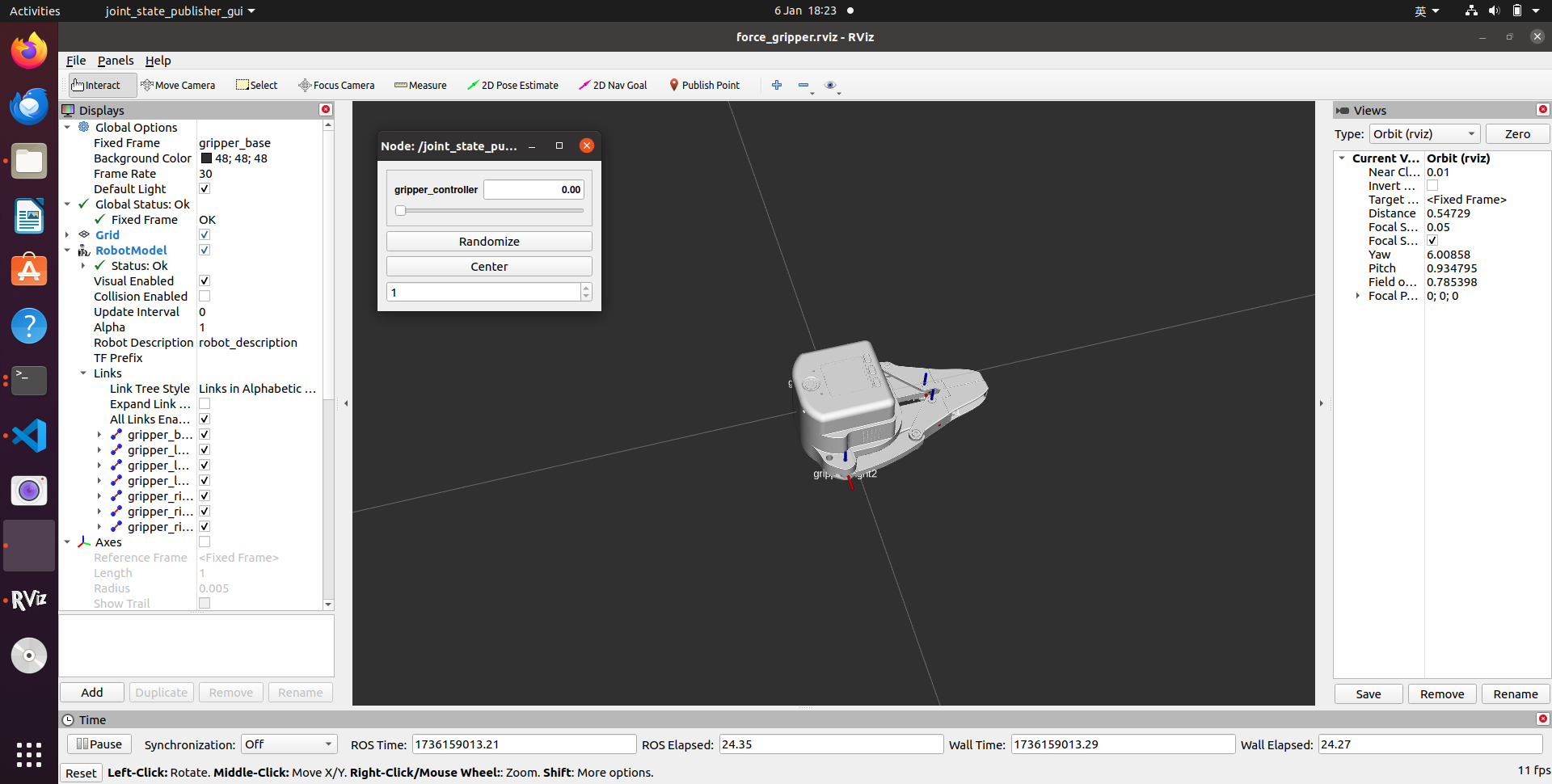
Then you can control the model in rviz by dragging the slider to open or close it. If you want the real gripper to open or close with the model, you need to open another terminal command line and run:
# Make sure to grant serial port permissions before running. The default serial port is /dev/ttyACM0 and the baud rate is 115200. You can modify it according to the actual serial port.
rosrun pro_gripper_f100 force_gripper_slider.py _port:=/dev/ttyACM0 _baud:=115200
6 Case Studies
Mycobot320 force-controlled gripper use case, More case content

C3 force-controlled gripper use case
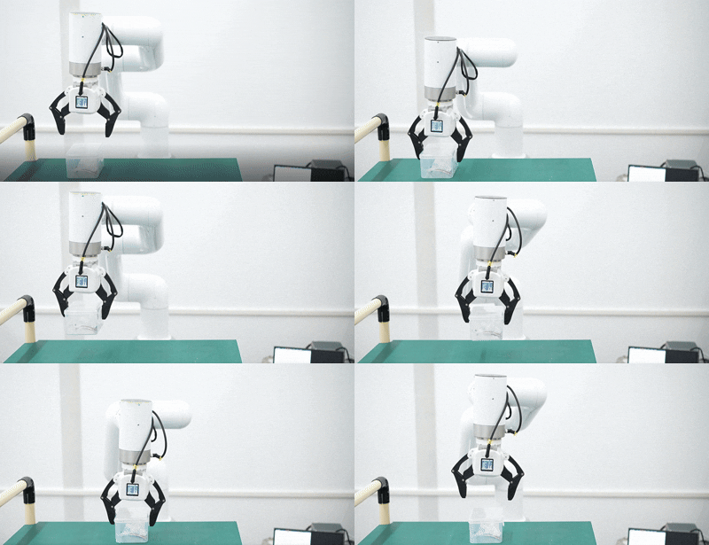
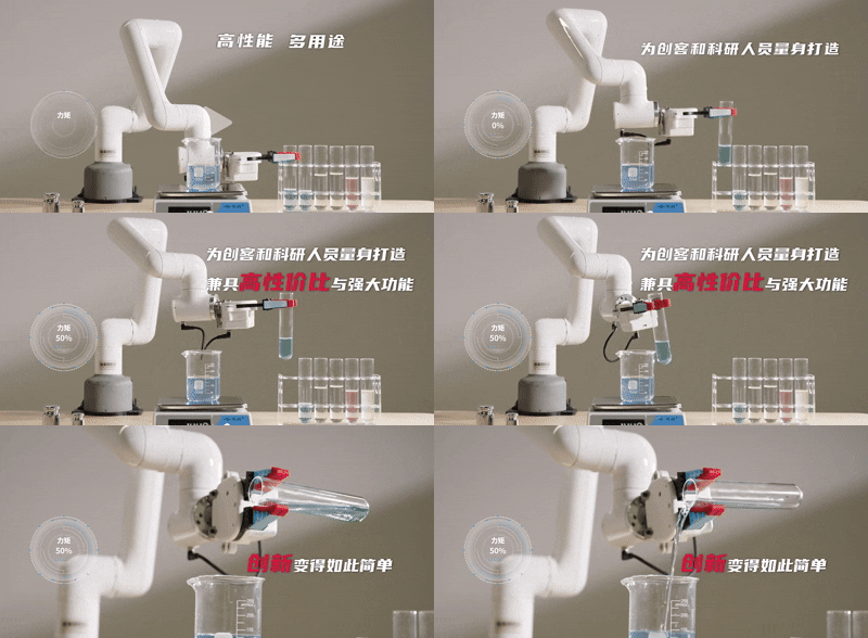
myCobot pro630 force-controlled gripper use case
7 Force Control Gripper ModBus-RTU Protocol
Currently, the ModBus-RTU protocol of the force control gripper only supports function codes 03 and 06. The force control gripper is used as a ModBus-RTU slave, and the register length of the read function code 03 is only 1. The function code 03 represents read, and the function code 06 represents write
Read the holding register (function code 0x03)
Take the example of reading the gripper opening angle
Master request frame format:
| Slave address | Function code | Register address (high bit) | Register address (low bit) | Number of registers (high bit) | Number of registers (low bit) | CRC16 check high bit | CRC16 check low bit |
|---|---|---|---|---|---|---|---|
| 0x0E | 0x03 | 0x00 | 0x0C | 0x00 | 0x01 | crc1 | crc2 |
Slave response frame format:
| Slave address | Function code | Number of bytes | Register (high bit) | Register (low bit) | CRC16 check high bit | CRC16 check low bit |
|---|---|---|---|---|---|---|
| 0x11 | 0x03 | 0x02 | 0x00 | 0x64 | crc1 | crc2 |
Set holding register (function code 0x06)
Set the jaw opening angle as an example Master request frame format:
| Slave address | Function code | Start register (high bit) | Start register (low bit) | Data content (high bit) | Data content (low bit) | CRC16 check high bit | CRC16 check low bit |
|---|---|---|---|---|---|---|---|
| 0x0E | 0x06 | 0x00 | 0x0B | 0x00 | 0x64 | crc1 | crc2 |
Slave response frame format:
| Slave address | Function code | Start register (high bit) | Start register (low bit) | Data content (high bit) | Data content (low bit) | CRC16 check high bit | CRC16 check low bit |
|---|---|---|---|---|---|---|---|
| 0x0E | 0x06 | 0x00 | 0x0B | 0x00 | 0x01 | crc1 | crc2 |
Register table
| Register function | Register address | Read/write permission | Description |
|---|---|---|---|
| Read the firmware main version number | 1 | Read | Version number*10 returns, starting from 1.0. For example, 1.0 returns 10 |
| Read the firmware minor version number | 2 | Read | 0-255. Each time the major version number remains unchanged, submit the test minor version number + 1 |
| Set device ID number | 3 | Write | 1 - 254 |
| Read device ID number | 4 | Read | Return ID |
| Set 485 baud rate | 5 | Write | 0 - 115200 (default) 1 - 1000000 2 - 57600 3 - 19200 4 - 9600 5 - 4800 |
| Read 485 baud rate | 6 | Read | 0 - 115200 1 - 1000000 2 - 57600 3 - 19200 4 - 9600 5 - 4800 |
| Set the gripper enable status | 10 | Write | 0 - Enable off 1 - Enable on |
| Set the gripper angle | 11 | Write | Angle value: 0-100 |
| Read the gripper angle | 12 | Read | Angle value: 0-100 |
| Set the gripper zero position | 13 | Write | 0 - Failed 1 - Success |
| Read the gripper clamping status | 14 | Read | 0 - Moving 1 - Stopped, no object detected 2 - Stopped, object detected 3 - After detecting that the object is clamped, the object falls |
| Set the gripper P value | 15 | Write | Value range 0-254 |
| Read the gripper P value | 16 | Read | Value range 0-254 |
| Set the gripper D value | 17 | Write | Value range 0-254 |
| Read the gripper D value | 18 | Read | Value range 0-254 |
| Set the gripper I value | 19 | Write | Value range 0-254 |
| Read the gripper I value | 20 | Read | Value range 0-254 |
| Set the gripper clockwise operable error | 21 | Write | Value range 0-16 |
| Read the gripper clockwise Runnable error | 22 | Read | Value range 0-150 |
| Set the counterclockwise runnable error of the gripper | 23 | Write | Value range 0-16 |
| Read the counterclockwise runnable error of the gripper | 24 | Read | Value range 0-150 |
| Set the minimum starting force of the gripper | 25 | Write | Value range 0-254 |
| Read the minimum starting force of the gripper | 26 | Read | Value range 0-150 |
| Set torque | 27 | Write | Value range 0-100 |
| Read torque | 28 | Read | Value range 100-300 |
| IO output setting | 29 | Write | Value range :0,1,16,17 |
| Set io opening angle | 30 | Write | Angle value: 0-100 |
| Read io opening angle | 31 | Write | Angle value: 0-100 |
| Set gripper speed | 32 | Write | Speed: 1-100 |
| Read gripper default speed | 33 | Write | Speed: 1-100 |
| Read Io opening angle | 34 | Write | Angle value: 0-100 |
| Read Io closing angle | 35 | Write | Angle value: 0-100 |
| Set absolute angle | 36 | Write | Angle value: 0-100 |
| Pause motion | 37 | Write | Value: 0 |
| Resume motion | 38 | Write | Value: 0 |
| Stop motion | 39 | Write | Value: 0 |
| Get the amount of data in the current queue | 40 | Read | Return the amount of data in the current absolute control queue |
| Set the servo virtual position value | 41 | Write | Value: 0-100 |
| Read the servo virtual position value | 42 | Read | Value: 0-100 |
| Set the clamping current | 43 | Read | Value: 100-300 |
| Read the clamping current | 44 | Read | Value: 1-300 |