Robot knowledge
This chapter is excerpted from Introduction to robotics mechanics and control by J.Craig. If you want to read more about it, please buy it online.
1 Robotics Background
The history of industrial automation is characterized by the rapid evolution of technological approaches. Whether viewed as a cause or consequence of global economic development, these technological advancements are closely intertwined with the global economy. Industrial robots were undoubtedly unique devices in the 1960s. Their integration with computer-aided design (CAD) and computer-aided manufacturing (CAM) systems is the latest development in modern manufacturing automation. These technologies are leading industrial automation into a new realm.
Manipulators are the most important type of industrial robot. Whether they can be called industrial robots is controversial. The equipment shown in the figure is generally considered to fall under the category of industrial robots, while numerically controlled (NC) grinding machines are generally excluded.
Place an ABB robotic arm
Generally speaking, the study of the mechanism and control theory of manipulators is not a new discipline; it is simply a synthesis of traditional disciplines. Mechanical engineering theory provides a methodology for studying manipulators in static and dynamic environments; mathematical methods are used to describe the spatial motion and characteristics of manipulators; control theory provides various design methods and evaluation algorithms for achieving desired motions or forces; electrical engineering techniques are used to design sensors and industrial robot interfaces; and computer technology provides the programming platform necessary to perform desired tasks.
2 Basic Concepts of Robotics
Robotic Arm
A robotic arm can also be called an industrial robot, collaborative robot, manipulator, bionic arm, or serial arm.
Position Description
In robotics research, we typically study the position of objects in three-dimensional space. These objects include the manipulator's rods, components, and grippers, as well as other objects within the manipulator's workspace. These objects can typically be described by two key properties: position and posture. Naturally, we first study how to represent and calculate these parameters mathematically.
To describe the position and posture of an object in space, we typically first place the object in a fixed spatial coordinate system, or reference system. We then study the object's position and posture within this reference system.
Forward Kinematics of Manipulators
Kinematics studies the motion of an object without considering the forces causing that motion. In kinematics, we study position, velocity, acceleration, and higher-order derivatives of position variables with respect to time or other variables. Thus, the kinematics of manipulators study the full geometric and temporal characteristics of motion. Almost all manipulators are composed of rigid links connected by joints that allow relative motion. These joints are usually equipped with position sensors that measure the relative position of the adjacent links. In the case of rotational joints, this displacement is called the joint angle. Some manipulators contain sliding (or moving) joints. ) joints, then the displacement of two adjacent links is linear motion, sometimes referred to as the joint offset.
A typical problem in manipulator kinematics research is the forward kinematics of the manipulator. Computing the position and orientation of the manipulator's end effector is a static geometric problem. Specifically, given a set of joint angles, the forward kinematics problem involves calculating the position and orientation of the tool coordinate system relative to the base coordinate system. This process is generally referred to as converting the manipulator's position representation from joint space to Cartesian space.
The number of degrees of freedom (DOF) is the number of independent degrees of freedom (DOFs) in the manipulator. Figure 1-5 The number of position variables of the manipulator in a coordinate system (reference frame) that determine the positions of all components in the mechanism. Degrees of freedom are universal to all mechanisms. For example, a four-bar linkage has only one degree of freedom (even though it has three movable members). For a typical industrial robot, since the manipulator is mostly an open kinematic chain, and each joint position is defined by an independent variable, the number of joints equals the number of degrees of freedom.
The end effector is attached to the free end of the manipulator. Depending on the robot's application, the end effector can be a gripper, a welding gun, an electromagnet, or other device. The position of the manipulator is typically described using a tool coordinate system attached to the end effector. The tool coordinate system corresponds to the base coordinate system associated with the manipulator's fixed base.
Manipulator Inverse Kinematics: Given the position and orientation of the manipulator's end effector, calculate all joint angles that can achieve the given position and orientation.
3 Spatial Description
Position
Once a coordinate system is established, we can locate any point in the world coordinate system using a 3x1 position vector. Because multiple coordinate systems are often defined within the world coordinate system, the position vector must be appended with information indicating the coordinate system in which it is defined. In this book, position vectors are prefixed with a superscript to indicate the coordinate system they refer to.
A coordinate system {A} is represented by three mutually orthogonal unit vectors with arrows. A point AP is represented by a vector, which can be equivalently considered a position in space, or simply represented by a sequence of three numbers. Vector Diagram 2-1: Vectors relative to a coordinate system (example). The individual elements are designated by the subscripts x, y, and z:
Posture
We often find it necessary not only to represent points in space but also to describe the posture of objects in space. For example, if the vector "P" in Figure 2-2 directly identifies a point between the fingertips of the manipulator, the position of the hand can only be fully determined if the pose of the hand is known. Assuming the manipulator has a sufficient number of joints, the hand can assume any pose, while the position of the point between the fingertips remains unchanged. To describe the pose of an object, we fix a coordinate system on the object and express this coordinate system relative to a reference system. In Figure 2-2, the coordinate system {B} is fixed to the object in some way. The description of {B} relative to {A} is sufficient to express the pose of the object (A).
Coordinate System A reference system can be described by the relationship of one coordinate system to another. A reference system encompasses the concepts of position and pose, and is often considered a combination of these two concepts. Position can be expressed by a reference system whose rotation matrix is the identity matrix and whose position vector in this reference system specifies the position of the described point. Similarly, if the position vector in the reference system is the zero vector, it represents the pose.
4 DH Parameters
Definition For revolute joint n, set 0 = 0.0. At this point, the X-axis and X,-axis are in the same direction. The origin of the coordinate system (N) is selected so that d. = 0.0. For translatory joint n, set the directions of the 8 axes so that 0. = 0.0. When d. = 0.0, the origin of the coordinate system (N) is located at the intersection of the XN-1 axis and the joint axis n.
Summary of Link Parameters in the Link Coordinate System: If the link coordinate system is fixed to the link according to the above rules, the link parameters can be defined as follows:
- a_i-1: Along x_i-1: The distance from z_i-1 to z_i
- alpha_i-1: Around x_i-1: The angle from z_i-1 to z_i
- d_i: Along z_i: The distance from x_i-1 to x_i
- theta_i : Around z_i : From x_i-1 to x_i
Here's an article that can help https://blog.csdn.net/hitgavin/article/details/104442034
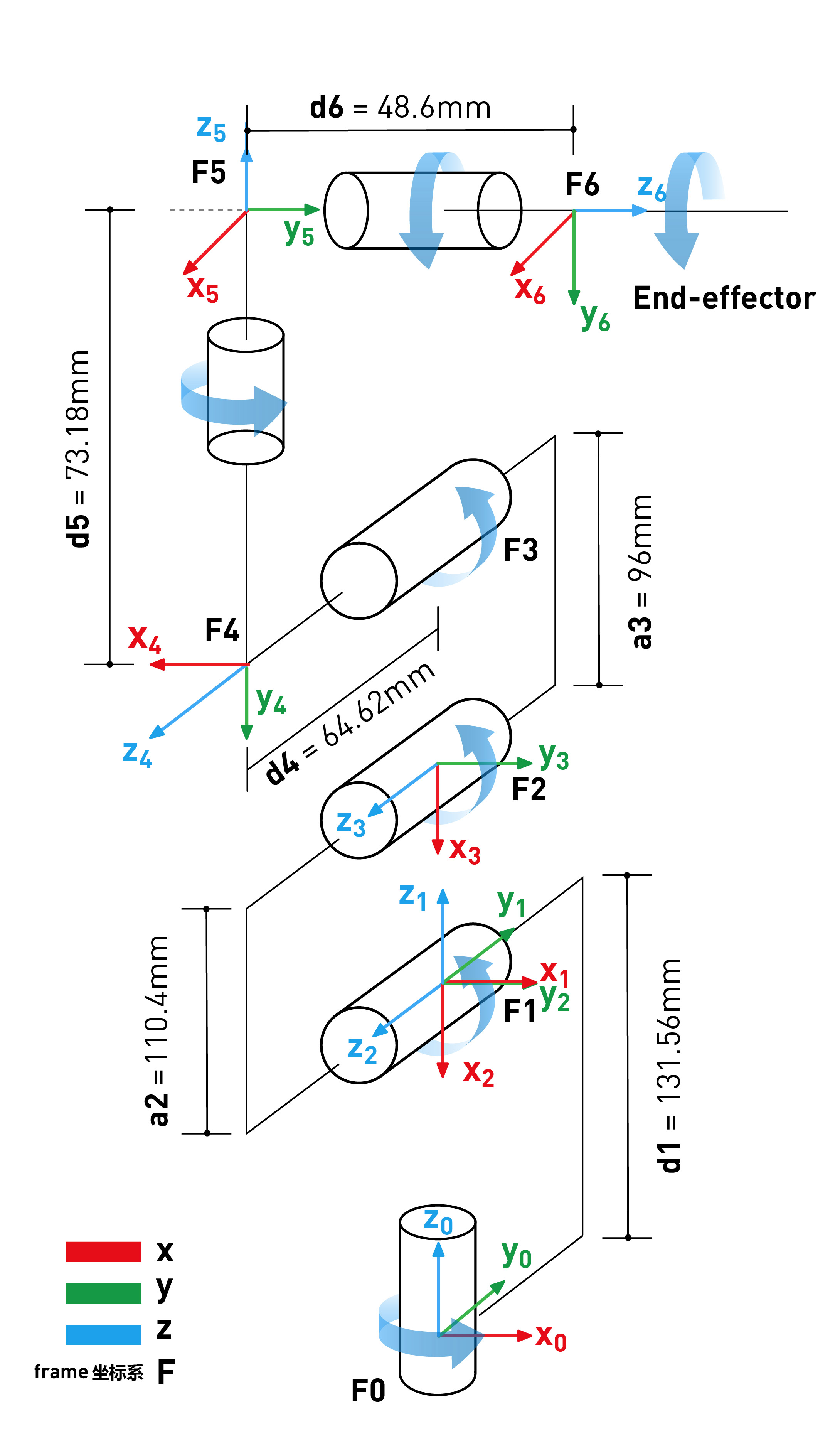
myCobot DH parameters
| Joint | alpha | a | d | theta | offset |
|---|---|---|---|---|---|
| 1 | 0 | 0 | 131.56 | theta_1 | 0 |
| 2 | PI/2 | 0 | 0 | theta_2 | -PI/2 |
| 3 | 0 | -110.4 | 0 | theta_3 | 0 |
| 4 | 0 | -96 | 64.62 | theta_4 | -PI/2 |
| 5 | PI/2 | 0 | 73.18 | theta_5 | PI/2 |
| 6 | -PI/2 | 0 | 48.6 | theta_6 | 0 |