Settings
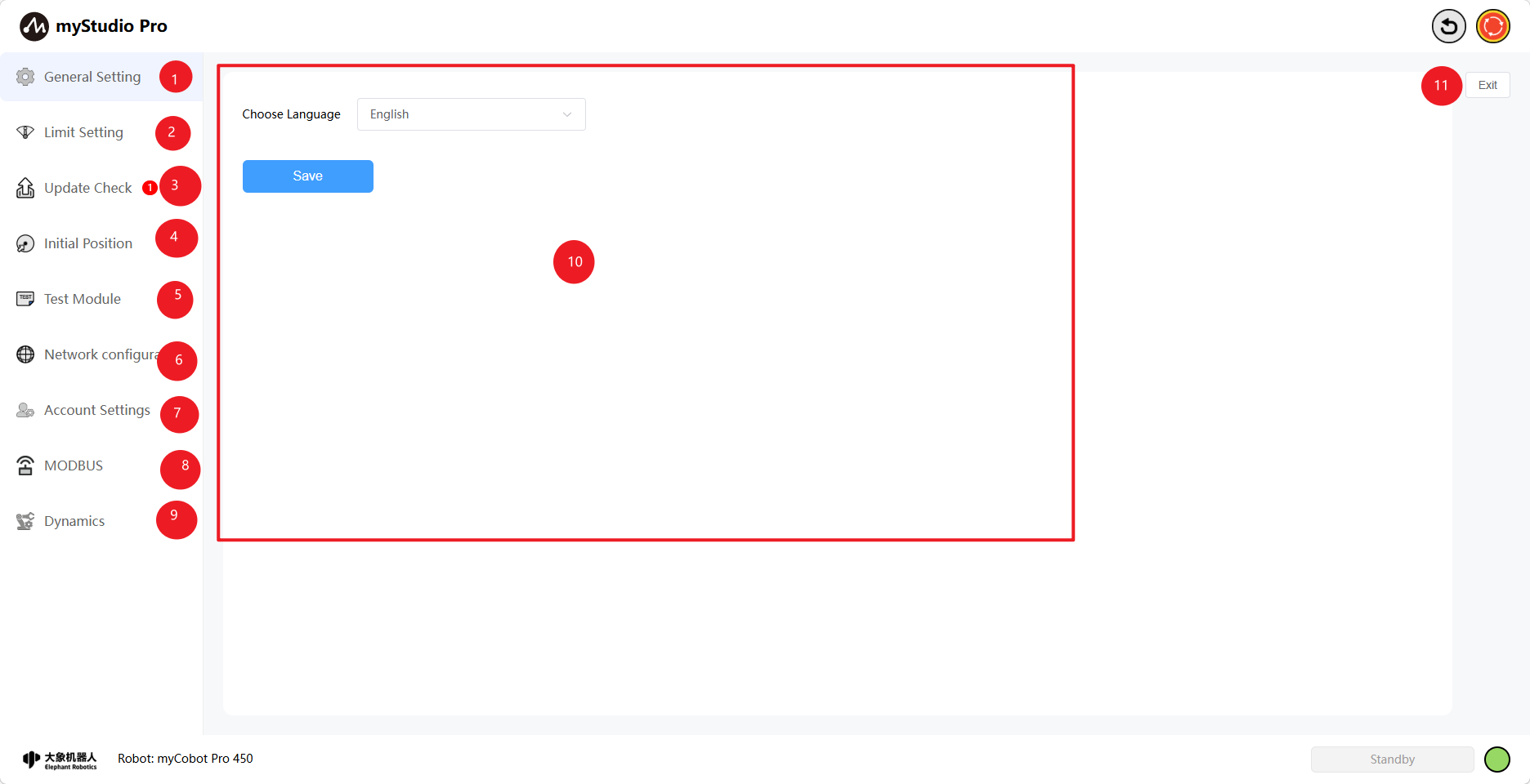
1 Interface Introduction
| Number | Function Introduction |
|---|---|
| 1 | General Settings Module, mainly for setting the language |
| 2 | Limit Setting Module |
| 3 | Check for Updates Module |
| 4 | Initial Attitude Module |
| 5 | Network Configuration Module |
| 6 | Account Settings Module |
| 7 | Test Module |
| 8 | MODBUS Module |
| 9 | Dynamics Module |
| 10 | Module Content Display Area |
| 11 | Exit Settings |
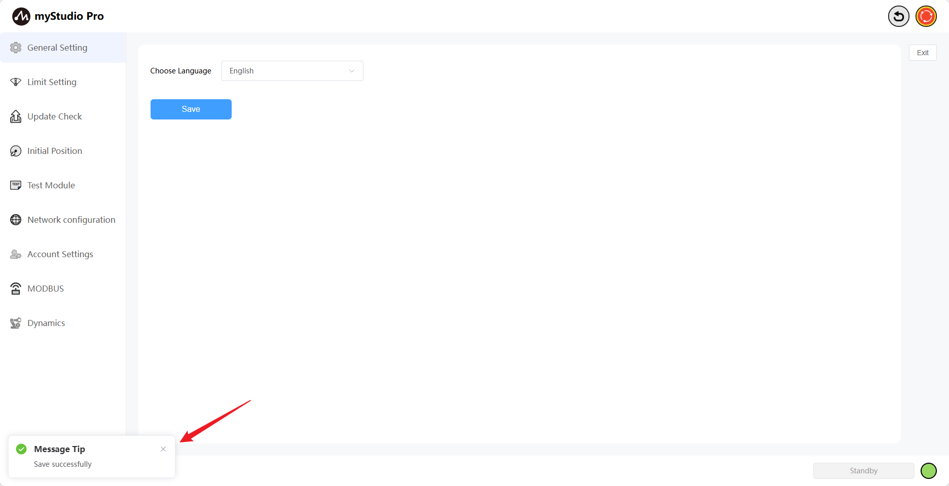
2 General Settings
Click the General Settings icon button to enter the language settings page. Language selection supports Chinese and English.
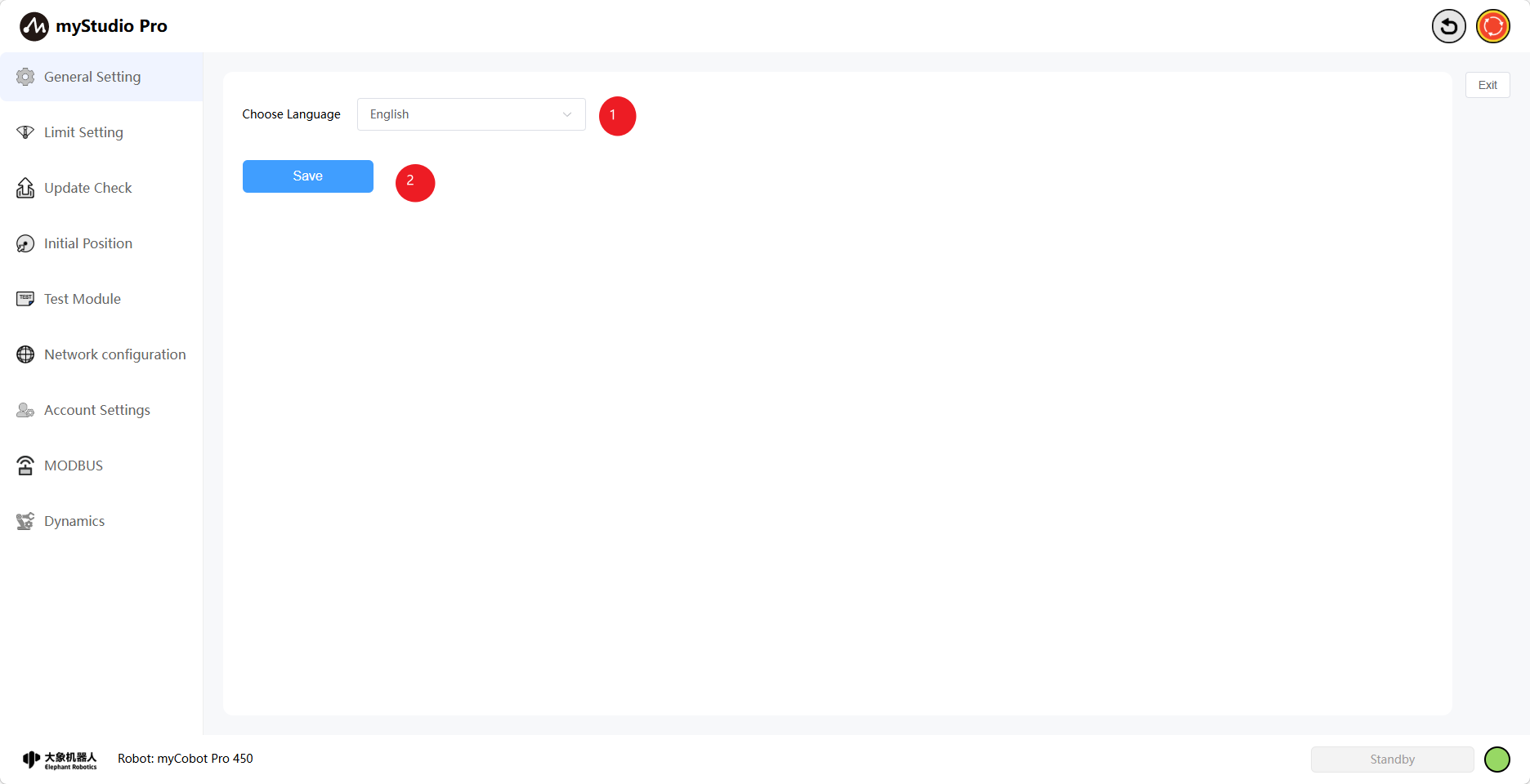
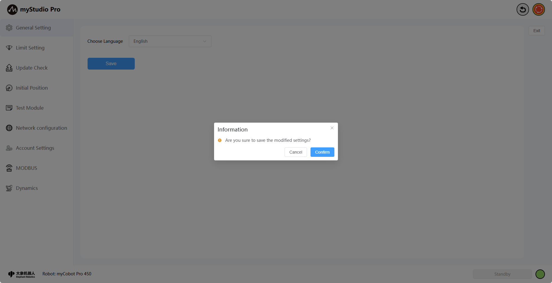
After selecting the corresponding language, click the Save button. A secondary confirmation pop-up window will appear. Click "Confirm" to successfully set the language.
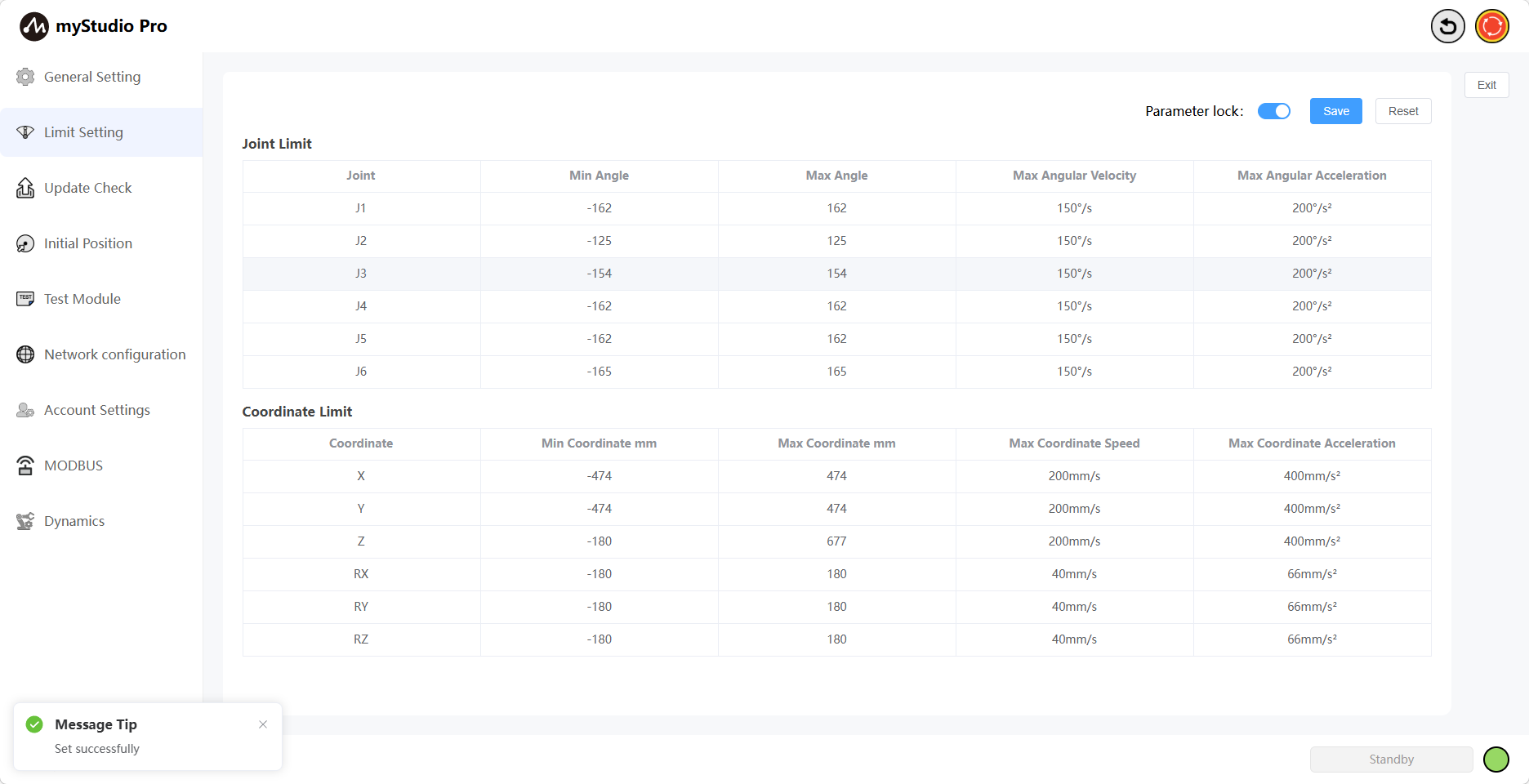
3 Limit Setting
Note: Limit parameter modification only supports the minimum and maximum angles of the joints; other parameters cannot be modified.
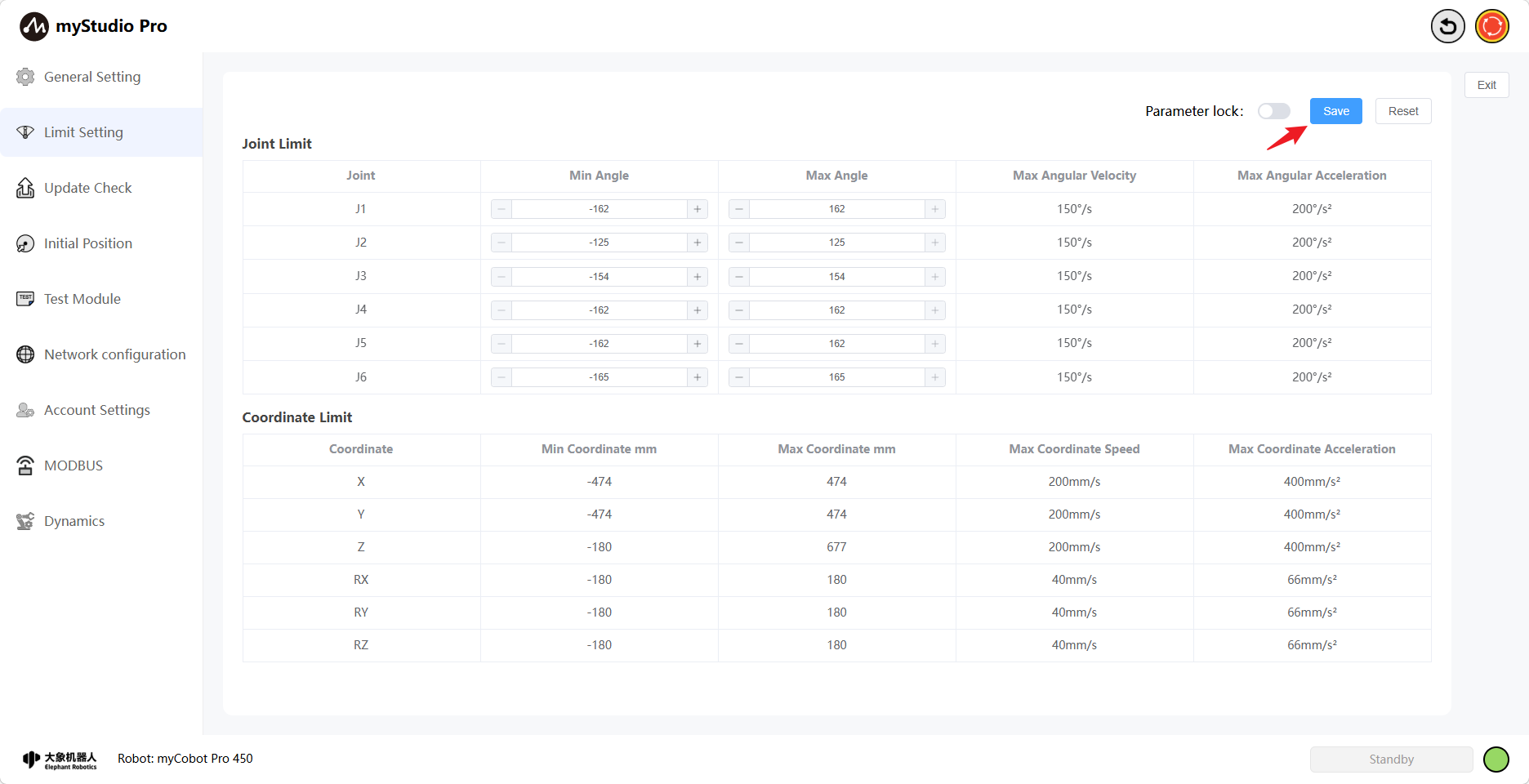
Clicking the Limit Setting icon button will take you to the joint limit settings page. The Limit Setting interface displays the relevant parameters for the current robotic arm's joint limits and coordinate limits by default.
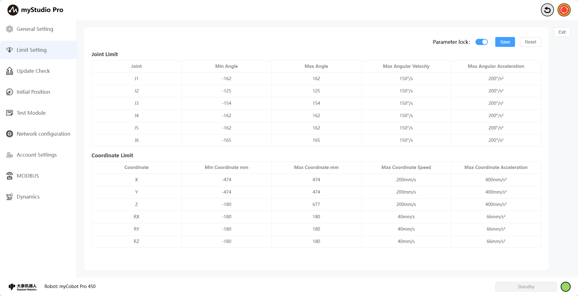
The Parameter Lock button is locked by default, and its color is blue, indicating that the limit parameters cannot be modified.
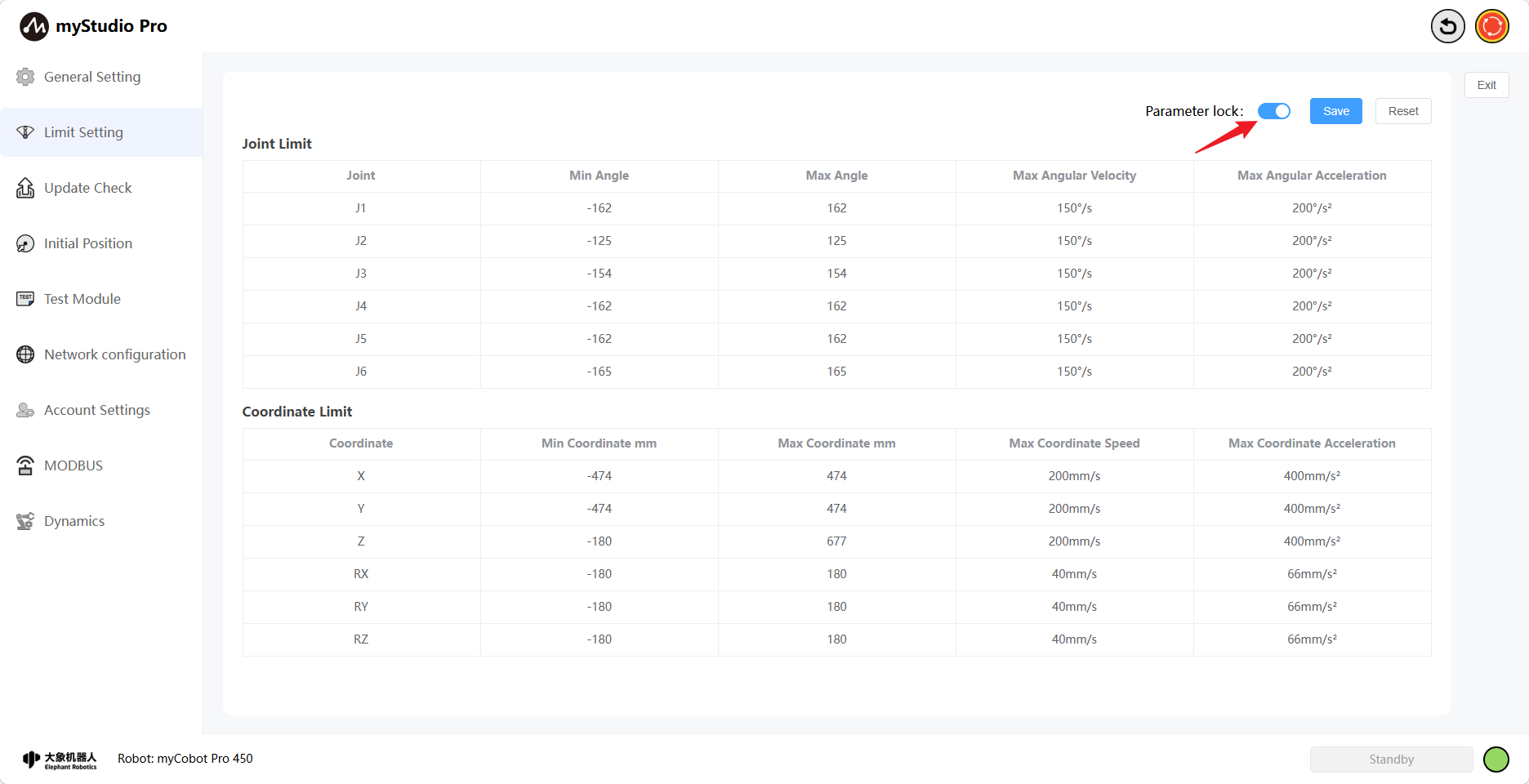
When the parameter is locked, clicking the Parameter Lock button will turn the button gray, indicating that it is unlocked and the limit parameters can be modified (only the minimum and maximum angle values can be changed).
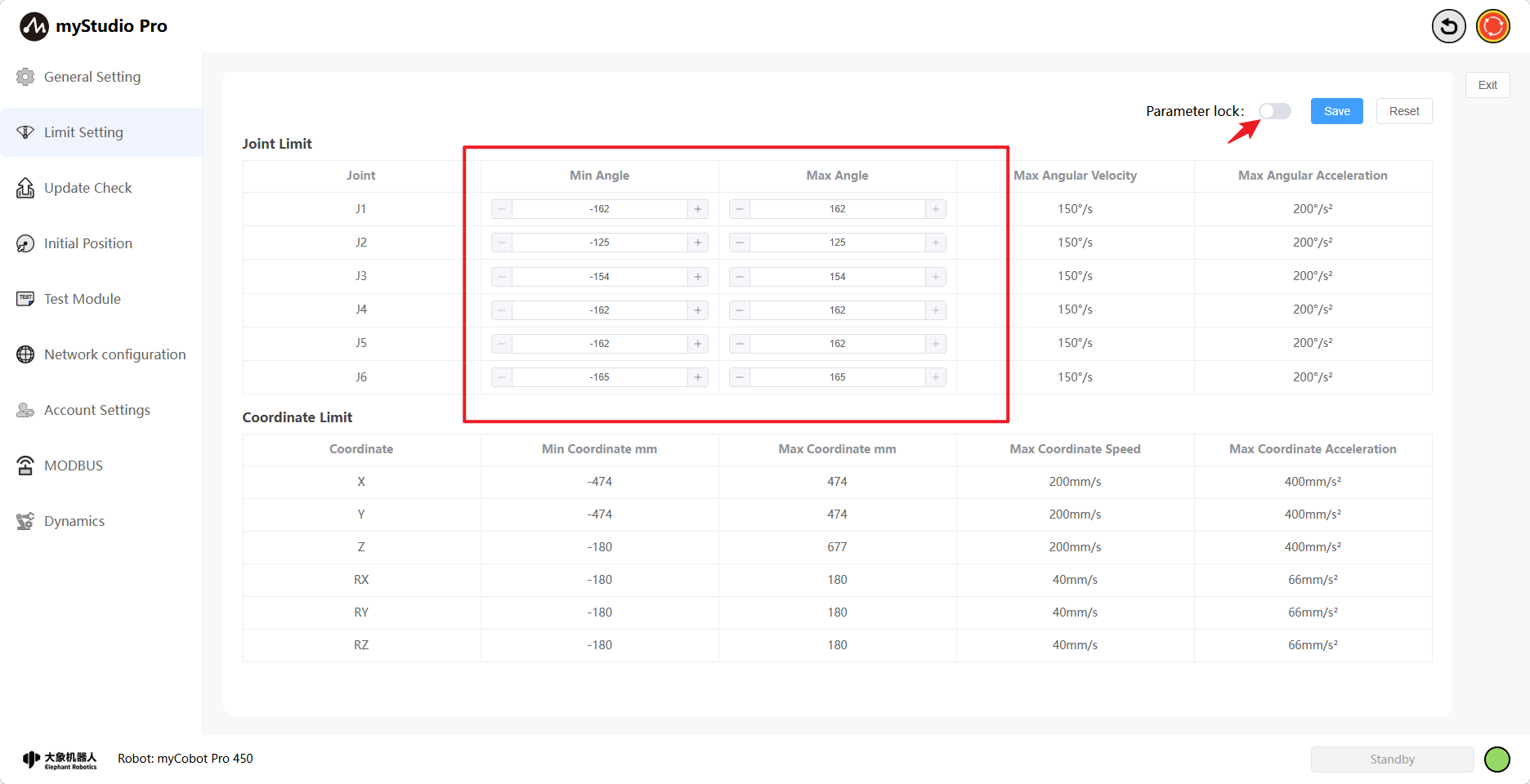
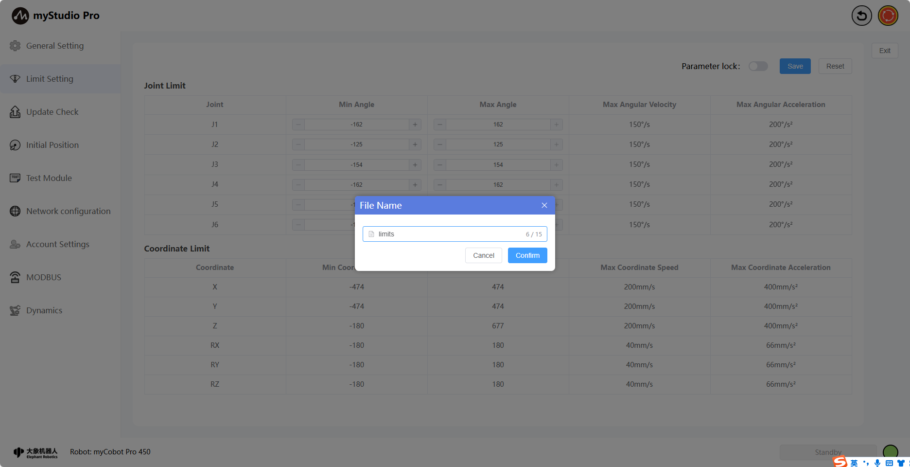
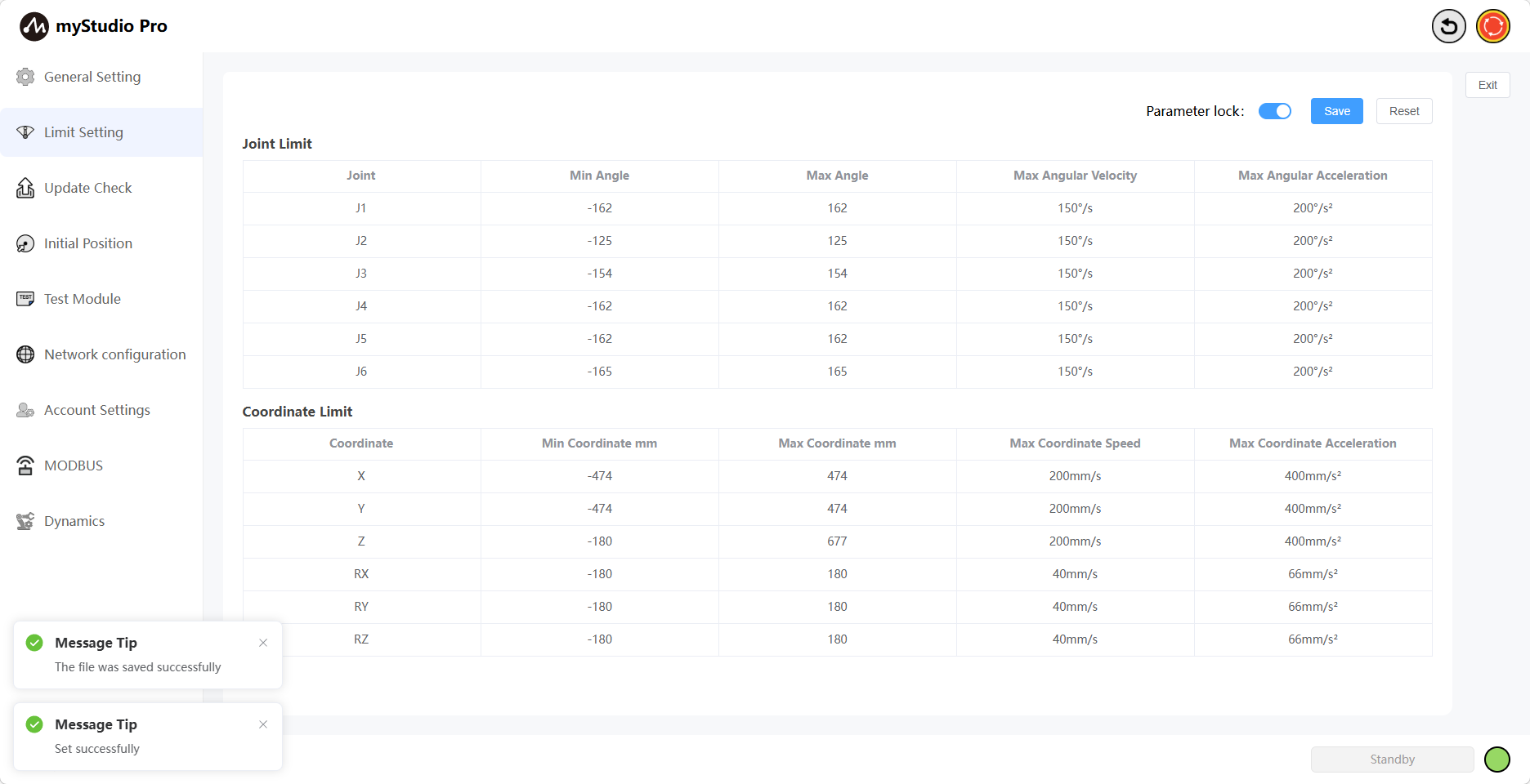
Click the Save button, and define the filename according to the prompts in the pop-up window. This will save the parameters of the current limit setting page to a local file (JSON file) and set the joint limits of the robotic arm. A message will be displayed on the page after successful setting.
Click the Reset button to restore all joint and coordinate limits to their default settings. A prompt will appear asking if you want to restore default settings.
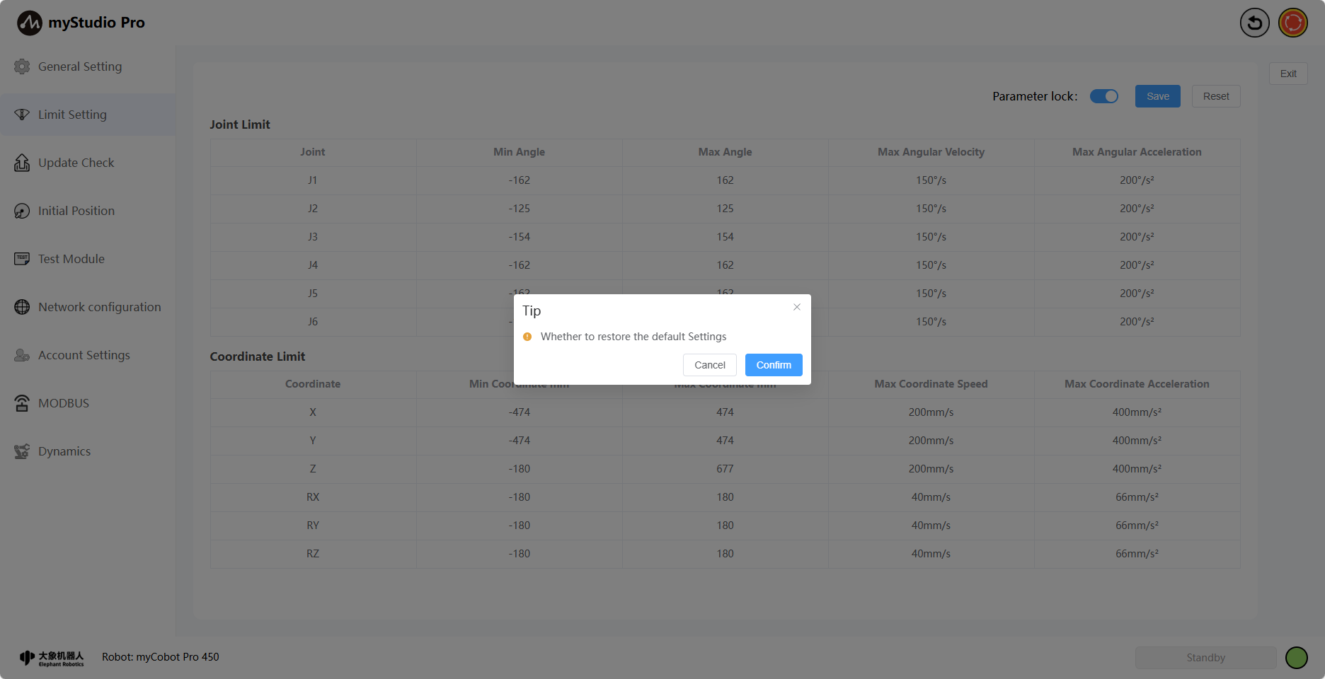
Clicking OK displays the message Setting successful.
4 Check for Updates
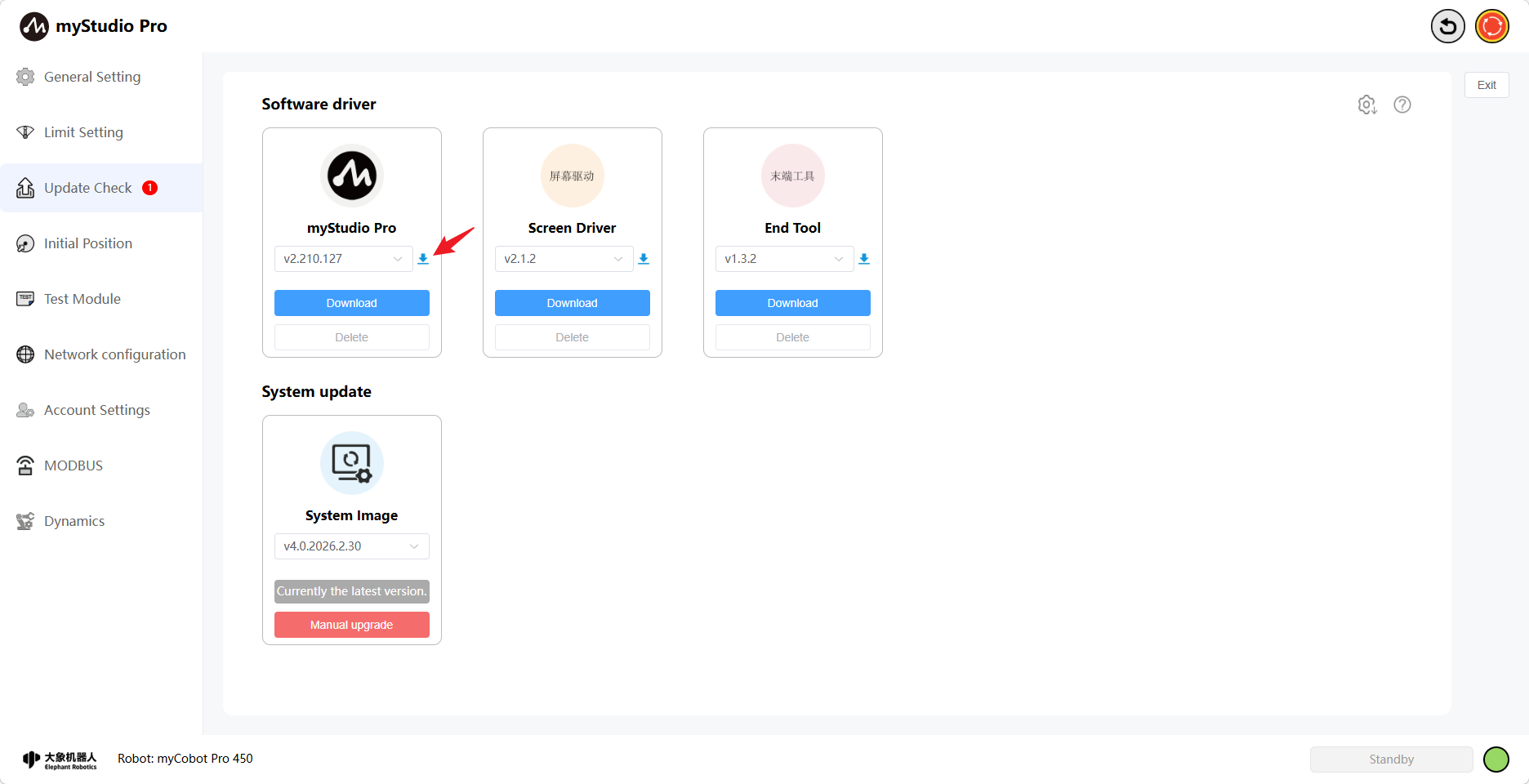
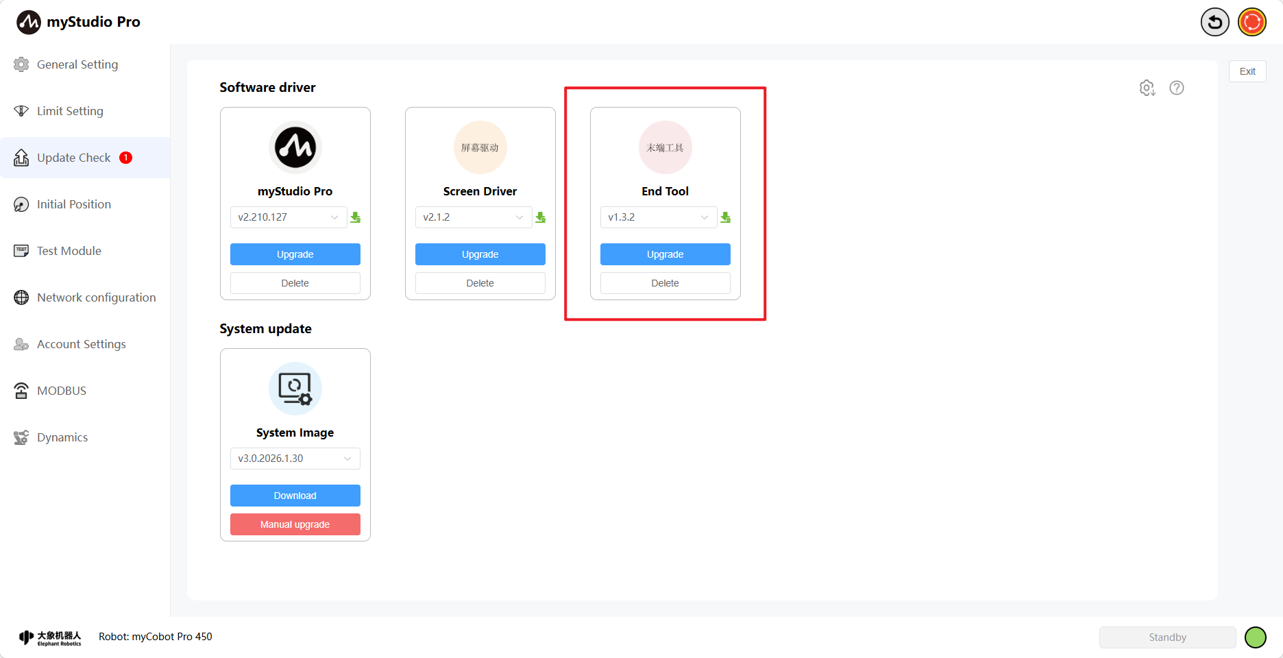
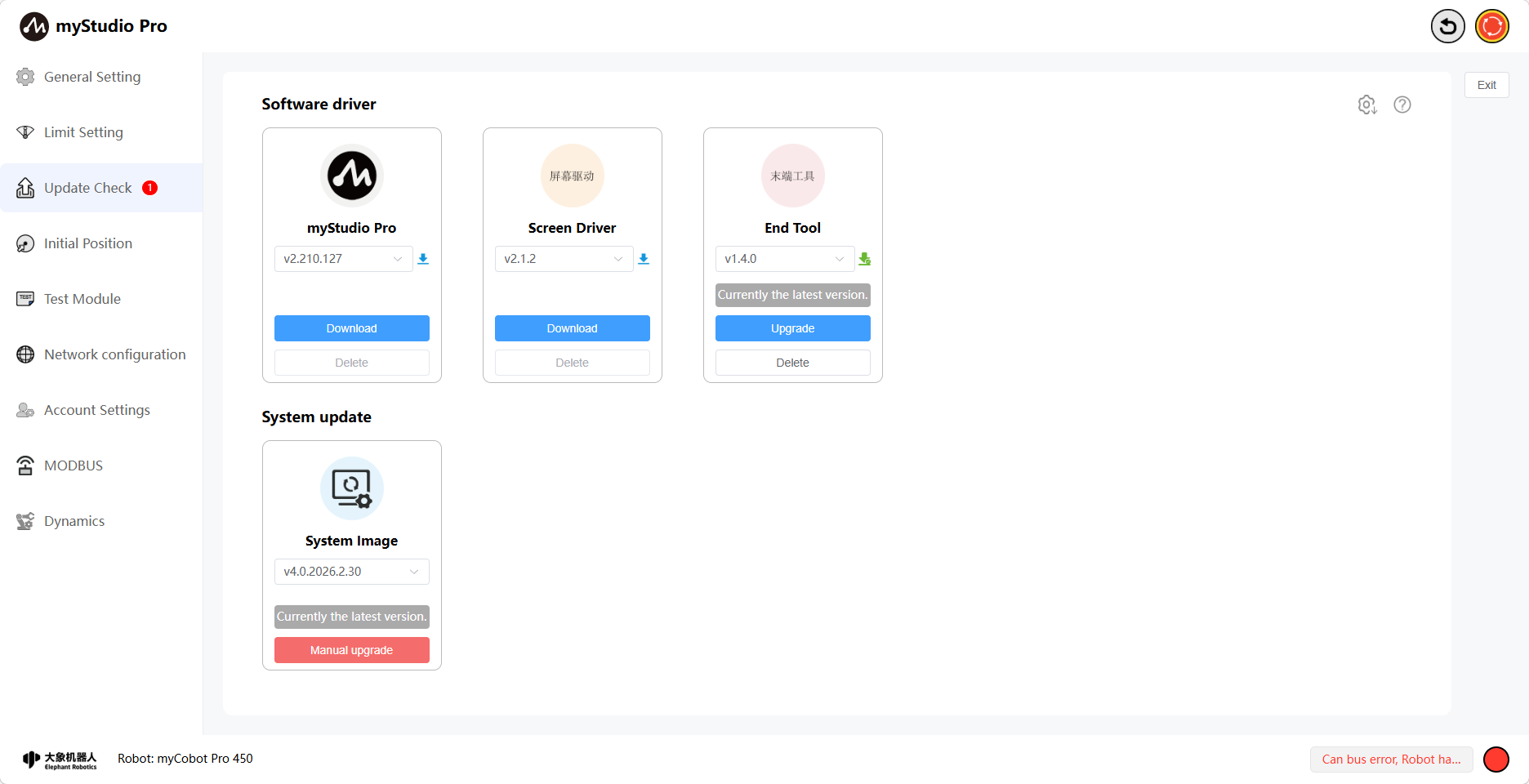
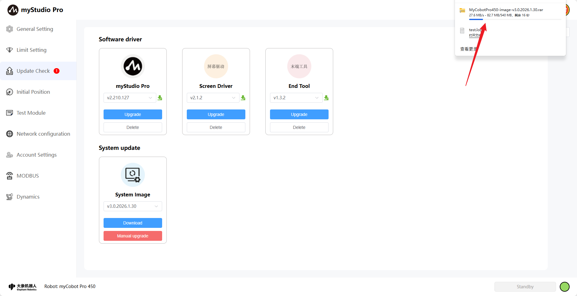
Clicking the Check for Updates icon will take you to the update status page. This page allows you to download, delete, and upgrade software drivers (myStudio Pro, screen driver, terminal tools), and download and manually upgrade system images.
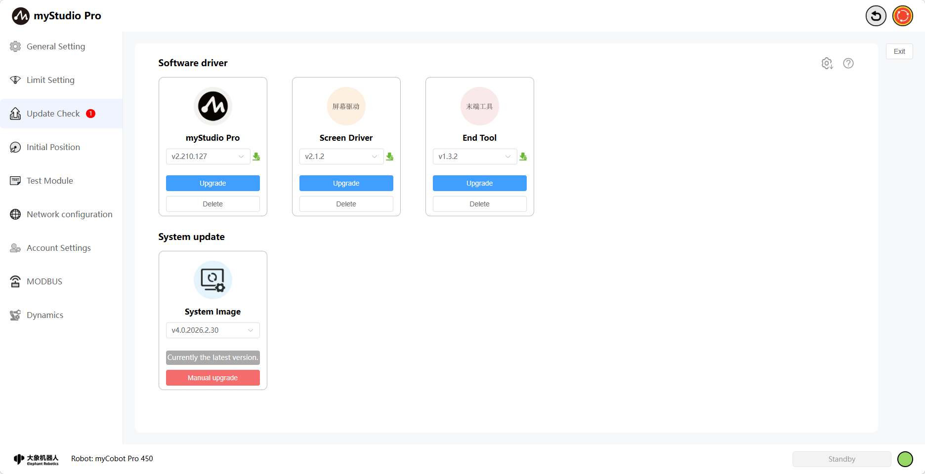
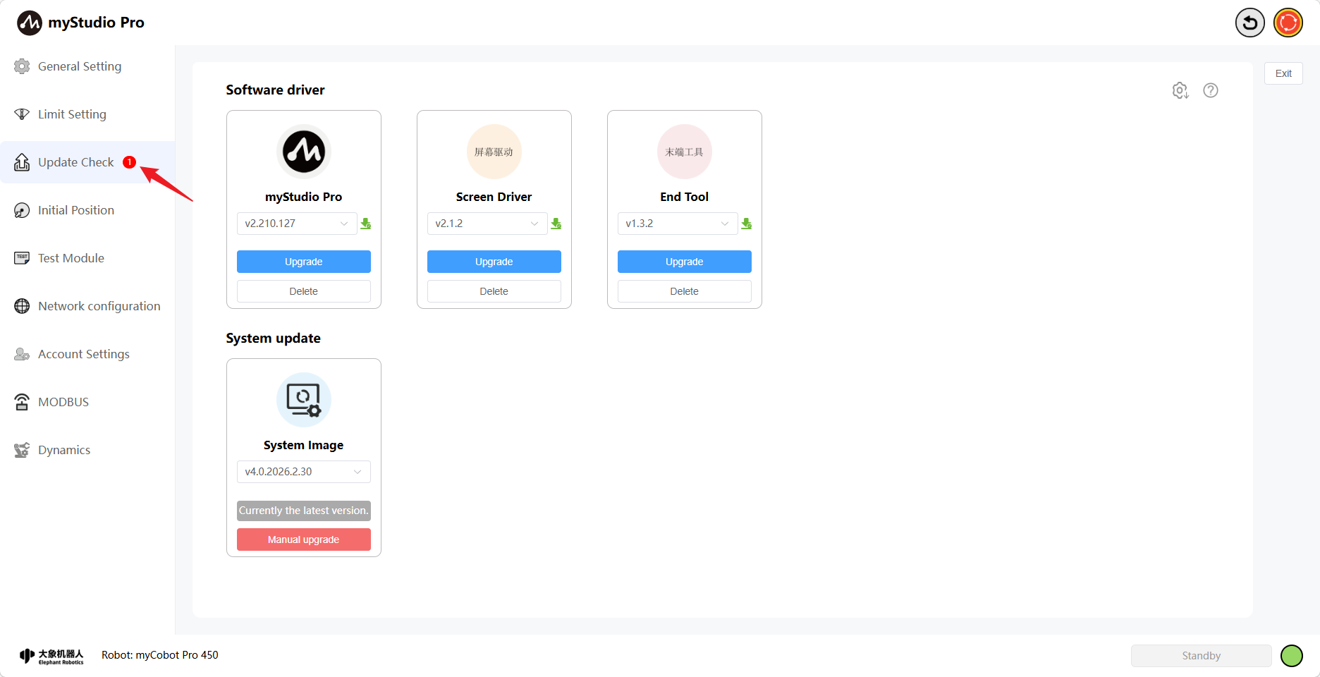
When a newer version of the software driver exists and no update has been performed, the number 1 will appear next to the "Check for Updates" icon, indicating that a new version exists. You can go to this page to view the specific update details.
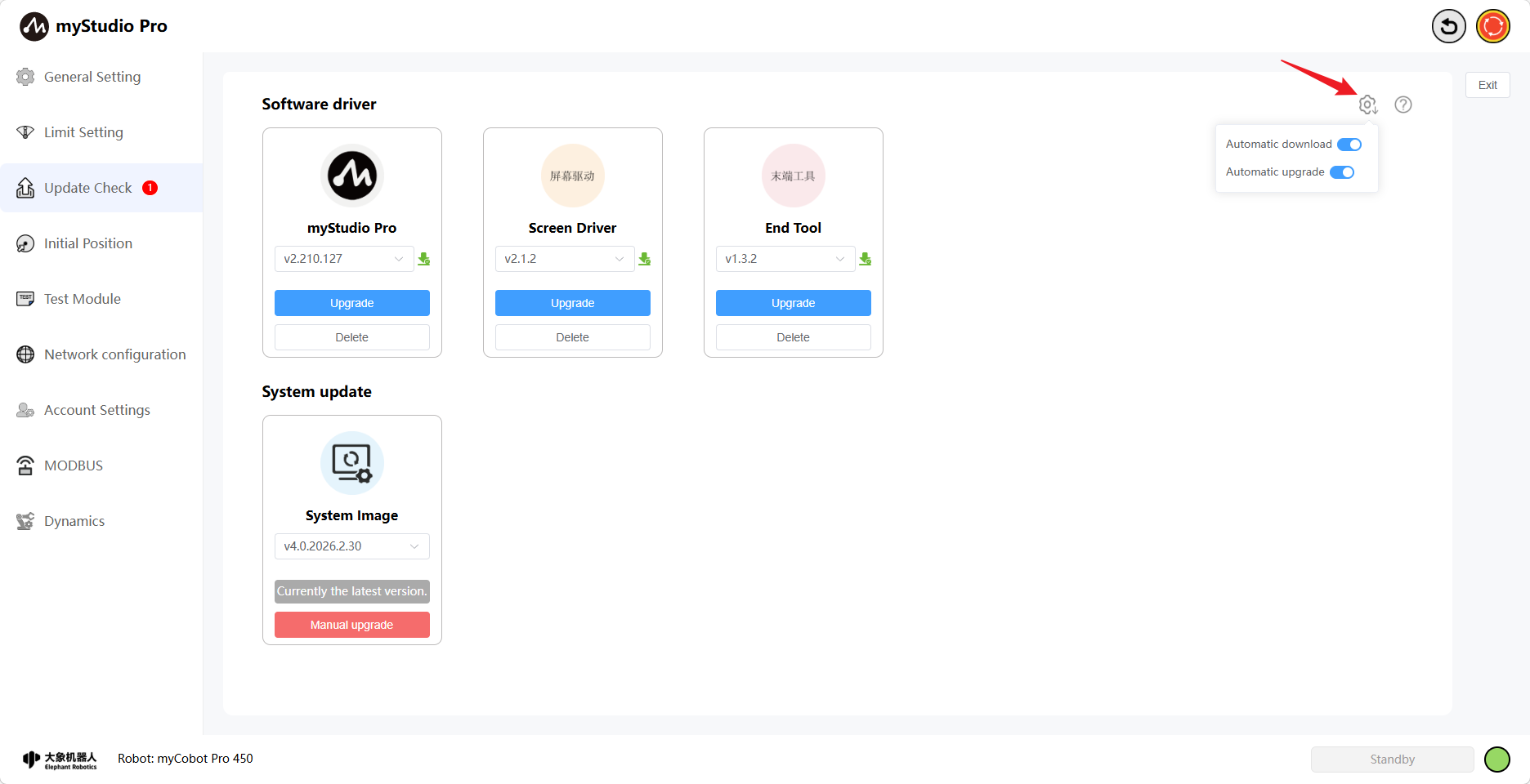
On this page, you can enable the automatic download and automatic update function for software drivers. As the name suggests, automatic download will silently download the latest version of the software driver that needs updating in the background. The automatic update process will only begin after all the software drivers that need to be updated have been downloaded.
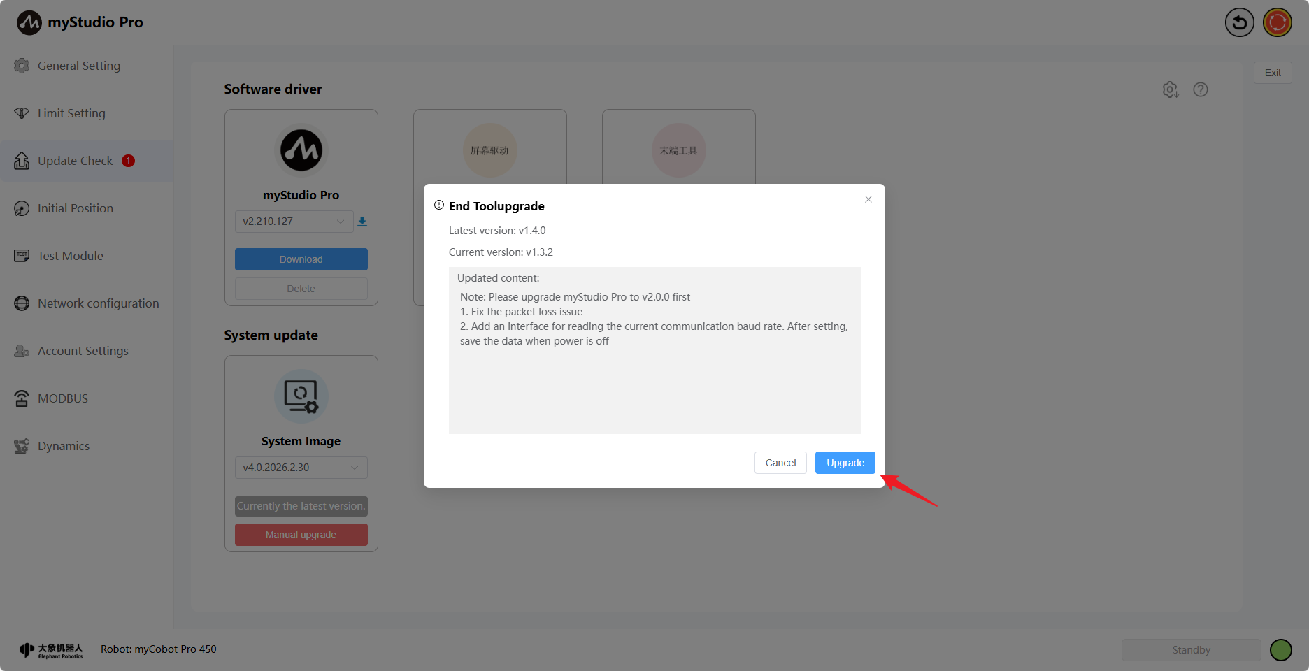
When an automatically updating software driver is available, an update information pop-up will appear on the main page. This pop-up displays the content included in this automatic update.
Note: This pop-up will only appear once during current use. If no update is performed, it will reappear upon subsequent use.
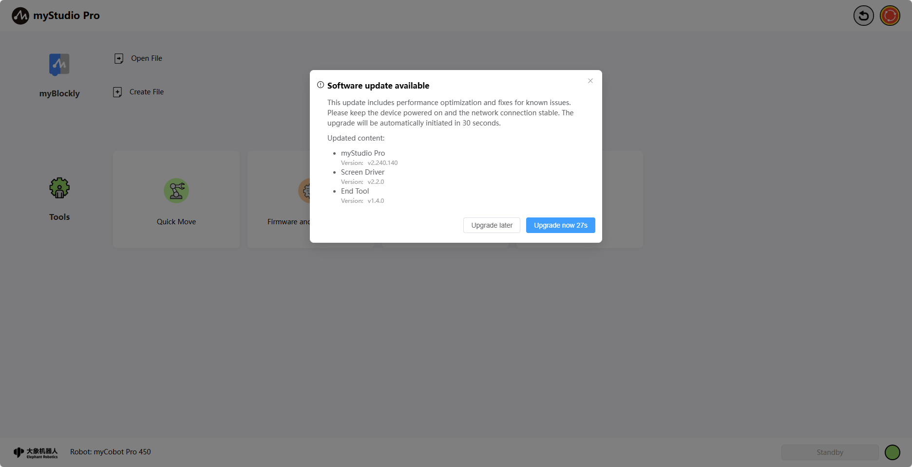
If the pop-up is not closed and the "Upgrade Now" button is clicked within 30 seconds, the update will proceed automatically. Otherwise, the automatic update will not occur. An update loading screen will be displayed during the update process until all update content is completed and the loading screen disappears.
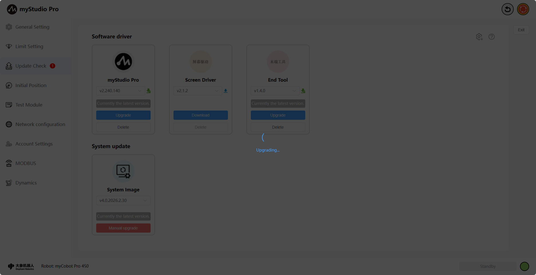
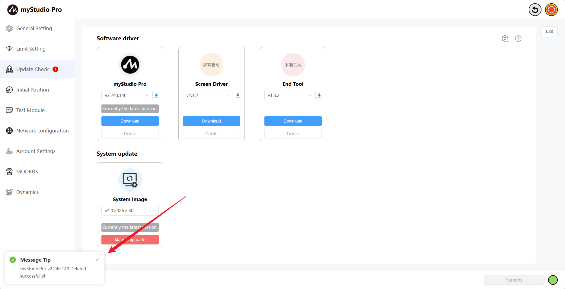
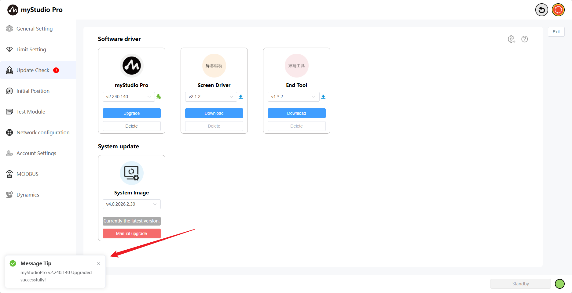
During the automatic update process, a corresponding message will be displayed when each software driver update is completed. The loading indicator will disappear once the last driver update is finished.
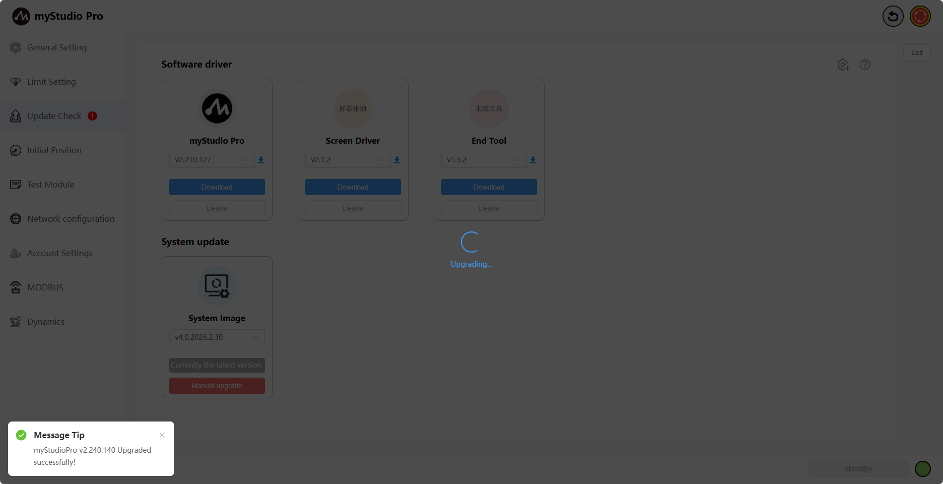

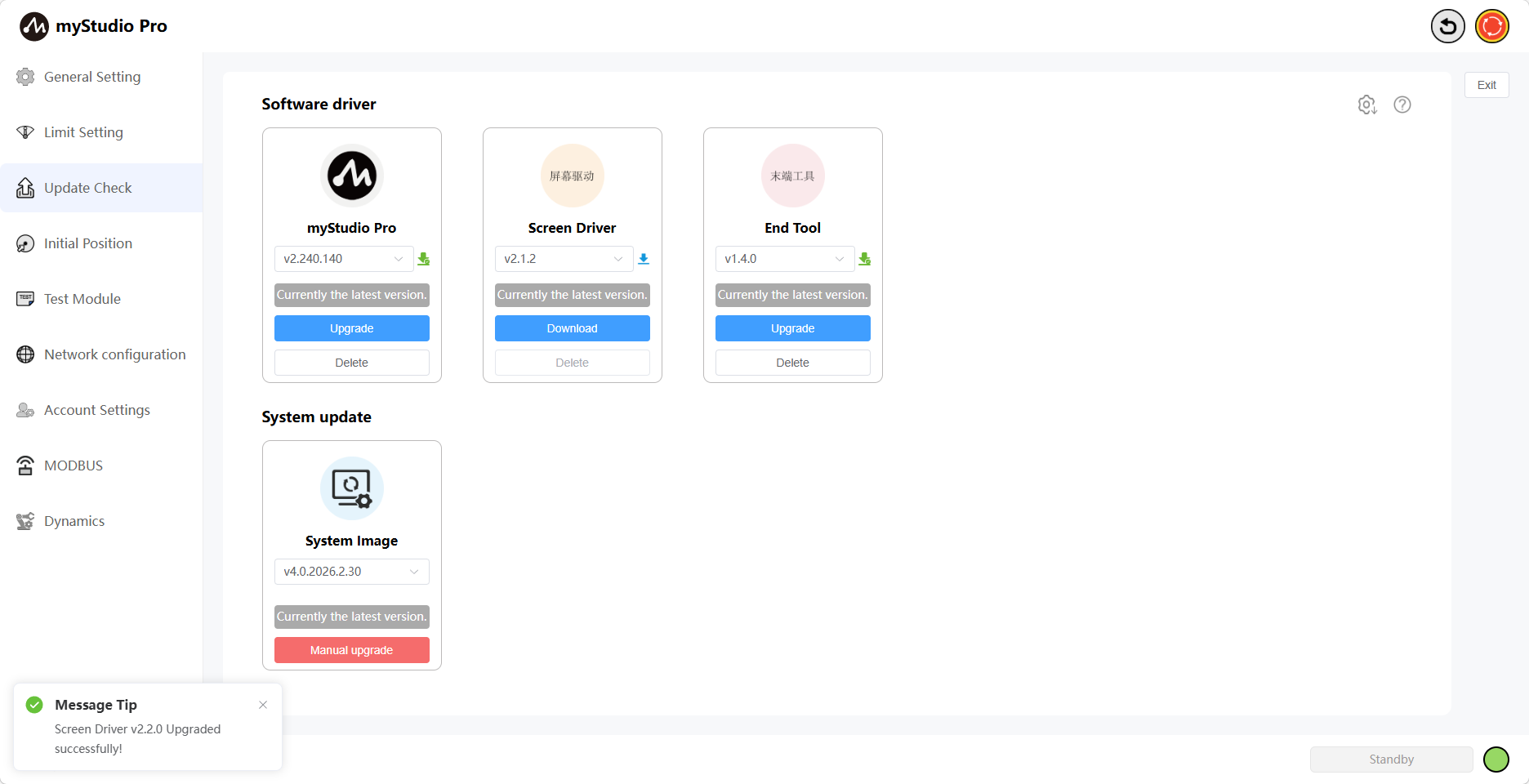
The automatic upgrade process is now complete.
myStudio Pro Upgrade
Feature Introduction:
myStudio Pro

Version Number
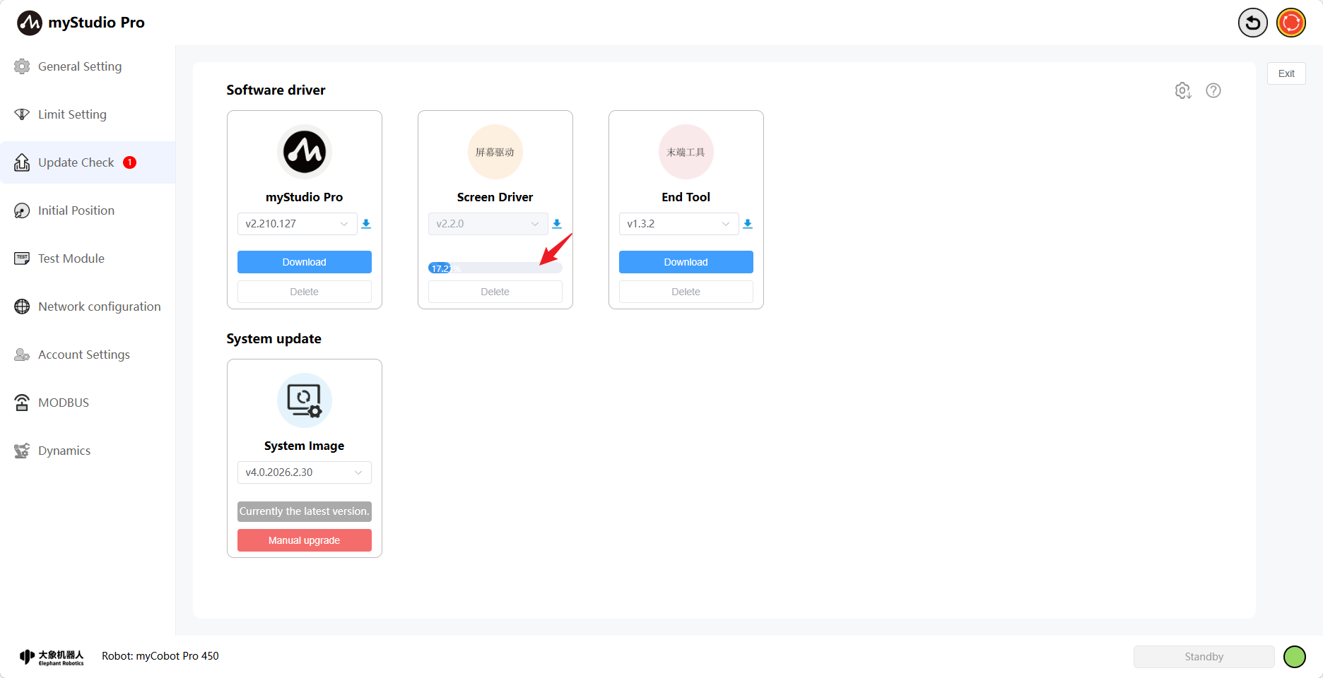
The default is the current version. You can also select another version to download and upgrade. When the selected version is downloading, the icon next to the version number will be blue, and the "Delete" button will be disabled.
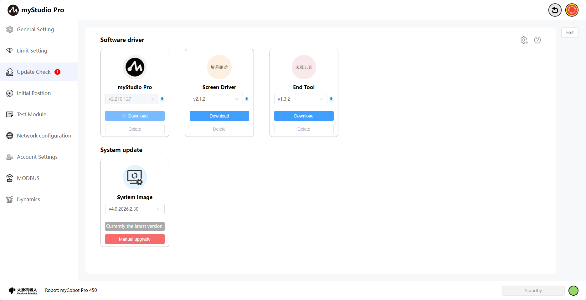
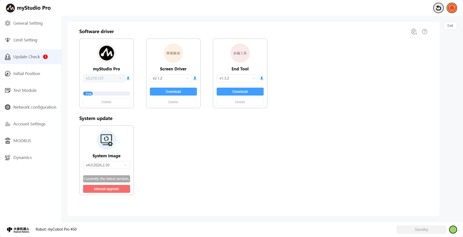
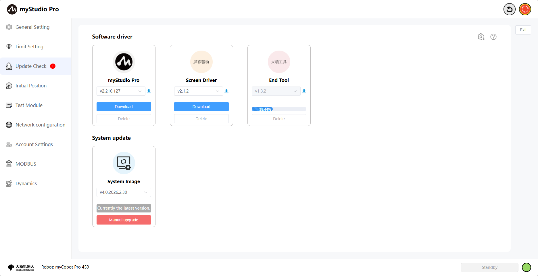
Clicking the "Download" button will download the selected version. The version dropdown selection box and button will be disabled during this process. The download progress will be displayed once it starts.
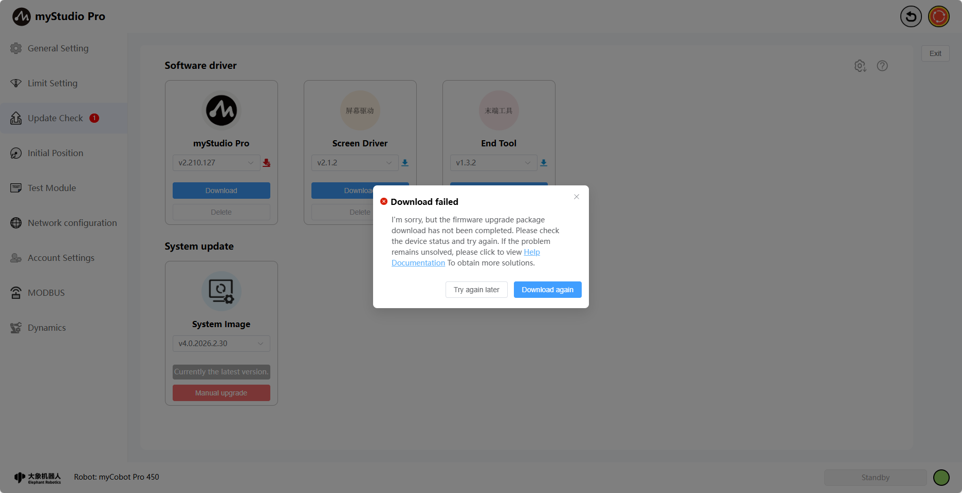
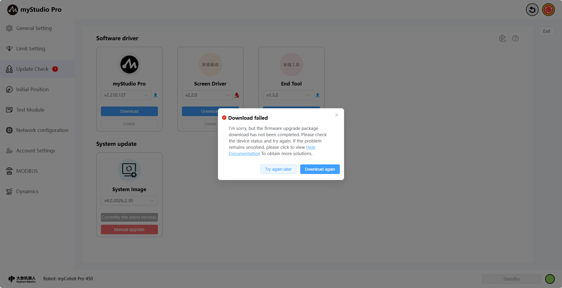
When the download fails, a failure pop-up will appear and the icon will turn red. Clicking the "Re-download" button will re-download all previously failed drivers.
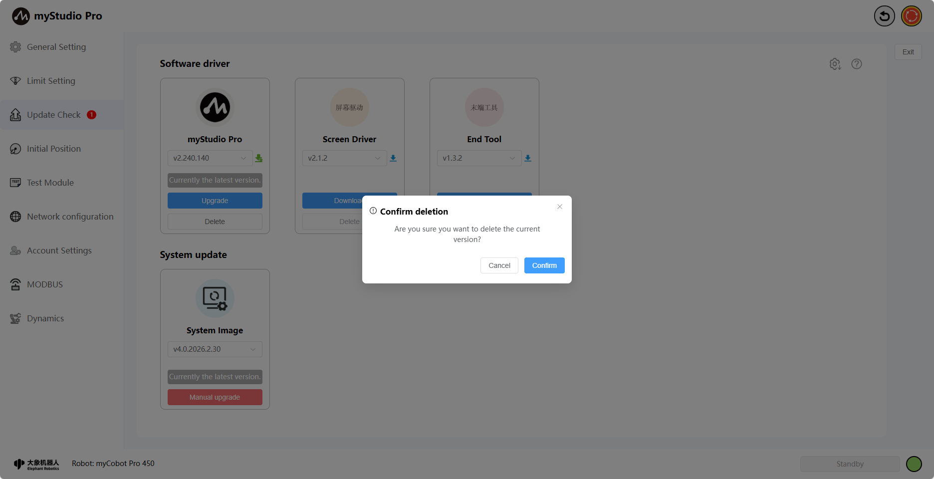
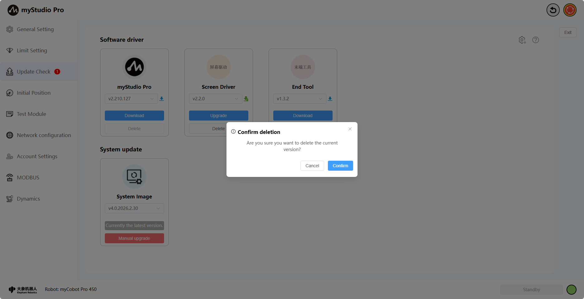
Clicking the "Delete" button will bring up a confirmation window. Clicking "Confirm" will delete the downloaded drivers.
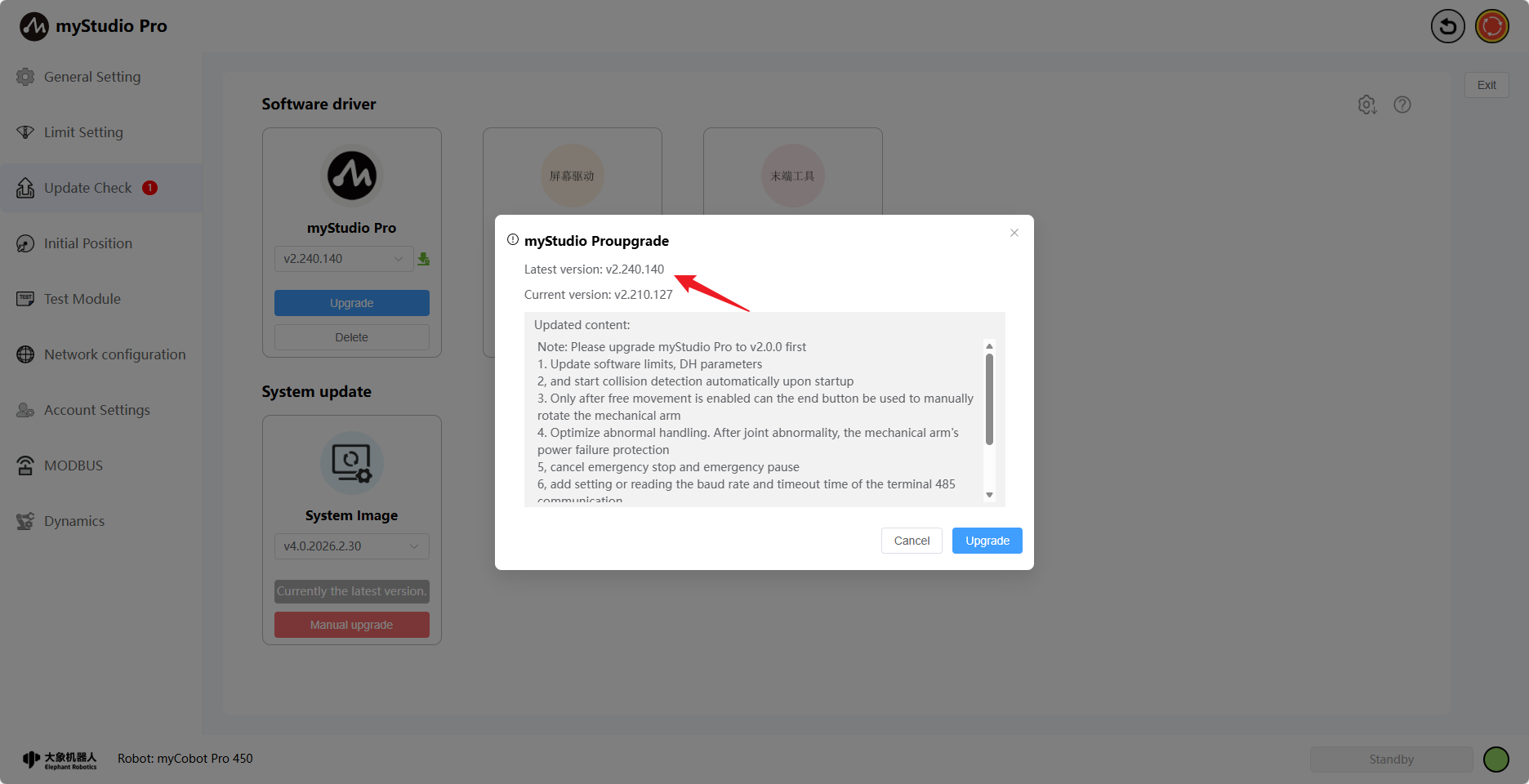
Clicking the Upgrade button will bring up the update details, the current version of the robotic arm, and the latest version.
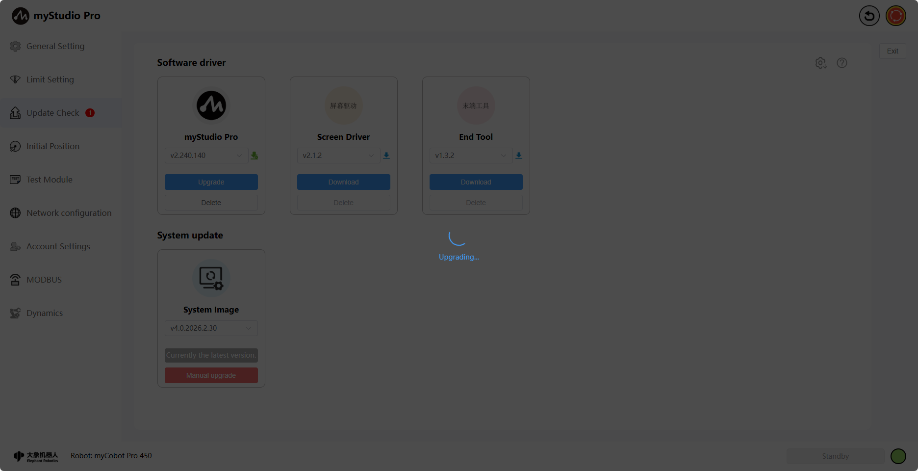
Clicking the Confirm button in the pop-up window will begin the screen driver upgrade. Simultaneously, the page will display an upgrade loading screen. Once the upgrade is complete, the loading screen will disappear, and a corresponding message will be displayed.
When the robotic arm has been upgraded to the latest version, the text "Currently the latest version" will be displayed.
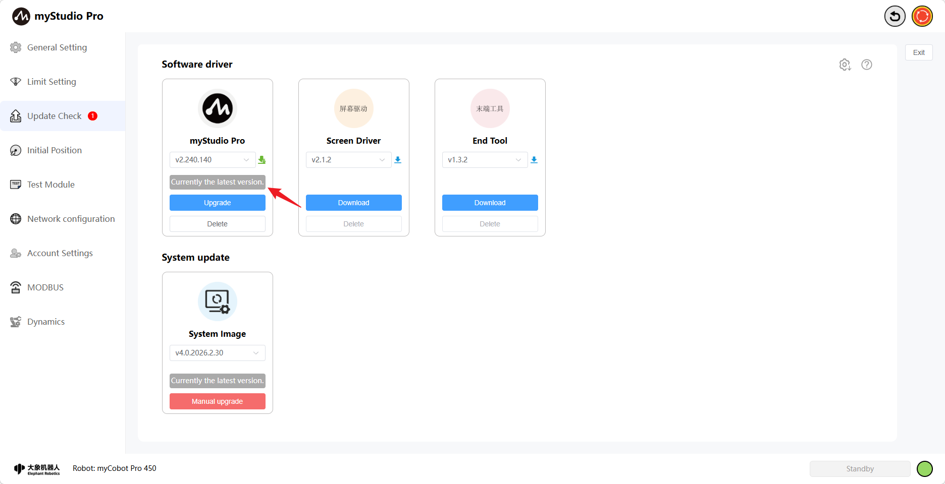
The myStudio Pro upgrade is now complete.
Screen Driver Firmware Upgrade
Function Introduction:
Screen Driver
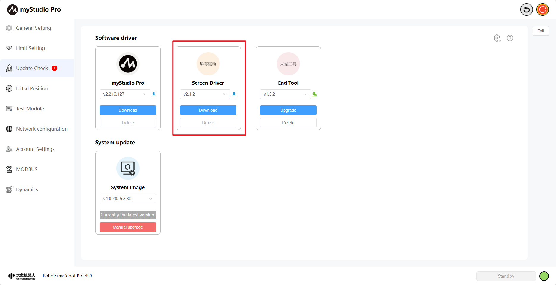
Version Number
The default is the current version. You can also select another version to download and upgrade. When the selected version is downloading, the icon next to the version number will be blue, and the delete button will be disabled.
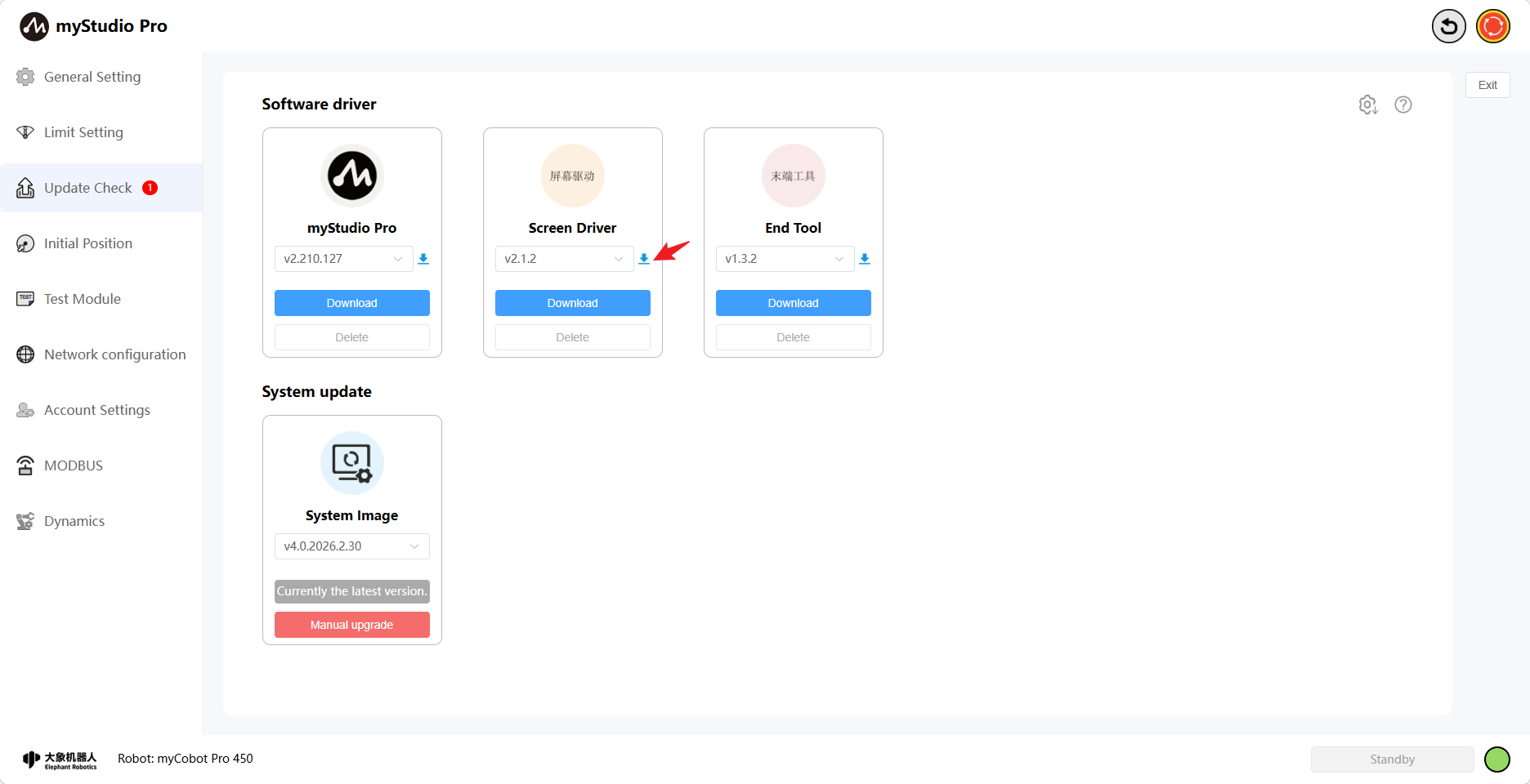
Clicking the download button will start the download of the selected version. Version selection is disabled at this time, and the download progress will be displayed when it begins.
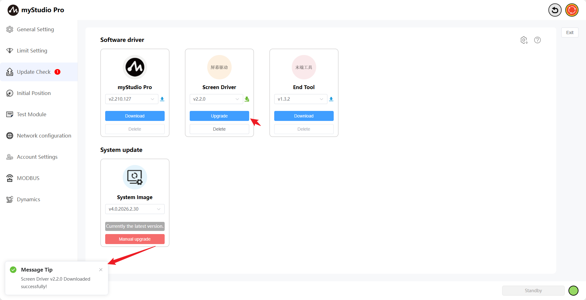
When the download is complete, the icon will turn green, the download progress bar will disappear, the upgrade button will be displayed, and the delete button will become available ...
When downloading Failed, a failure pop-up will appear and the icon will turn red. Clicking the [Re-download] button will re-download all previously failed drivers.
Clicking the [Delete] button will bring up a confirmation window. Clicking [Confirm] will delete the downloaded drivers.

Clicking the Upgrade button will bring up the update details, the current version of the robotic arm, and the latest version.
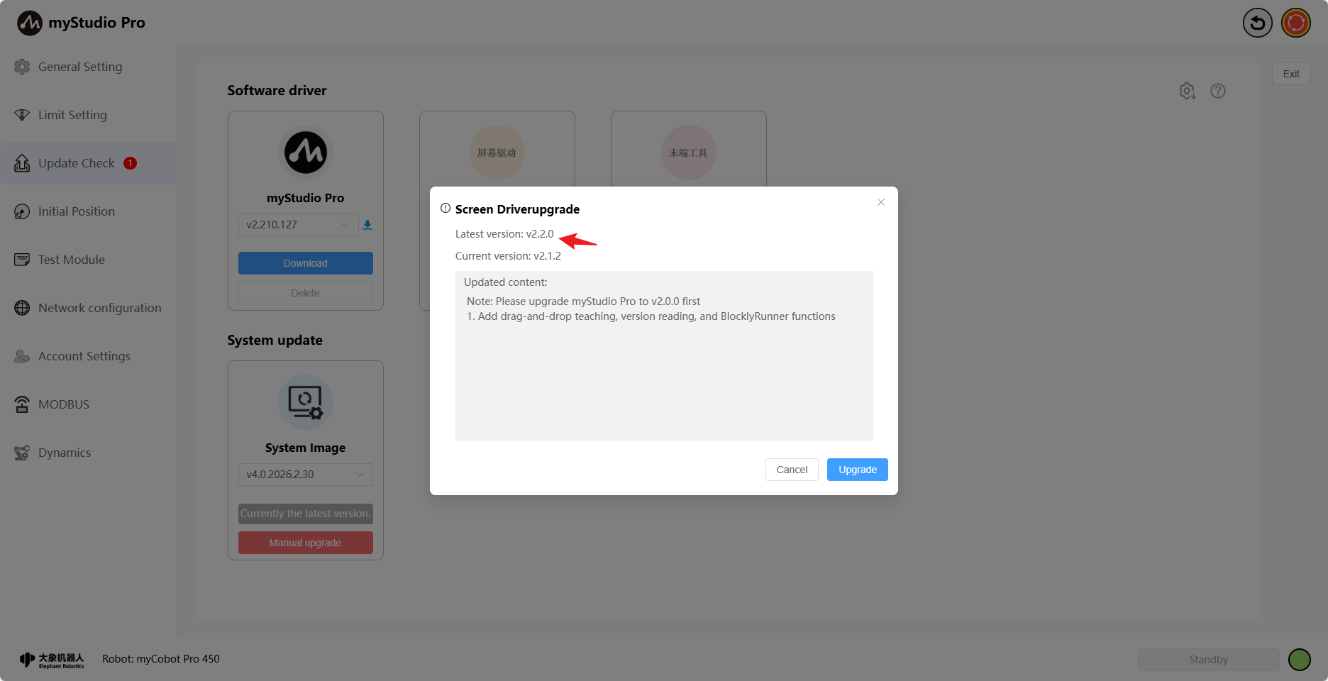
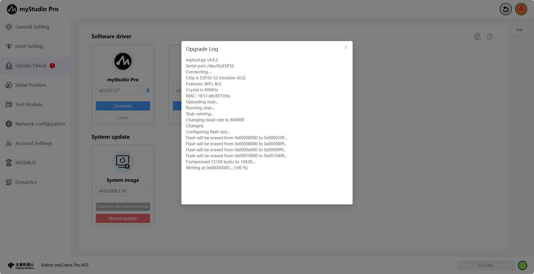
Clicking the Confirm button in the pop-up window will begin the screen driver upgrade. During this time, the robotic arm screen will go black, and the page will display the upgrade log in real time. A corresponding message will be displayed upon completion of the upgrade.
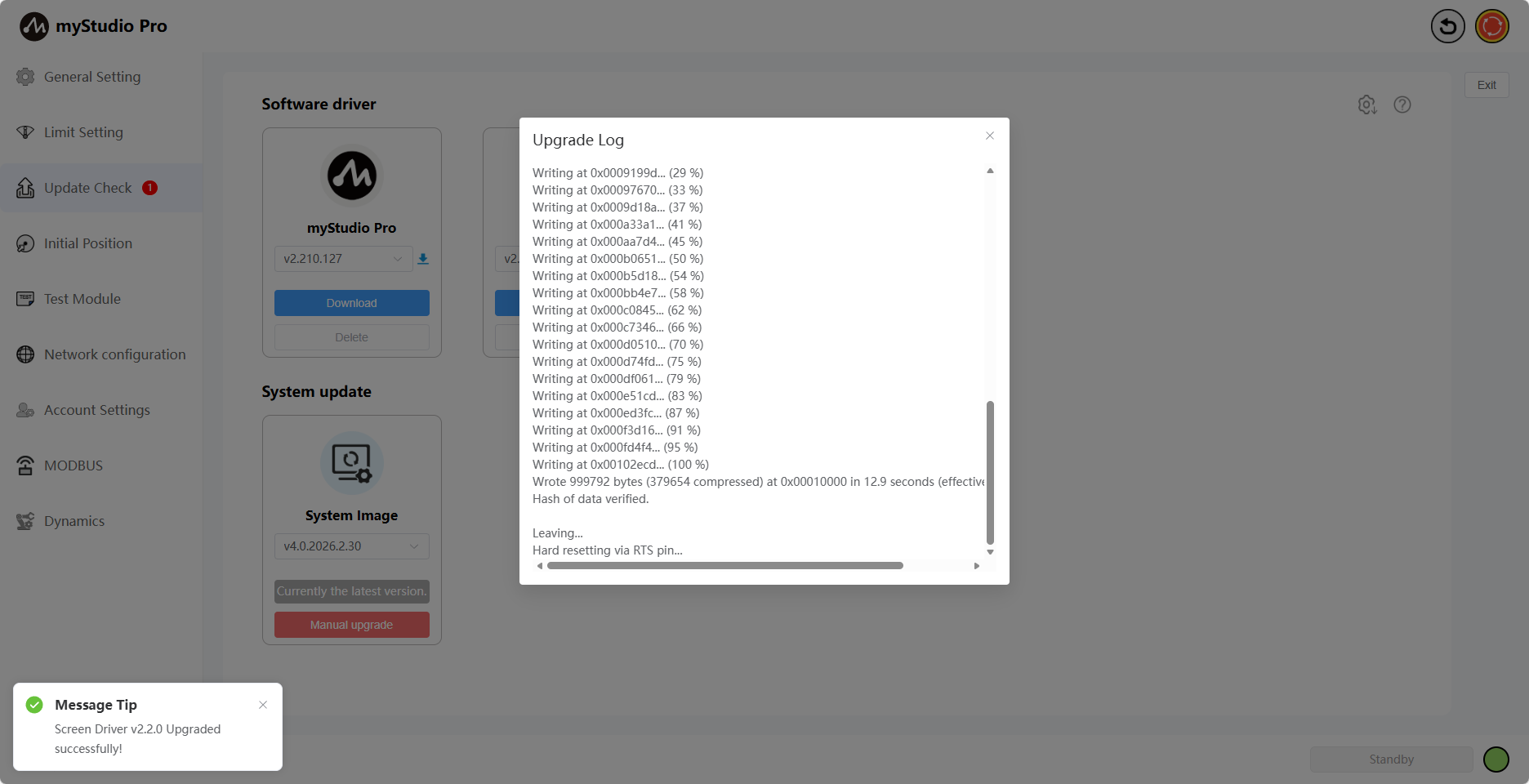
When the robotic arm has been upgraded to the latest version, the text "Currently the latest version" will be displayed.
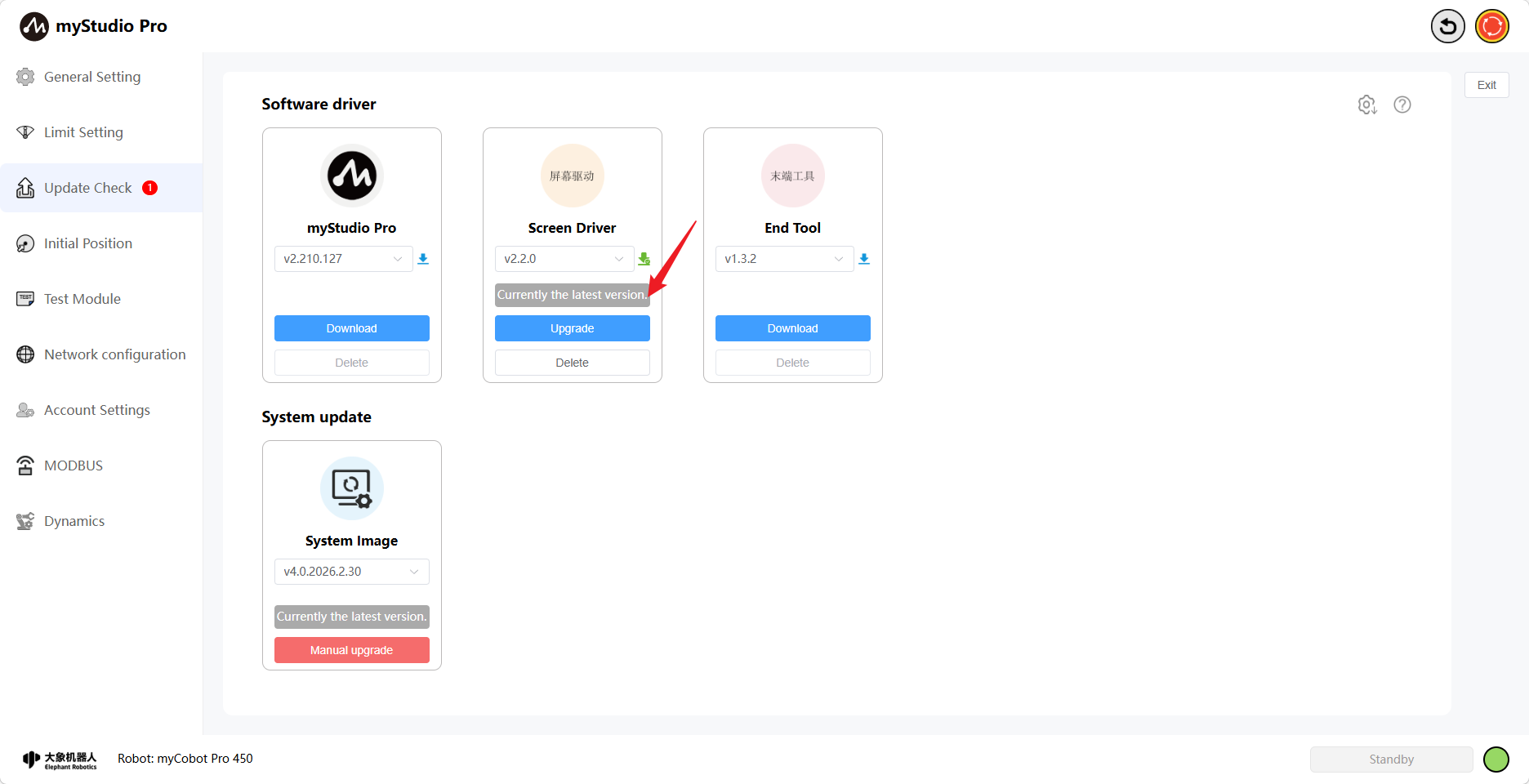
The screen driver upgrade operation is now complete.
End-effector Firmware Upgrade
Function Introduction:
End-effector
Version Number
The default is the current version. You can also select another version to download and upgrade. When the selected version is downloading, the icon next to the version number will be blue, and the "Delete" button will be disabled.

Clicking the "Download" button will download the selected version. Version selection is disabled at this time. The download progress will be displayed when it starts.
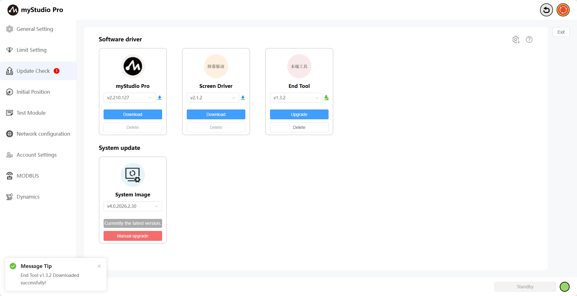
When the download is complete, the icon turns green, the download progress bar disappears, the "Upgrade" button appears, and the "Delete" button becomes available.
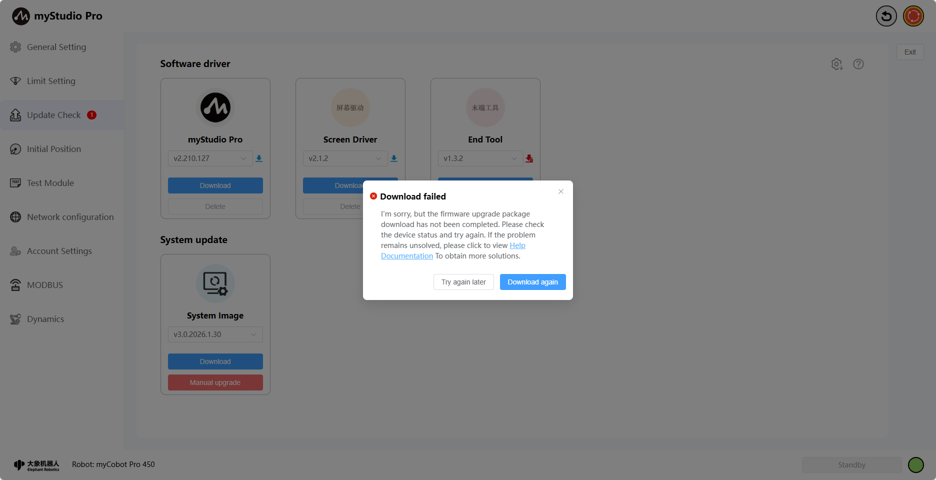
If the download fails, a failure pop-up will appear, and the icon will turn red. Clicking the "Re-download" button will re-download all previously failed drivers.
Clicking the "Delete" button will bring up a confirmation window. Clicking "Confirm" will delete the downloaded drivers.


Clicking the Upgrade button will bring up the update details, the current version of the robotic arm, and the latest version.
Clicking the Confirm button in the pop-up window will begin the screen driver upgrade. Simultaneously, the page will display an upgrade loading screen. Once the upgrade is complete, the loading screen will disappear, and a corresponding message will appear.

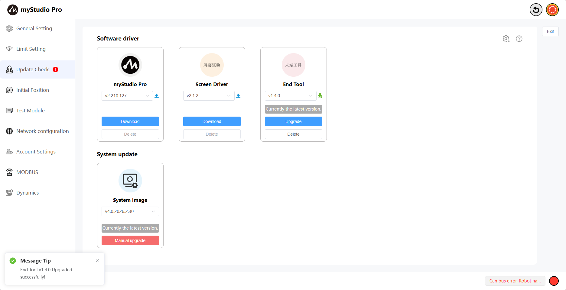
When the robotic arm has been upgraded to the latest version, the text "Currently the latest version" will be displayed.
The end effector upgrade is now complete.
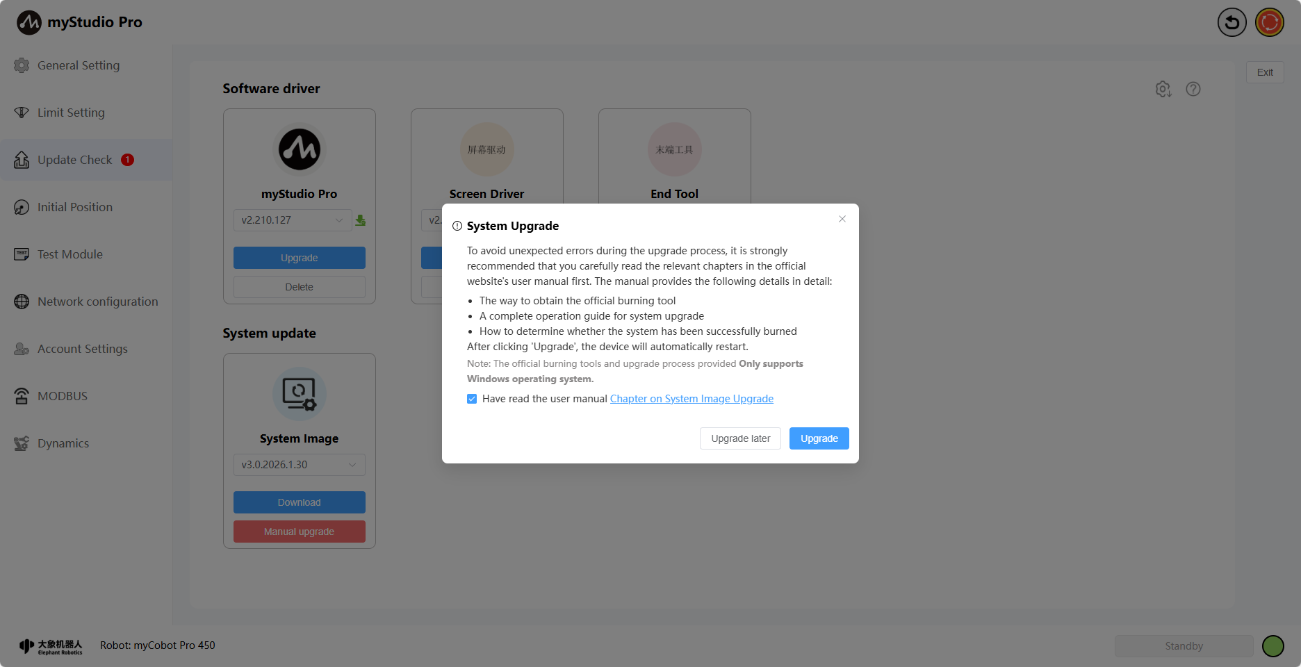
In addition, this page also provides system image download and manual upgrade buttons.
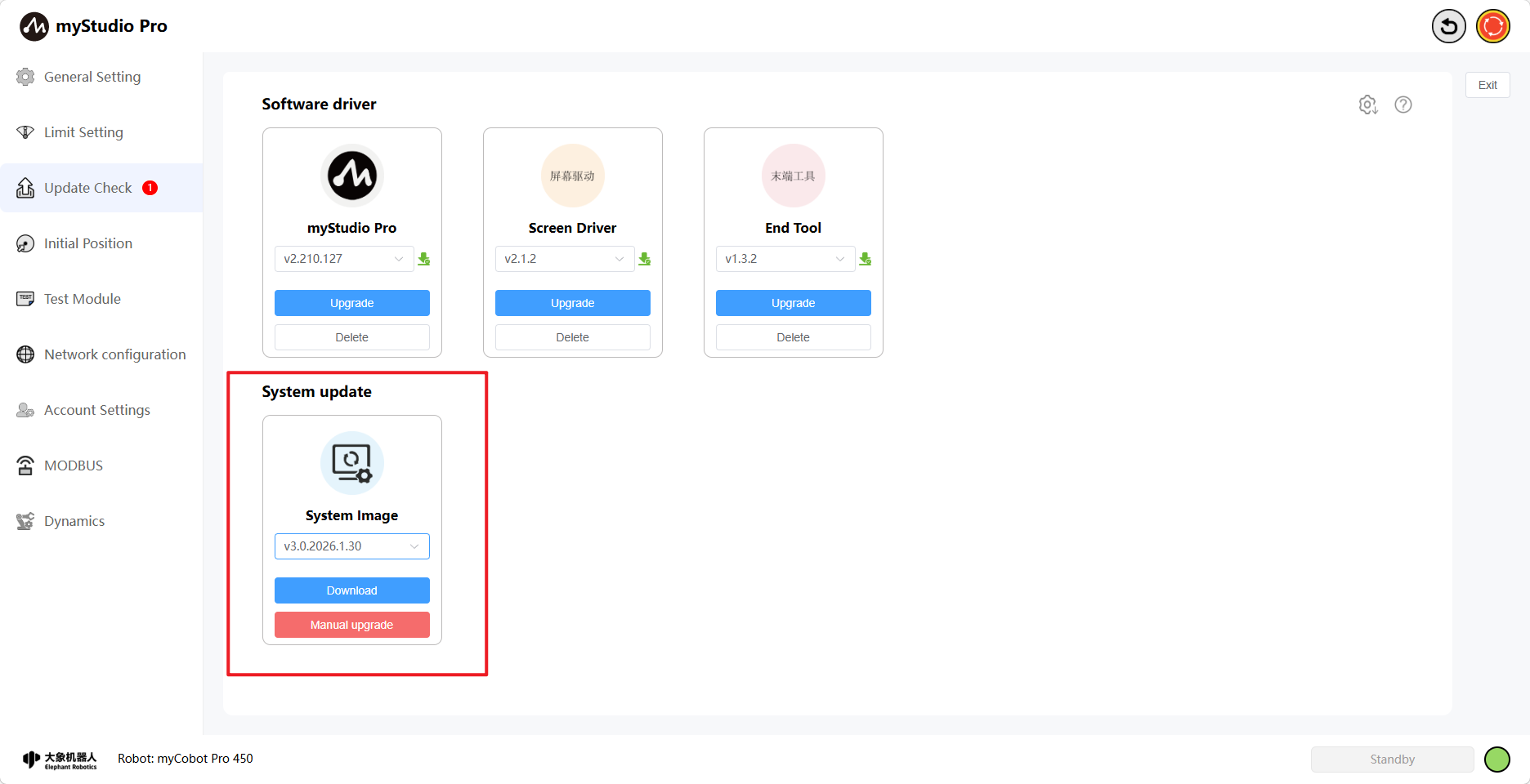
Clicking the Download button will download the selected image version to your local machine. The downloaded file contains...
Image, burning tool, instructions.
Clicking the Manual Upgrade button will bring up a pop-up window. See the pop-up window for details. Clicking the <System Image Upgrade Section> will redirect you to the page where you can view the specific upgrade steps.
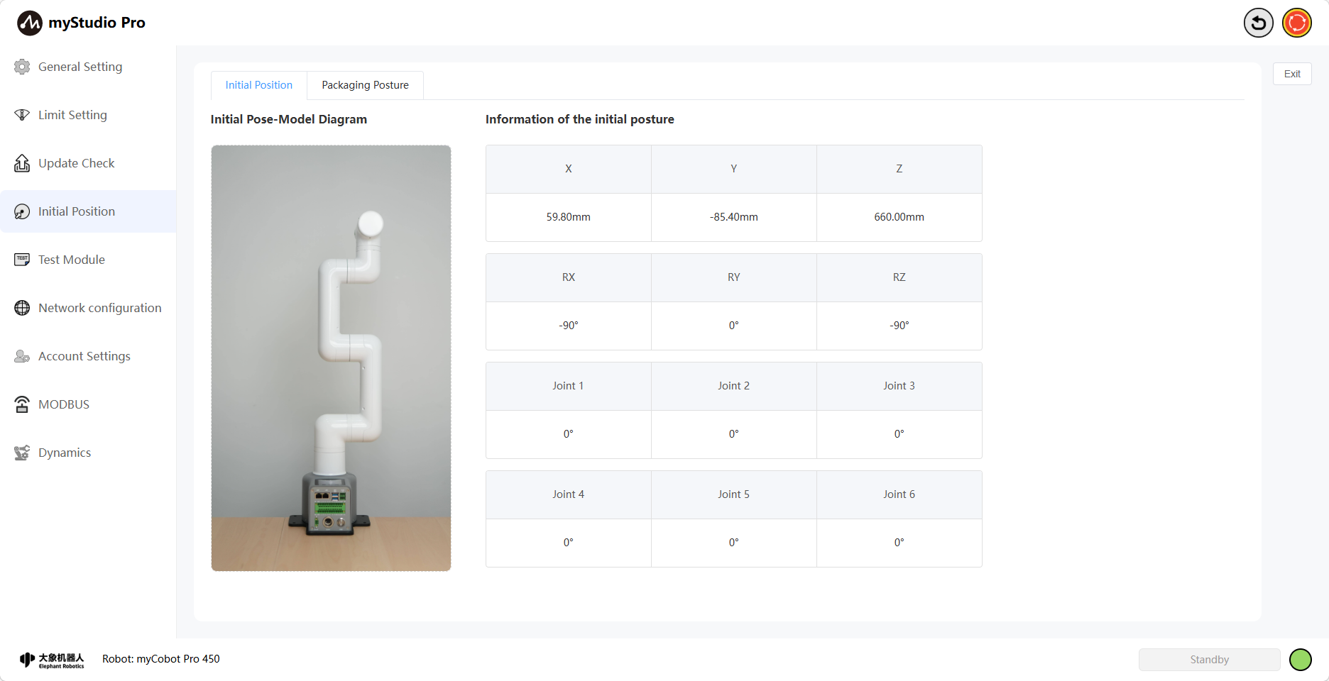
5 Initial Position
Clicking the Initial Position icon will take you to the Initial Position page. This page contains Initial Position and Initial Position content. You can switch between the content you want to access using the toggle button.
Initial Attitude Page: Displays the robot arm's initial attitude model, joint angle information, and coordinate attitude information.
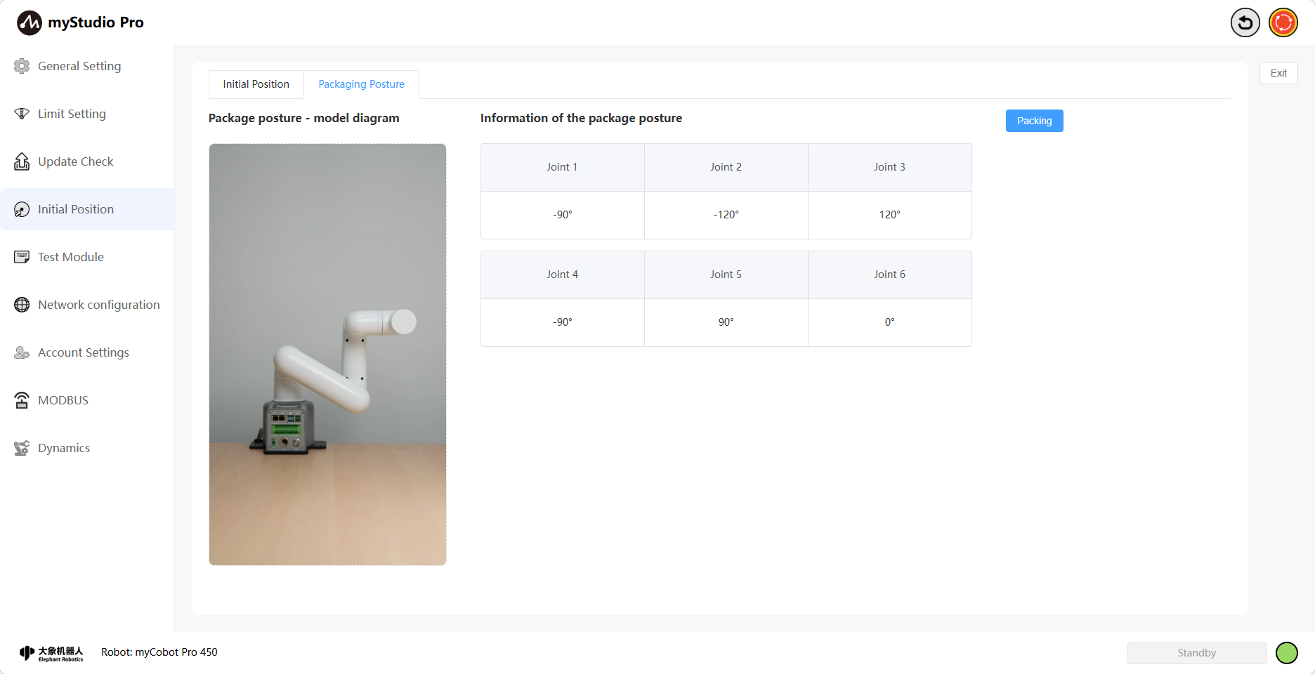
Packaging Attitude Page: Displays the robot arm's packaging attitude model, joint angle information, and a packaging button. This button is a function button; clicking it will move the robot arm to the packaging attitude.
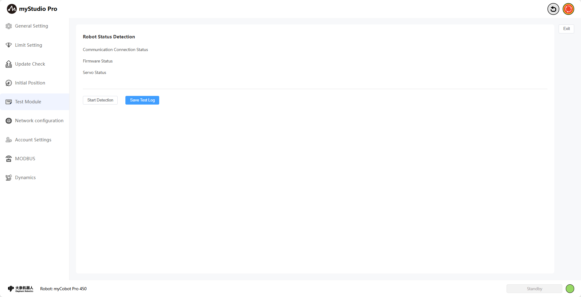
6 Test Module
Clicking the Test Module icon button will take you to the test page.
The Test page primarily tests the robot arm's communication connection, firmware version, servo motor status, etc.
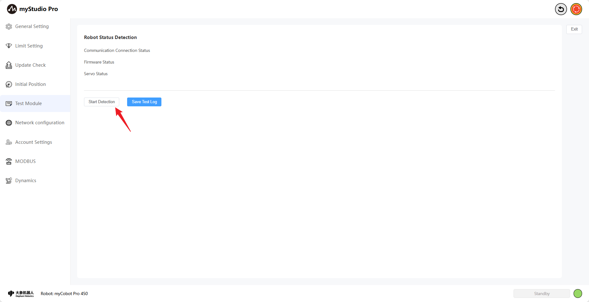
Click the Start Test button to begin the test.
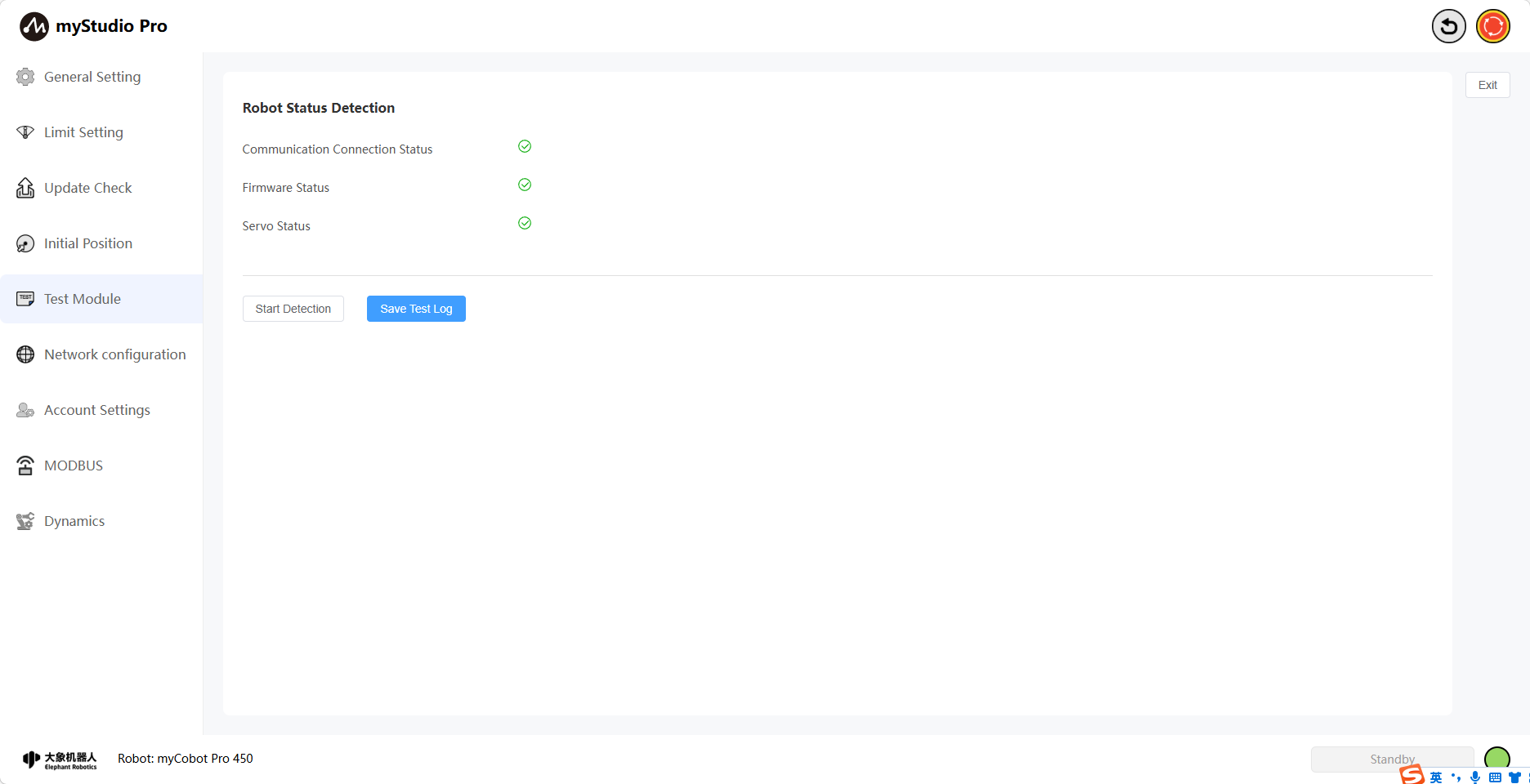
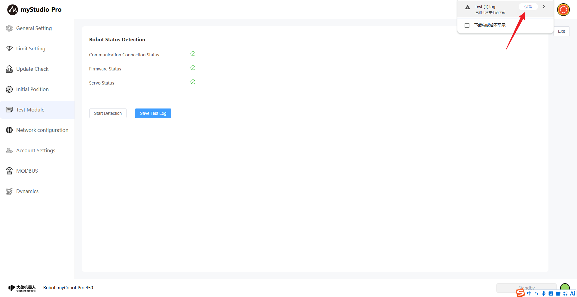
After the test is complete, click the Save Test Log button. The result for each test item will be displayed, indicating whether it passed or failed. Green indicates success, and black indicates failure. You can save the test results to a local log file for further review.
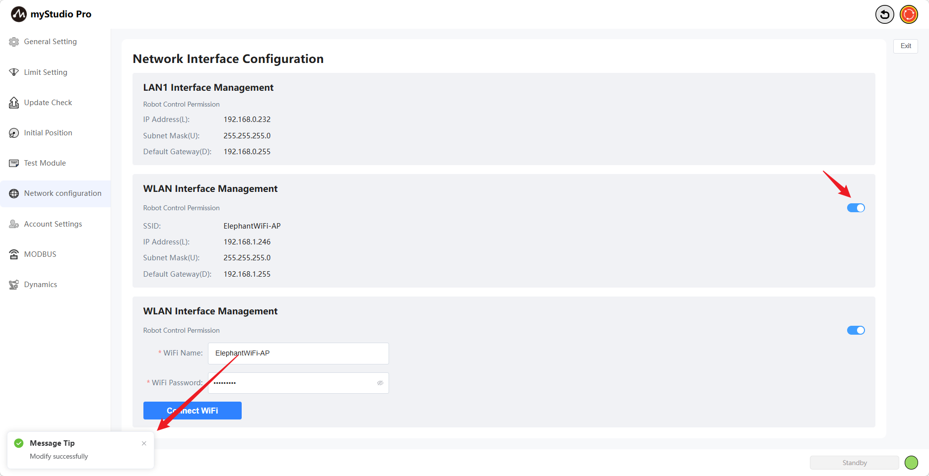
7 Network Configuration
Clicking the Network Configuration icon will take you to the network configuration page. This page mainly displays the robotic arm's network port information, including LAN1, LAN2, and WLAN.
Note: The page content is displayed in real time; network port information is only displayed when a network port is in use.
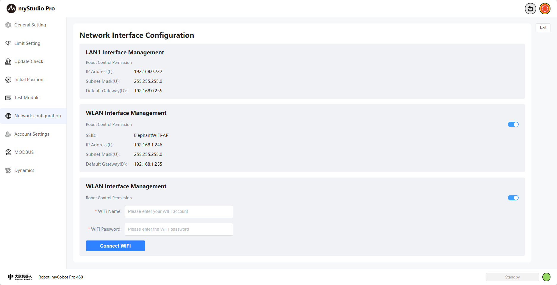
Simultaneously, you can connect to WiFi on this page. Enter the WiFi username and password you want to connect to and click the Connect WiFi button to connect.

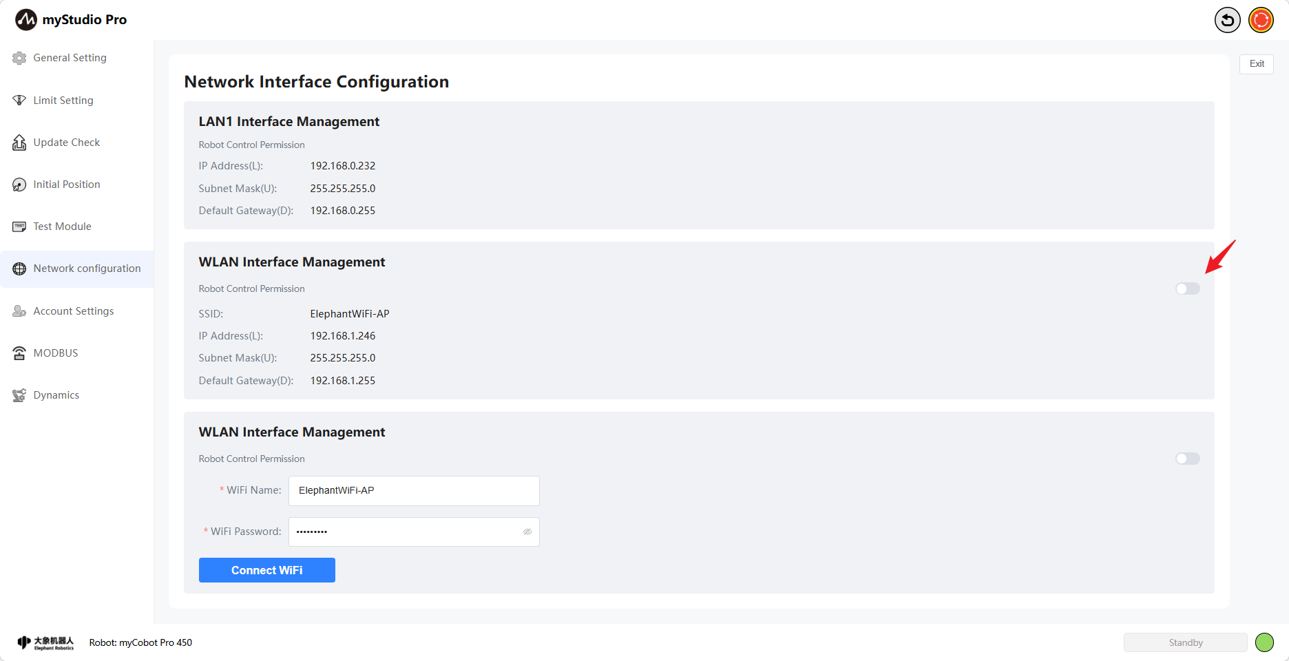
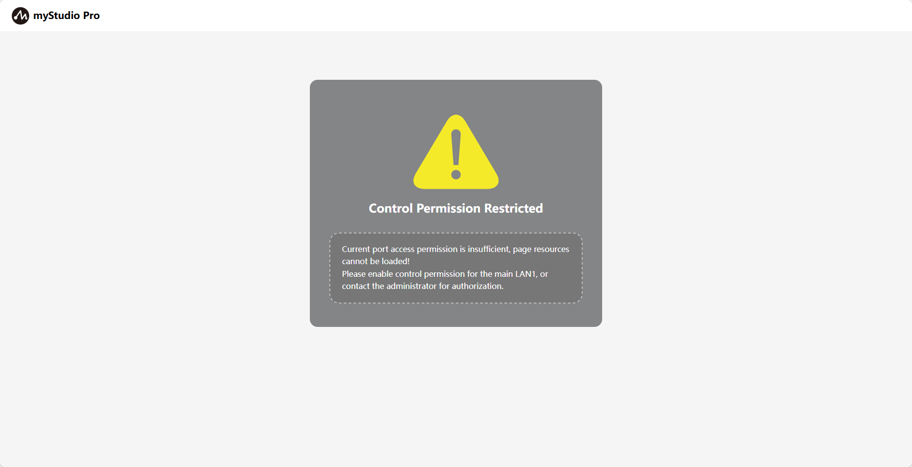
Furthermore, you can modify the robot control permissions for this network port on this page. When robot control permissions are not enabled, accessing myStudio Pro will display a message indicating no control permissions. myStudio Pro can only be used normally when control permissions are enabled.
The following explanation is based on the WLAN network port. The control logic for the LAN2 network port is similar.
In your browser, enter the IP address of your WLAN port to access myStudio Pro (Wi-Fi connected & control permissions not enabled).
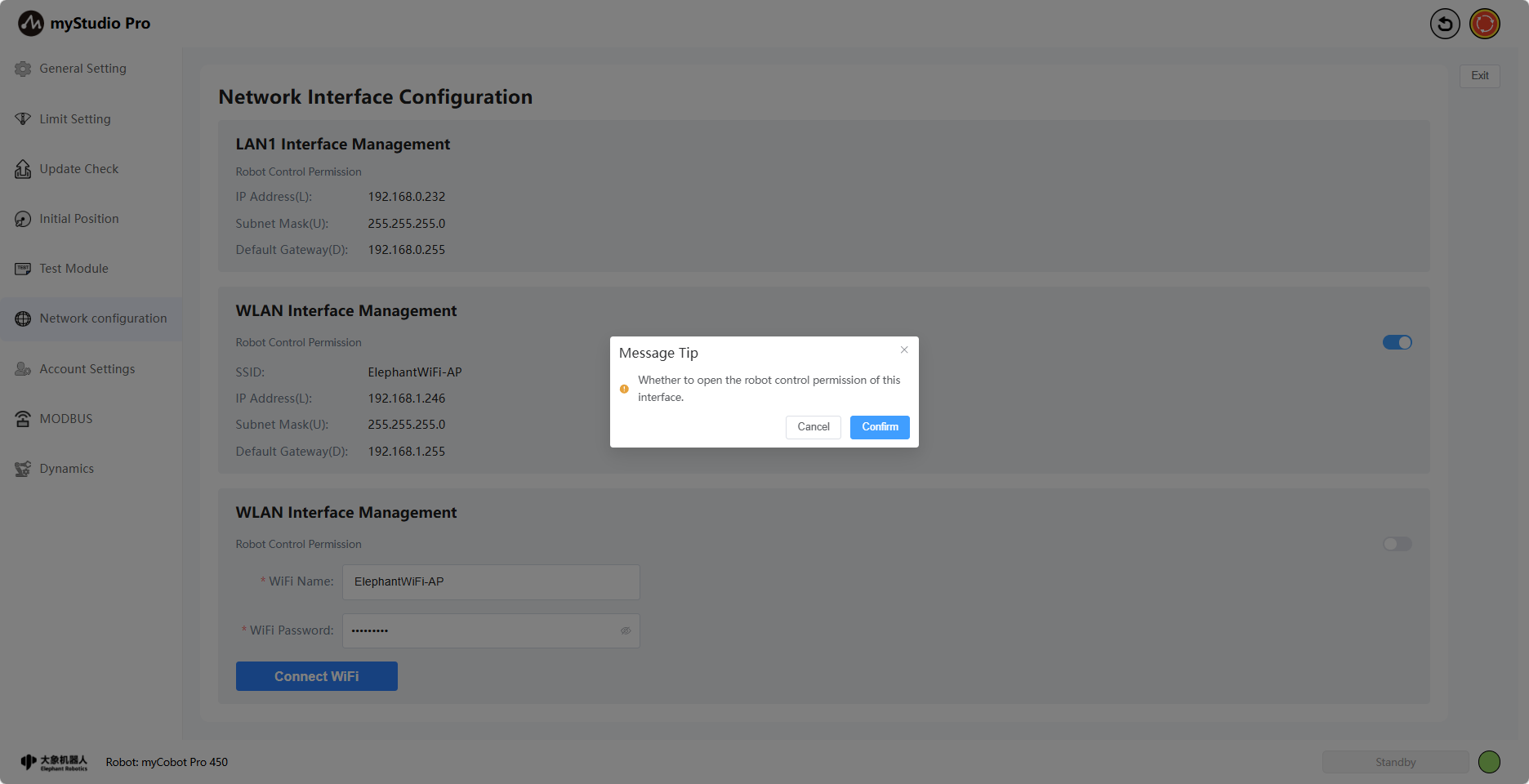
When enabling/disabling control permissions, a second confirmation is required. Click "Confirm" to successfully enable/disable control permissions.
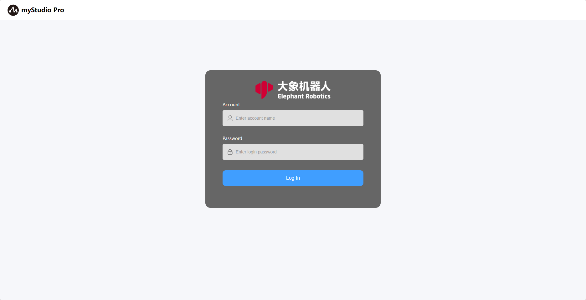
In your browser, enter the IP address of your WLAN port to access myStudio Pro (Wi-Fi connected & control permissions enabled). You will be taken to the account login page. Enter the correct username and password to use myStudio Pro. The default username and password are admin and 123. If you have changed your username and password (see point 8 for instructions), please use the changed username and password to log in; otherwise, you will not be able to use myStudio Pro.
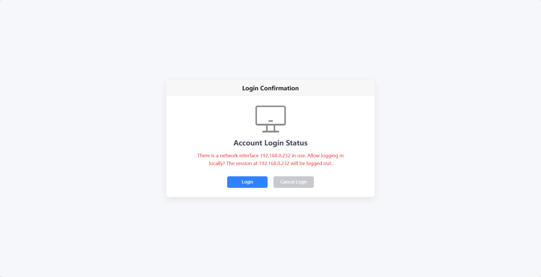
After successful login, the system will first check if any network port is currently using myStudio Pro. If so, a second login confirmation will be required. Clicking "Confirm" will automatically log the currently used network port offline, allowing you to use myStudio Pro normally. Clicking "Cancel" will return you to the login page. Otherwise, you will directly enter the myStudio Pro main interface.
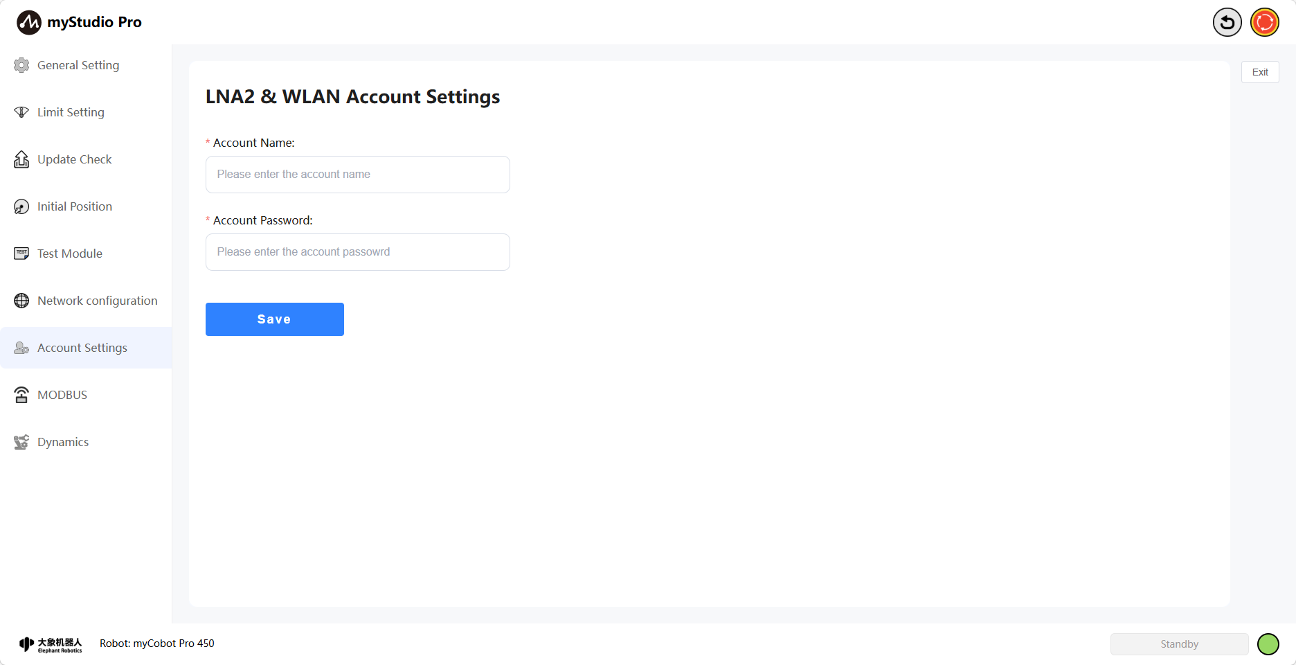
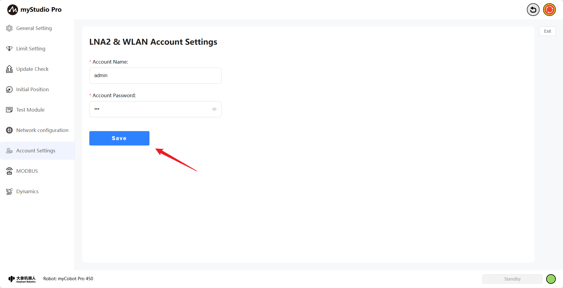
8 Account Settings
Clicking the Account Settings icon button will take you to the account settings page. This page is mainly used to set the username and password when logging into myStudio Pro using LAN2 or WLAN network ports. Once your username and password are successfully saved, you will use them to log in to myStudio Pro the next time. Otherwise, you will not be able to use myStudio Pro normally.
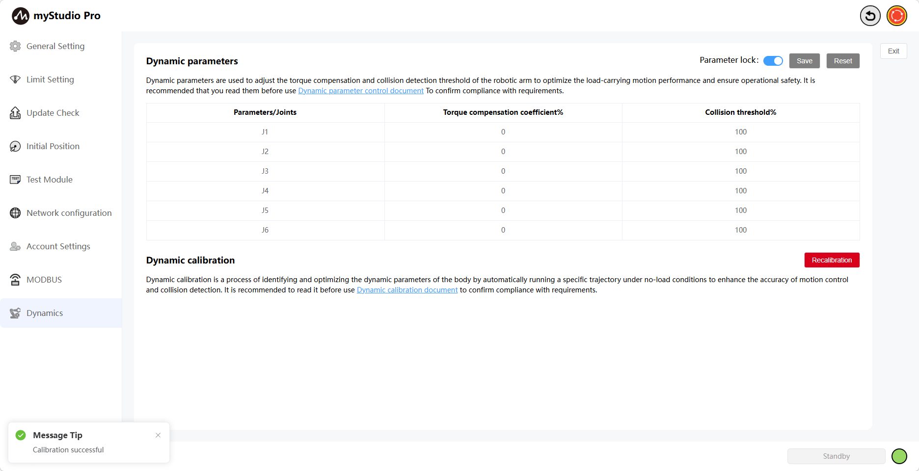
9 Dynamics
Clicking the Dynamics icon will take you to the Dynamics page. This page is mainly used to set dynamic parameters, including torque compensation coefficients and collision threshold parameters. It also allows for trajectory preview and calibration, enabling optimization of body dynamic parameters to improve motion control accuracy and collision detection accuracy.
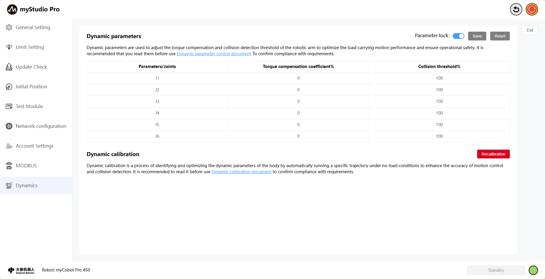
9.1 Dynamics Parameters
The Parameter Lock button is locked by default, and its color is blue. The Save and Reset buttons are grayed out and disabled, indicating that dynamics parameters cannot be modified.
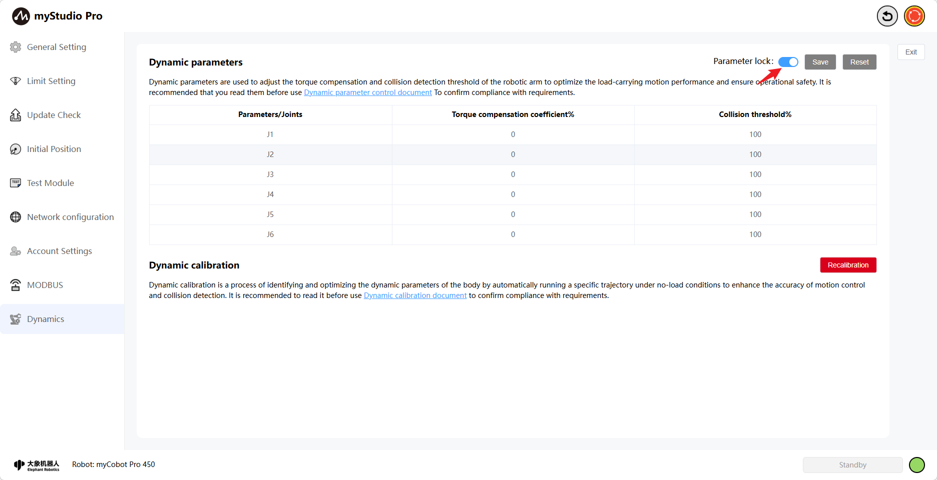
When the parameter is locked, clicking the Parameter Lock button will turn it gray, indicating that the button is unlocked and dynamics parameters can be modified. The Save and Reset buttons will then be available again.
Torque Compensation Coefficient Default Value 0% (0-50%): Sets the friction compensation system of the torque loop. A larger coefficient makes it easier to drag. The default collision threshold is 100% (range 50-250%). This sets the collision threshold for the joints; a smaller value makes collisions more likely.
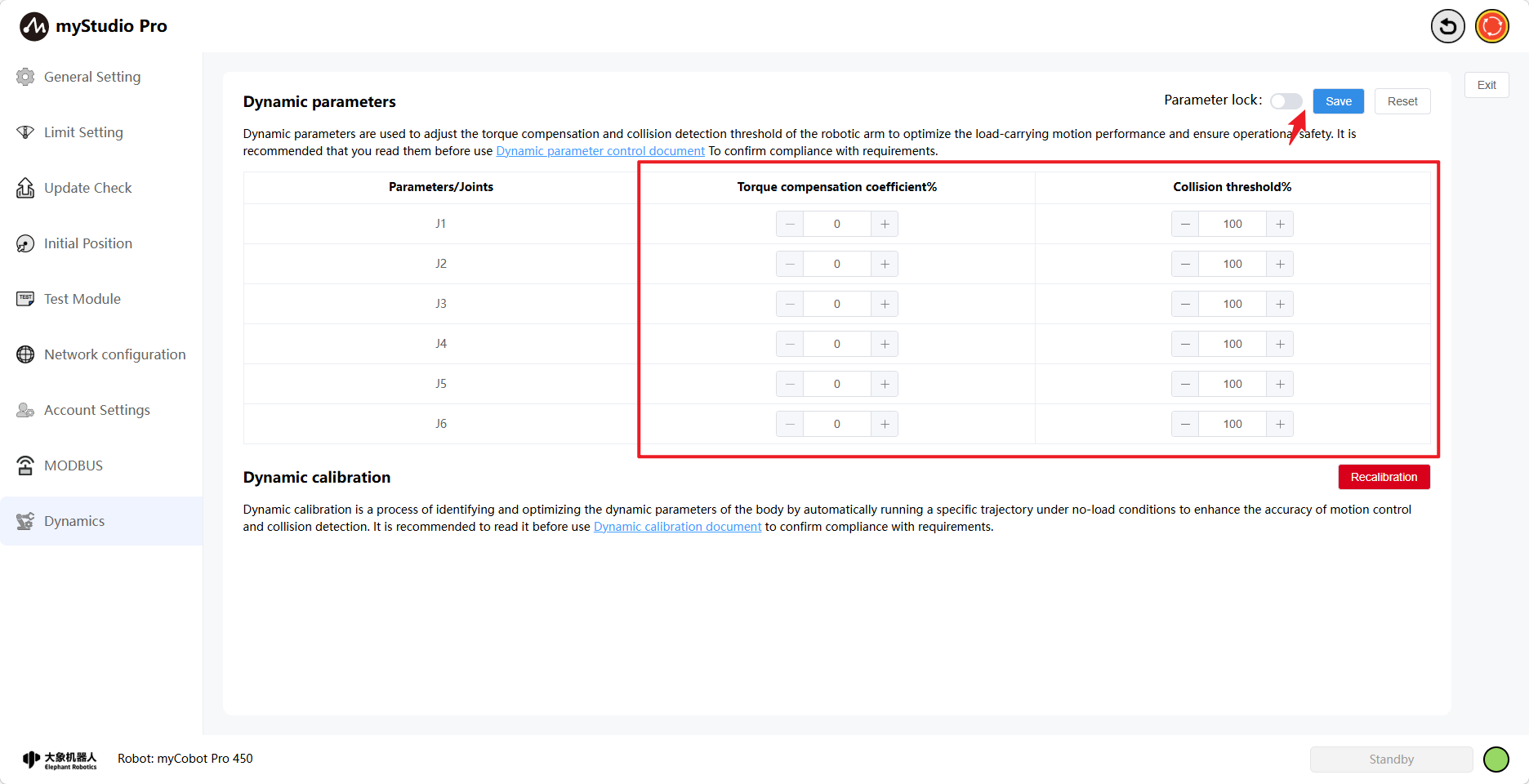
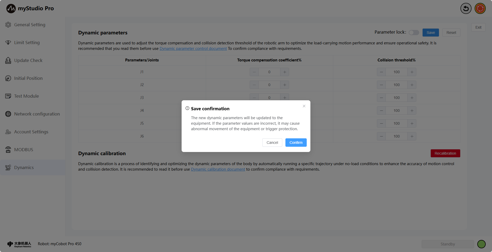
Clicking the Save button will save the modified torque compensation coefficient and collision threshold. A message will appear on the page upon successful setting, and the parameters will be automatically locked.

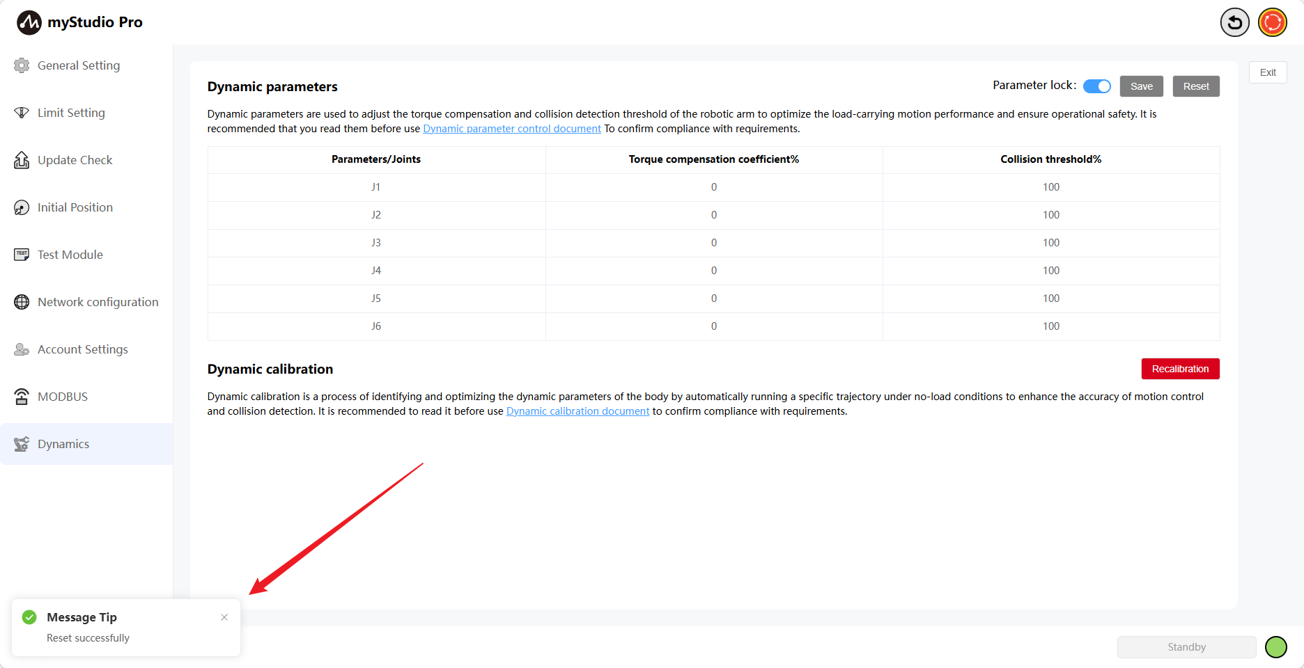
Click the Reset button to restore all torque compensation coefficients and collision thresholds to their default settings. A prompt will appear asking if you want to restore the default settings.
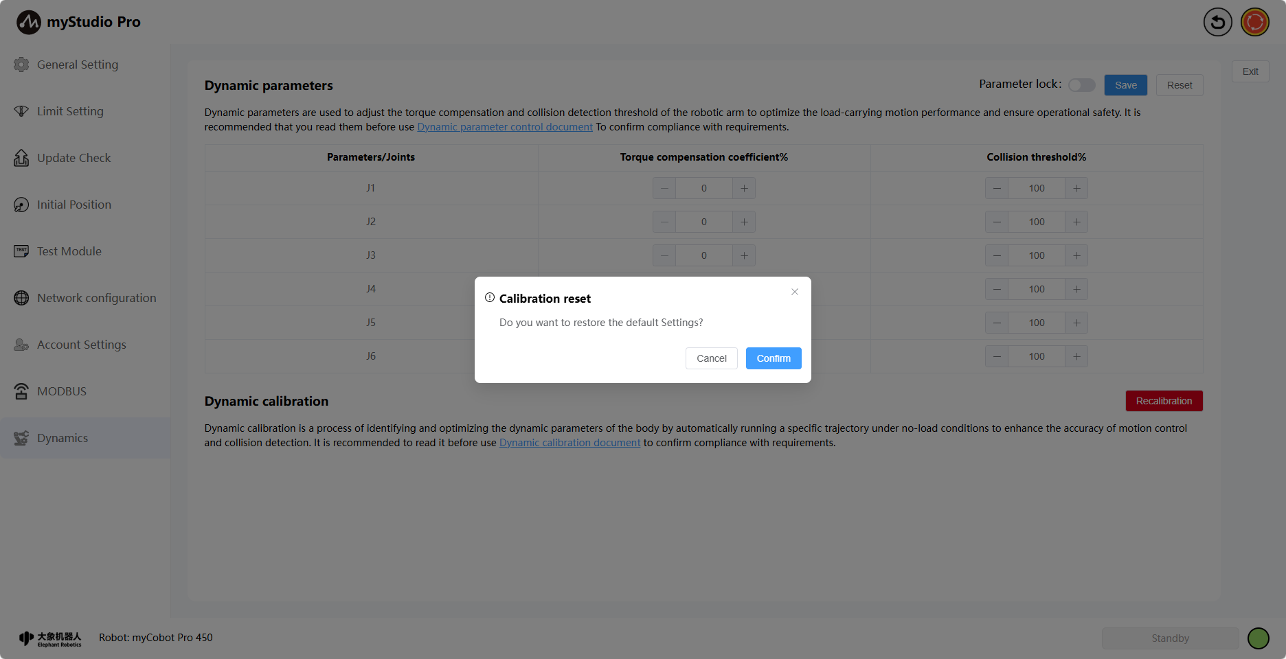
Clicking OK will display a message indicating whether the setting was successful.
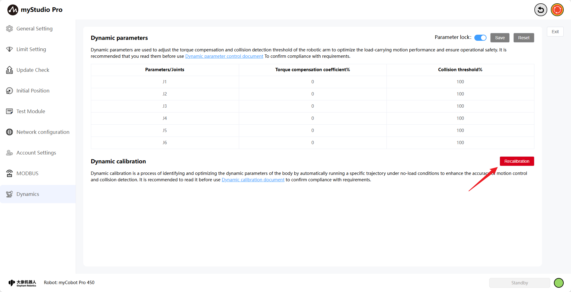
9.2 Dynamics Calibration
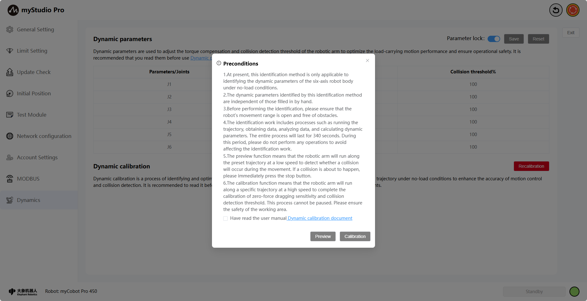
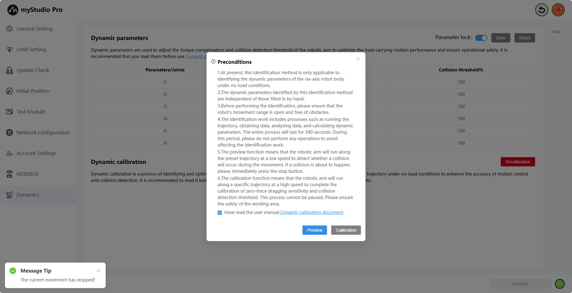
Click the Recalibrate button
This will open the Prerequisites modal window, which displays the prerequisites for calibration. Please carefully read the prerequisites before proceeding with the preview or calibration operation. Ensure the prerequisites are met.
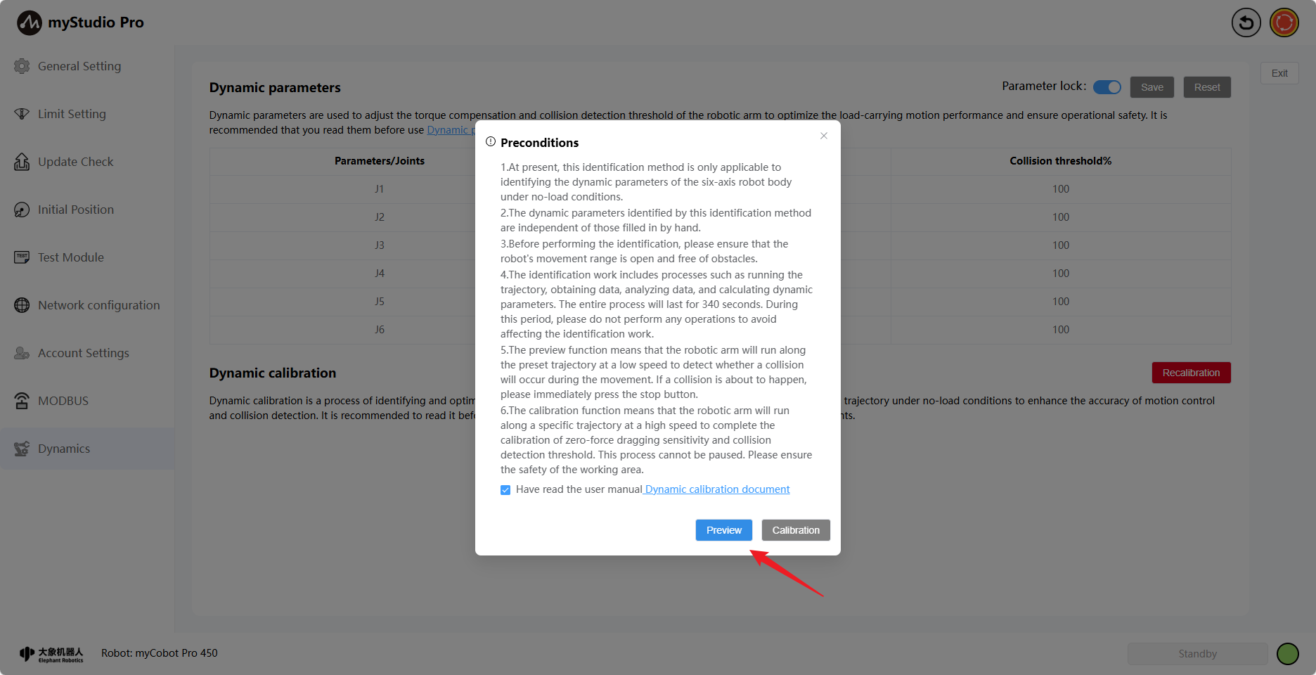
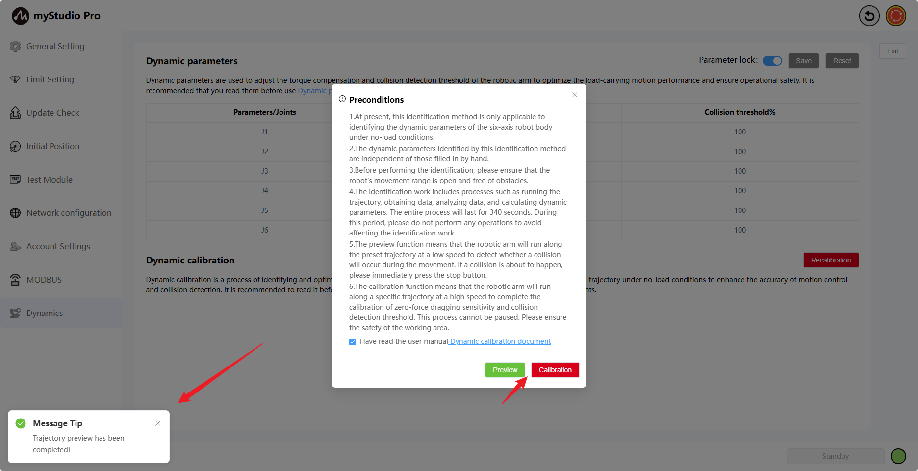
The Preview and Calibrate buttons are disabled by default. The Preview button will only become available (blue) when you have finished reading and checked the checkbox.
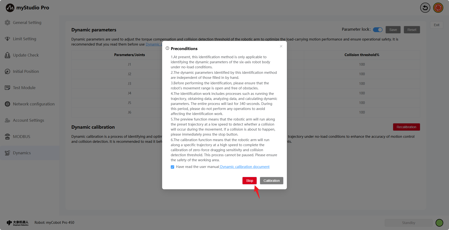
Clicking the button will preview the robotic arm's trajectory. During the preview, you can stop it; clicking the red Stop button will display a stop confirmation window.
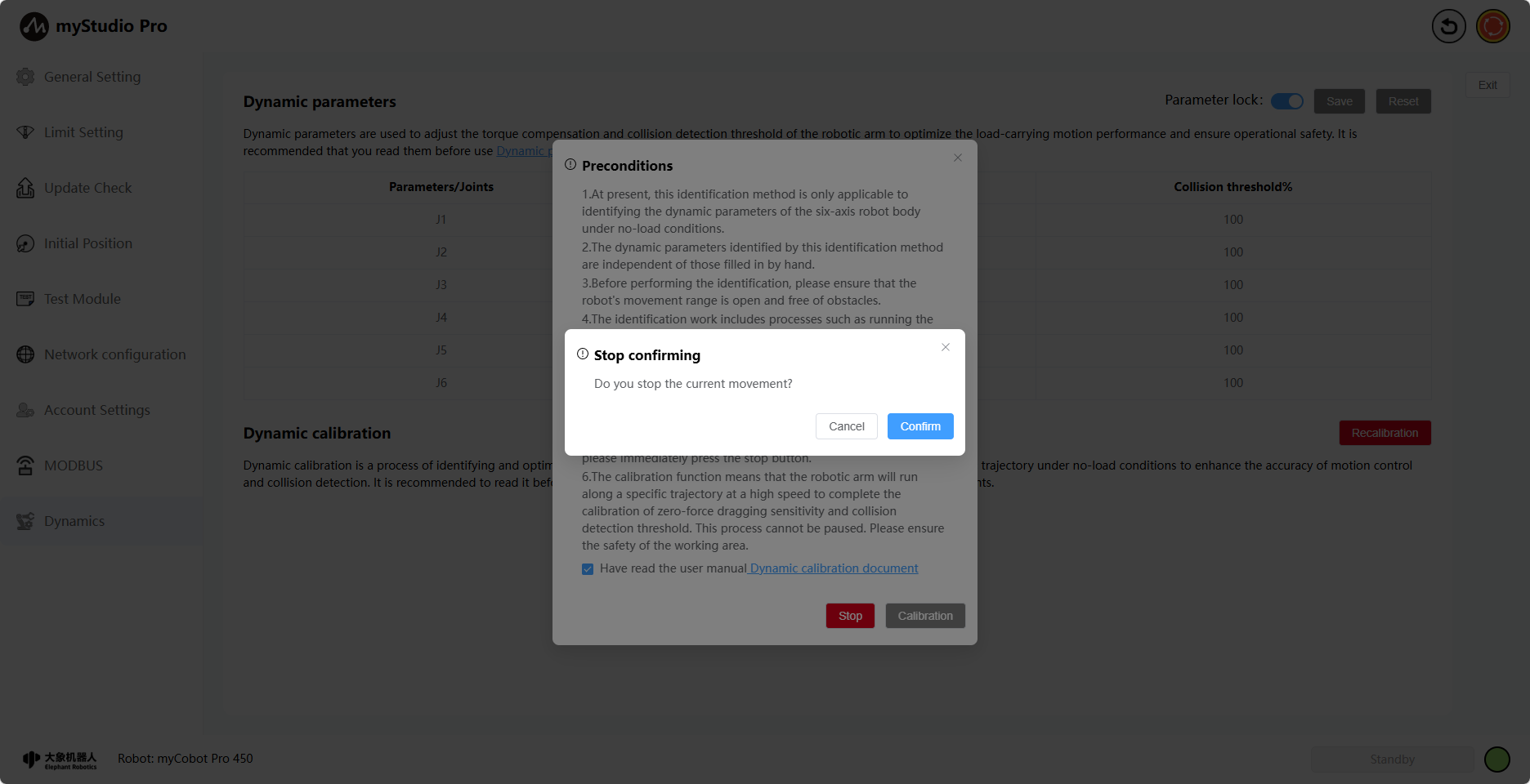
Click the Confirm button to stop the motion. A corresponding message will be displayed on the page upon successful stopping.
Once the preview is complete, the Stop button disappears, the Preview button turns green, and the Calibrate button becomes available.
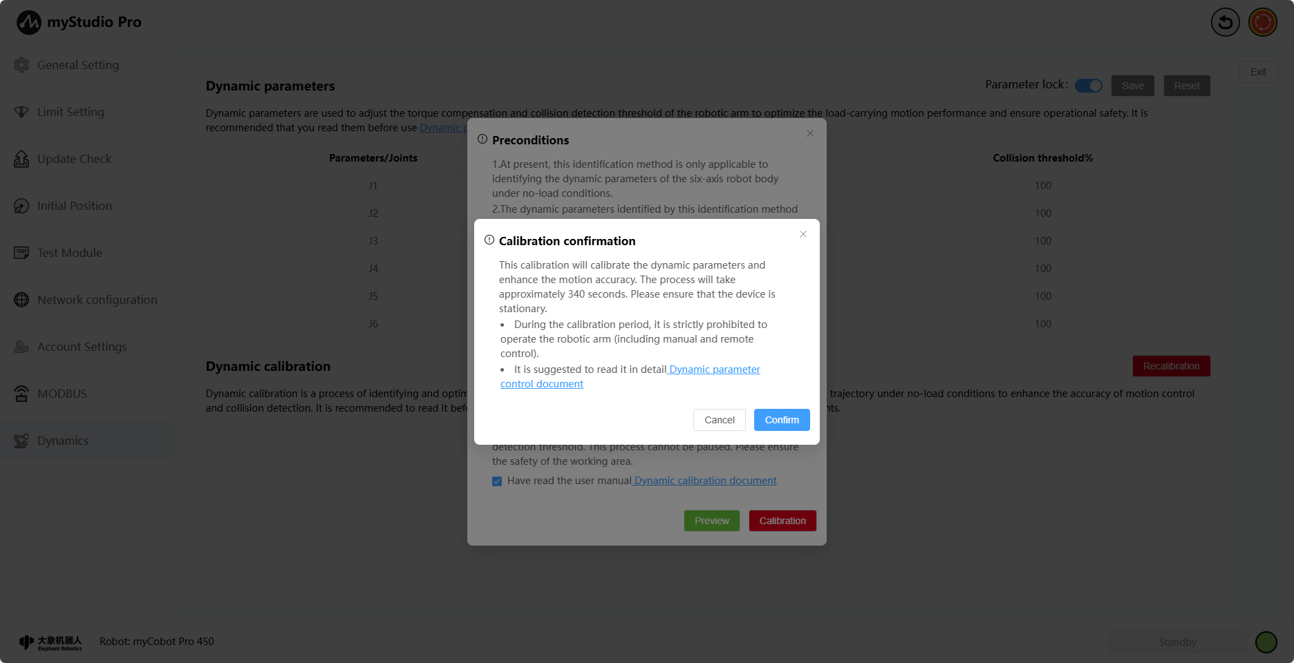
Clicking the Calibrate button will display a calibration confirmation pop-up. After clicking the Confirm button, the page will start a calibration countdown (340s) for the calibration operation. Please wait patiently during the calibration process.
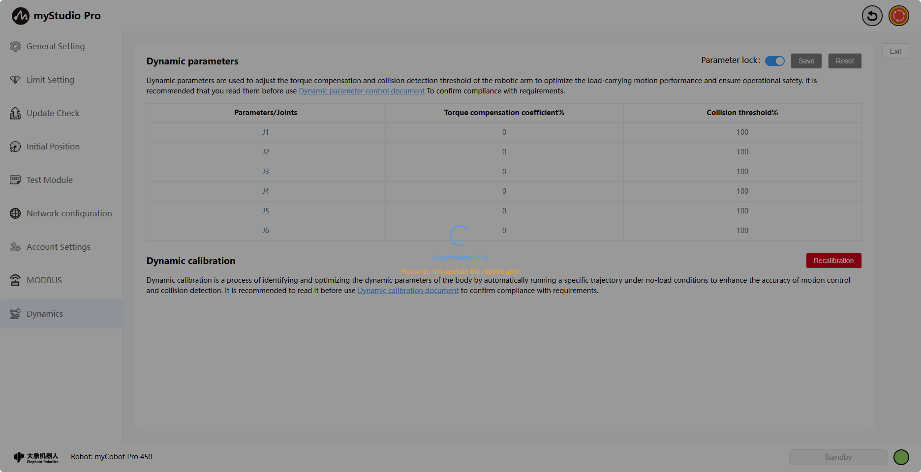
After successful calibration, a corresponding message will be displayed, indicating that the calibration process is complete.