Electrical characteristic parameter
1 Overview of electrical interfaces
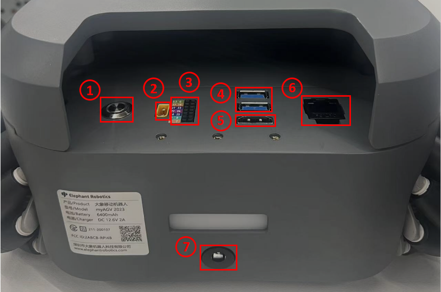
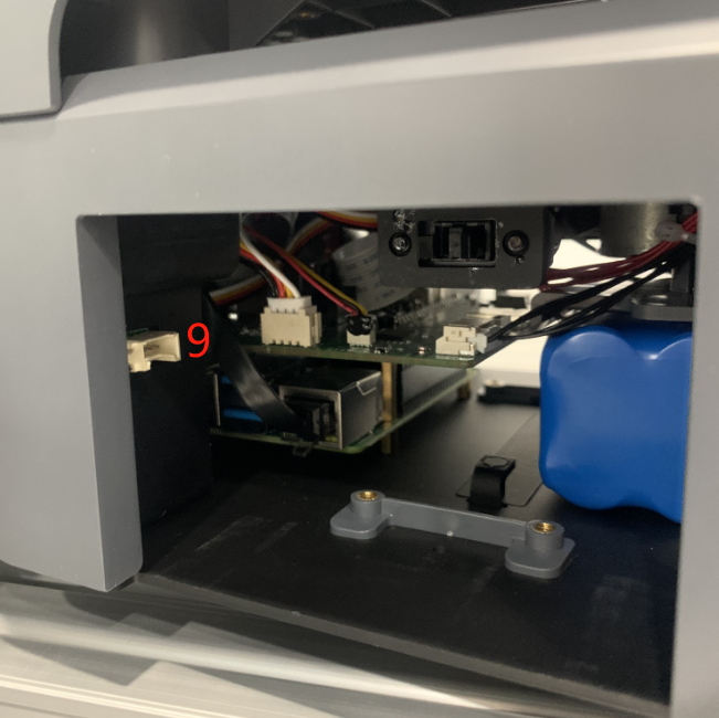
| Number | Interface | Definition | Function | Remark |
|---|---|---|---|---|
| 1 | Switch | control input power on and off | With lights (lights on) | |
| 2 | Power supply interface of robot arm | Supply power to my series robot arm (12V 5A) | ||
| 3 | DC/IO interface | 3.3 | DC3.3V | |
| 17 | GPIO 17 | |||
| 27 | GPIO 27 | |||
| 22 | GPIO 22 | |||
| 10 | GPIO 10 | |||
| 9 | GPIO 9 | |||
| 11 | GPIO 11 | |||
| G | GND | |||
| 10 | GPIO 10 | |||
| 23 | GPIO 23 | |||
| 24 | GPIO 24 | |||
| 25 | GPIO 25 | |||
| 8 | GPIO 8 | |||
| 7 | GPIO 7 | |||
| 4 | USB2.0 | USB2.0*2 | Can be connected to external devices or U disk shion | |
| 5 | HDMI | use to connect a screen | ||
| 6 | network port | Ethereum | Ethernet port communication | |
| 7 | Power DC Input interface | DC 12V | power input | |
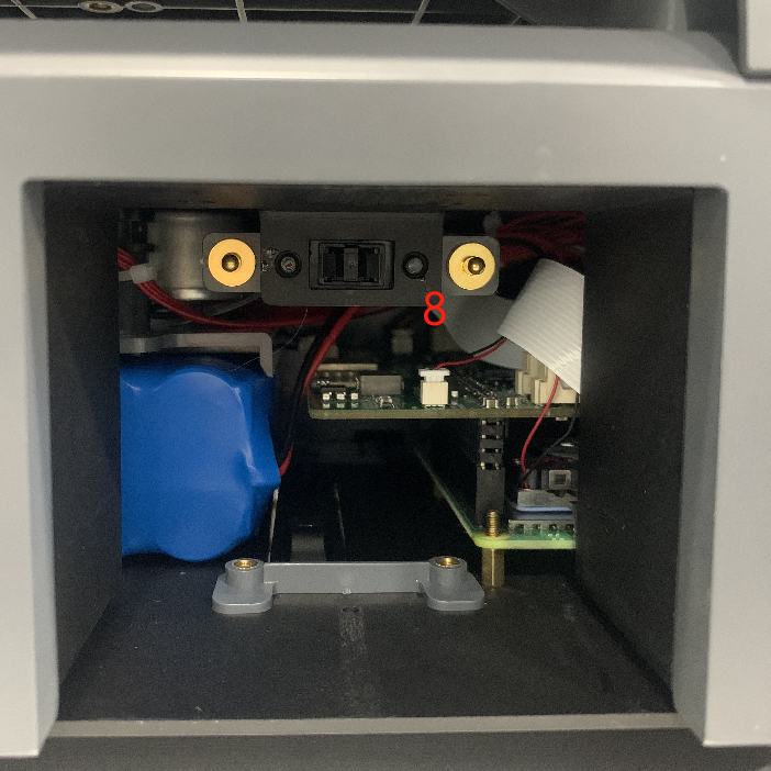
| 8 | Standby battery port | Connects the standby battery | ||
| 9 | Suction pump interface | connect suction pump, control suction pump work |
1.1 Switch : Power switch is used to control the main power input. If it is switched off, the controller is also powered off.
1.2 Power supply interface of robot arm : banana plug female, model XT30UPB-F, to supply power to my series robot arm (12V 5A).
1.3 DC/IO interface : The IO interface group is Dupont interface of 2.54mm, and 2.54mm Dupont wire can be used externally.
| Label | Signal | Type | Function | Notes |
|---|---|---|---|---|
| 3.3 | 3.3V | P | DC 3.3V | |
| 17 | GPIO17 | I/O | GPIO17 | |
| 27 | GPIO27 | I/O | GPIO27 | |
| 22 | GPIO22 | I/O | GPIO22 | |
| 10 | GPIO10 | I/O | GPIO10 | |
| 9 | GPIO9 | I/O | GPIO9 | |
| 11 | GPIO11 | I/O | GPIO11 | |
| G | GND | p | GND | |
| 18 | GPIO18 | I/O | GPIO18 | |
| 23 | GPIO23 | I/O | GPIO23 | |
| 24 | GPIO24 | I/O | GPIO24 | |
| 25 | GPIO25 | I/O | GPIO25 | |
| 08 | GPIO8 | I/O | GPIO8 | |
| 07 | GPIO7 | I/O | GPIO7 |
Notice:
I: As input only
I/O: This function signal includes input and output combination.
When the single tube corner is set as the output terminal, it will output 3.3V voltage.
The source current of a single tube angle decreases with the increase of the number of pins, from about 40mA to 29mA.
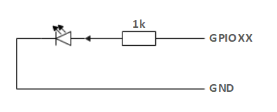
If a certain GPIO is set to the output mode and outputs a high level signal, the circuit connected to the LED is shown in Figure 2 , and the LED will light up.
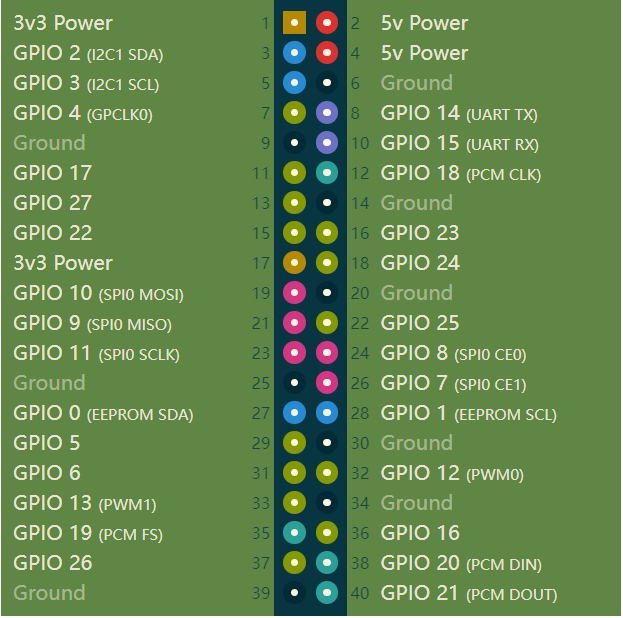
- In the case of using other functions, the IO function is unavailable, and the other function table of the function interface is shown in Figure 3 .
