1、 Introduction
ROS also provides some practical command-line tools, which can be used to obtain various information of different nodes, and the common commands are as follows:
rosnode : Operational nodes
rostopic : Operational topics
rosservice : Operational Services
rosmsg : Manipulating MSG messages
rossrv : Manipulate SRV messages
rosparam : Operational parameters
Official reference URL
2、 Rosnod
rosnode is a command used to obtain node information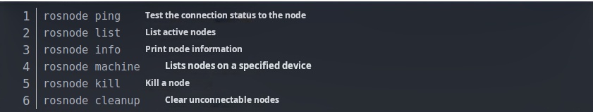
3、rostopic
rostopic contains the rostopic command-line tool to display debugging information about ROS topics, including publishers, subscribers, publishing frequency, and ROS messages. It also contains an experimental Python library for dynamically fetching information about topics and interacting with them.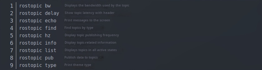
3.1rostopic list
You can call it directly, and the console will print the name of the topic in the current running state
rostopic list -v : Get thread details (e.g. list: number of publishers and subscribers...)
3.2rostopic pub
Commands can be invoked directly to publish messages to subscribers
Publish a string for the Subscriber in the Publish/Subscribe model case that Roboware auto-generated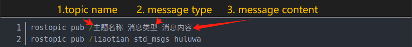
Take the baby turtle as an example to post a sports message: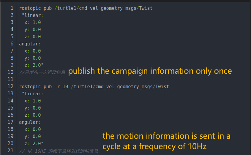
3.3rostpic echo
Gets the current message posted on a specified topic
3.4rostopic info
Get information on current topics
- Message type
- Publisher Information
- Subscriber Information
4、rosservice
rosservice contains the rosservice command-line tool for listing and querying ROSServices.
When you call some services, if you do not configure a path for the related workspace, you need to go to the workspace to call the service source devel/setup.bash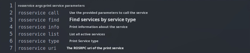
4.1rosservice args
Print service parameters
4.2rosservice call
Invoke service to generate a new turtle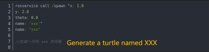
5、rosmsg
rosmsgis a command-line tool used to display information about the type of ROS message.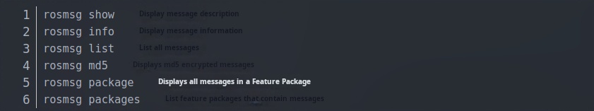
5.1rosmsg package
Lists all MSGs under a package
5.2rosmsg show
Displays a description of the message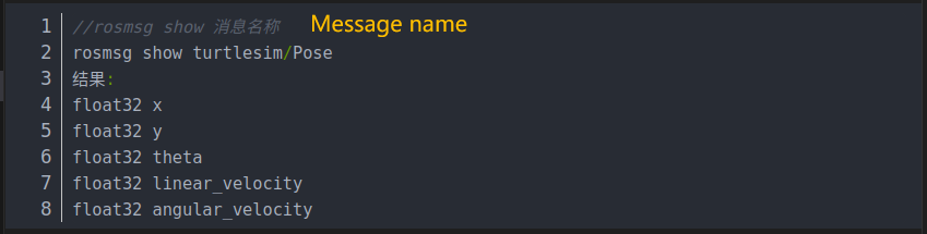
6、rossrv
rossrv is a command-line tool for displaying information about the type of ROS service, and is highly similar to the rosmsg syntax.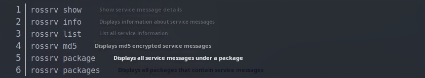
6.1rossrv package

6.2rossrv show
Displays a description of the message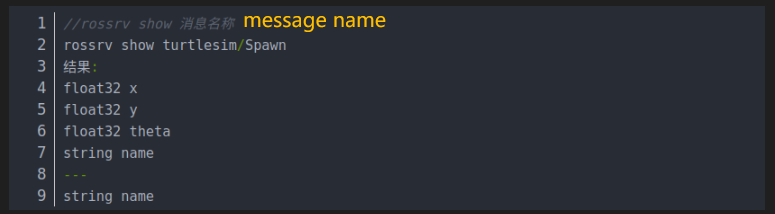
7、rosparam
rosparam includes the rosparam command-line tool for obtaining and setting ROS parameters on a parameter server using a YAML encoding file.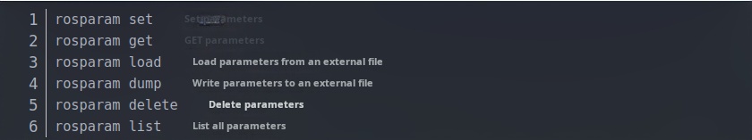
7.1rosparam set
Set the parameters
rosparam set name xxx
7.2rosparam get
Get the parameters
rosparam get name
7.3rosparam delete
Delete the parameter
rosparam delete name
7.4rosparam load(Prepare the yaml file first)
Load parameters from an external file
rosparam load xxx.yaml
7.5rosparam dump
Write out the parameters to an external file
rosparam dump yyy.yaml
8、Introduction to the URDF
- Unified Robot Description Format,The Unified Robot Description Format, or URDF for short. The urdf feature pack in ROS contains a C++ parser for URDF, and URDF files describe the robot model in XML format.
- URDF cannot be used on its own and needs to be combined with Rviz or Gazebo, URDF is just a file that needs to be rendered as a graphical robot model in Rviz or Gazebo.
8.1 urdf file description
Code examples:
Only some of the codes are screenshotted for display: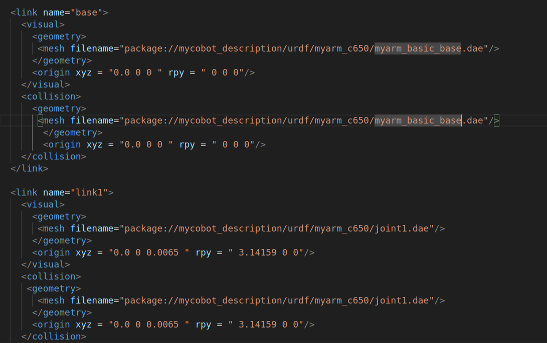
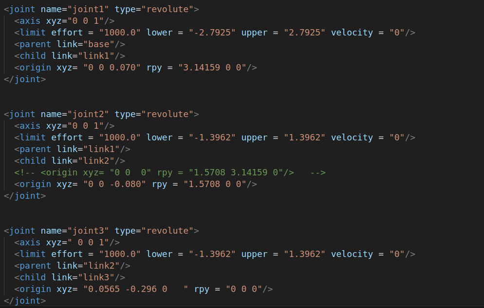
As you can see, the urdf file is not complicated, and is mainly composed of two parts, link and joint, which are constantly repeated.
8.2 link section
The link element describes a rigid body with inertia, visual features, and collision properties
8.2.1 attribute
name: The name used to describe the link itself
8.2.2 element
visual
Visualization properties of the linkage. Used to specify the shape of the linkage display (rectangle, cylinder, etc.), the same link can have multiple visual elements, and the shape of the link is formed by two elements. In general, if the model is more complex, you can generate STL calls after drawing through soildwork, and simple shapes such as adding end effectors can be written directly. At the same time, the position of the geometry can be adjusted here according to the gap between the theoretical and practical models.
namel (Optional) The name of the geometry of the connecting rod.
origin (Optional,defaults to identity if not specified)
- Geometry coordinate system relative to the coordinate system of the linkage.
- xyz (optional: defaults to zero vector) Indicates the offset in the direction of gram, yi, zik, yi, z, yi, z, and z, in meters.
- rpy (optional: defaults to identity if not specified) Represents the rotation of the coordinate axis in the RPY direction, in radians.
geometry (Required)
- The shape of the visualization, which can be one of the following:
- box A rectangle with elements that contain length, width, and height. The origin is in the center.
- cylinder A cylinder, an element containing radius, length. Origin Center.
- sphere A sphere, an element containing a radius. The origin is in the center.
- mesh The grid, which is determined by the file, also provides a scale to delimit its boundaries. Collada .dae files are recommended, and .stl files are also supported, but they must be a local file.
- collision (Optional)
- Collision properties of the linkage. Collision properties are different from the visual properties of the linkage, and simple collision models are often used to simplify calculations. The same link can have multiple collision attribute labels, and the collision attribute representation of the linkage is made up of the set of geometry it defines.
- name (Optional) Specifies the name of the linkage geometry
- origin (Optional,defaults to identity if not specified)
- The reference coordinate system of the collision component is relative to the reference coordinate system of the linkage coordinate system.
- xyz (Optional, Default zero vector) Indicates the offset in the direction of gram, yi, zik, yi, z, yi, z, and z, in meters.
- rpy (Optional, defaults to identity if not specified) Represents the rotation of the coordinate axis in the RPY direction, in radians.
- geometry Same as described above for the geometry element
Details of the elements and what each element does can be found in the official documentation to review
8.3 Joyn part
The joint section describes the kinematics and dynamics of the joint and specifies safety limits for the joint.
8.3.1 Properties of joint:
name:
Specifies a unique name for the joint
type:
Specifies the type of joint, where the type can be one of the following:
- revolute - A hinged joint head that rotates along an axis, the extent of which is specified by the upper and lower limits.
- 连续 - A continuous hinged link head that rotates around an axis with no upper and lower limits.
- Prismatic - A slip joint that slides along an axis, the range of which is specified by the upper and lower limits.
- fixed - It's not really a joint because it can't move. All degrees of freedom are locked. This type of joint does not require shafts, calibration, dynamics, limits, or safety_controller.
- float - This joint allows movement of all 6 degrees of freedom.
- plane - This joint allows movement in a plane perpendicular to the axis.
8.3.2 joint elements
origin (Optional,defaults to identity if not specified) For the transformation from parent link to child link, the joint is located at the origin of the child link, and the position of the connecting rod can be adjusted by modifying this parameter, which can be used to adjust the error between the actual model and the theoretical model, but it is not recommended to modify it significantly, because this parameter affects the position of the connecting rod STL and is easy to affect the collision detection effect.
- xyz (Optional: The default is a zero vector) Represents the offset in the direction of the axis of gram, yi, zik, yi, z, z, z, z
- rpy (Optional: The default is a zero vector) Represents the angle of rotation around a fixed axis: Roll around the x-axis, Pitch around the Y-axis, and Yaw around the Z-axis, expressed in radians.
parent (Required)
- The name of the parent link is a mandatory property.
- The name of the link parent link is the name of the link in the robot structure tree.
child (Required)
- The name of the child link is a mandatory attribute.
- The name of the link child link is the name of the link in the robot structure tree.
axis(Optional: Default is (1,0,0))
- The axis of the joint is in the coordinate system of the joint. This is the axis of rotation (revolute joint), the axis on which the prismatic joint moves, and is the standard plane of the Planar joint. This axis is specified in the joint coordinate system. Modify this parameter to adjust the axis around which the rotation of the joint is rotated, which is often used to adjust the direction of rotation, if the rotation direction of the model is opposite to the actual one, you only need to multiply -1. Fixed and floating joints do not need this element.
- xyz(required) The gram, yi, zik, yi, z, yi, yi, yi, zi, zi, zi, yi, zi, yi, z
calibration (Optional)
- The reference point of the joint, which is used to correct the absolute position of the joint.
- rising (Optional) When the joint is moving forward, the reference point triggers a rising edge.
- falling (Optional) When the joint is moving forward, the reference point triggers a descending edge.
dynamics(Optional)
- This element is used to specify the physical properties of the joint. Its value is used to describe the modeling performance of the joint, especially when simulating.
limit (Required when the joint is rotated or moved)
- This element is a joint kinematic constraint.
- lower (Optional, The default value is 0) Specifies the property of the lower bound of the joint's range of motion (in radians for revolute joints and meters for prismatic joints), which is ignored for continuous joints.
- upper (Optional, The default value is 0) Specifies the property of the upper bound of the joint's range of motion (in radians for revolute joints and meters for prismatic joints), which is ignored for continuous joints.
- effort (Required) This property specifies the maximum force at which the joint runs.
- velocity (required) This property specifies the maximum speed at which the joint runs.
Details of the elements and what each element does can be found in Documentation to review