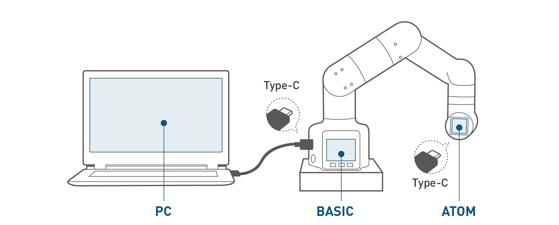
Communication and message commands
Note: To use the communication protocol for direct communication, you need to burn transponder in basic and the latest version of atomMain in atom
Robotic arm motion parameters
| Joint | *Joint minimum value ° | Joint maximum value ° | Joint maximum speed °/s | Joint maximum acceleration °/s² |
|---|---|---|---|---|
| J1 | -168 | 168 | 150 | 200 |
| J2 | -135 | 135 | 150 | 200 |
| J3 | -150 | 150 | 150 | 200 |
| J4 | -145 | 145 | 150 | 200 |
| J5 | -165 | 165 | 150 | 200 |
| J6 | -180 | 180 | 150 | 200 |
| Axis | *Minimum value of coordinate mm | Maximum value of coordinate mm | Maximum velocity of coordinate mm/s | Maximum acceleration of coordinate mm/s² |
|---|---|---|---|---|
| x | -281.45 | 281.45 | 100 | 400 |
| y | -281.45 | 281.45 | 100 | 400 |
| z | -70 | 412.76 | 100 | 400 |
| rx | -180° | 180° | 40° | 66°/s² |
| ry | -180° | 180° | 40° | 66°/s² |
| rz | -180° | 180° | 40° | 66°/s² |
USB Communication Settings
Please make sure your communication settings are as follows
Bus interface: USB Type-C connection
Baud rate: 115200
- Data bits: 8
- Parity: None
- Stop bits: 1
Command frame description and single command analysis
The host Basic sends data to the slave, and the slave parses the data after receiving it. If the command contains a return value, the slave will return it to the host within 500ms.
Command frame sending and receiving format
All commands are in hexadecimal, and the sending and receiving formats are consistent.
Each communication command must contain the following 5 parts, of which 3 and 4 can be empty.
- 1 Command header: 0xFE 0xFE
- Fixed
- Required
- 2 Effective command length: 0x02 ~ 0x10
- Length of all the following commands
- Required
- 3 Command number: 00 ~ 8F
- Multiple commands have been developed
- Can be empty
- 4 Command content: Several
- Can be empty
- 5 Command end: 0XFA
- Fixed
- Required
Command parsing
The host Basic sends data to the slave, and the slave parses the data after receiving it. If the command contains a return value, the slave will return it to the host within 500ms.
| Type | Data description | Data length | Description |
|---|---|---|---|
| Command frame | Header byte 0 | 1 | Frame header identification, 0XFE |
| Header byte 1 | 1 | Frame header identification, 0XFE | |
| Data length byte | 1 | Different instructions correspond to different lengths of data | |
| Command byte | 1 | Depends on different commands | |
| Data frame | Data | 0-16 | Data attached to the command, depending on different commands |
| End frame | End byte | 1 | Stop bit, 0XFA |
Single command analysis
Robot power on
| Data field | Description | Data |
|---|---|---|
| Data[0] | Identification frame | 0XFE |
| Data[1] | Identification frame | 0XFE |
| Data[2] | Data length frame | 0X02 |
| Data[3] | Command frame | 0X10 |
| Data[4] | End frame | 0XFA |
Serial port sending example: FE FE 02 10 FA
No return value
Robotic arm power off and disconnect
| Data field | Description | Data |
|---|---|---|
| Data[0] | Identification frame | 0XFE |
| Data[1] | Identification frame | 0XFE |
| Data[2] | Data length frame | 0X02 |
| Data[3] | Command frame | 0X11 |
| Data[4] | End frame | 0XFA |
Serial port sending example: FE FE 02 11 FA
No return value
Atom status query
| Data field | Description | Data |
|---|---|---|
| Data[0] | Identification frame | 0XFE |
| Data[1] | Identification frame | 0XFE |
| Data[2] | Data length frame | 0X02 |
| Data[3] | Command frame | 0X12 |
| Data[4] | End frame | 0XFA |
Serial port sending example: FE FE 02 12 FA
Return data structure
| Data field | Description | Data |
|---|---|---|
| Data[0] | Return frame header | 0XFE |
| Data[1] | Return frame header | 0XFE |
| Data[2] | Return length frame | 0X03 |
| Data[3] | Return command frame | 0X12 |
| Data[4] | Power on/off | 0X01/0X00 |
| Data[5] | End frame | 0XFA |
Assume that Atom is powered on
Serial port return example: FE FE 03 12 01 FA
Robotic arm only powers off
| Data field | Description | Data |
|---|---|---|
| Data[0] | Identification frame | 0XFE |
| Data[1] | Identification frame | 0XFE |
| Data[2] | Data length frame | 0X02 |
| Data[3] | Command frame | 0X13 |
| Data[4] | End frame | 0XFA |
Serial port sending example: FE FE 02 13 FA
No return value
Robot system detection is normal
| Data field | Description | Data |
|---|---|---|
| Data[0] | Identification frame | 0XFE |
| Data[1] | Identification frame | 0XFE |
| Data[2] | Data length frame | 0X02 |
| Data[3] | Command frame | 0X14 |
| Data[4] | End frame | 0XFA |
Serial port sending example: FE FE 02 14 FA
Return data structure
| Data field | Description | Data |
|---|---|---|
| Data[0] | Return frame header | 0XFE |
| Data[1] | Return frame header | 0XFE |
| Data[2] | Return length frame | 0X03 |
| Data[3] | Return command frame | 0X14 |
| Data[4] | Normal connection/disconnection | 0X01/0X00 |
| Data[5] | End frame | 0XFA |
Assuming Atom connection is successful
Serial port return example: FE FE 03 14 01 FA
Command refresh mode switch (set interpolation/refresh motion mode)
| Data field | Description | Data |
|---|---|---|
| Data[0] | Identification frame | 0XFE |
| Data[1] | Identification frame | 0XFE |
| Data[2] | Data length frame | 0X03 |
| Data[3] | Command frame | 0X16 |
| Data[4] | Command frame | 0X01/0X00 |
| Data[5] | End frame | 0XFA |
Set to refresh motion mode:
Serial port sending example: FE FE 03 16 01 FA
Set to interpolation motion mode:
Serial port sending example: FE FE 03 16 00 FA
Robot free mode (turn off all torque output)
| Data field | Description | Data |
|---|---|---|
| Data[0] | Identification frame | 0XFE |
| Data[1] | Identification frame | 0XFE |
| Data[2] | Data length frame | 0X03 |
| Data[3] | Command frame | 0X1A |
| Data[4] | Open/Close | 01/00 |
| Data[5] | End frame | 0XFA |
Set to free movement mode:
Serial port sending example: FE FE 03 1A 01 FA
Check whether it is free mode
| Data field | Description | Data |
|---|---|---|
| Data[0] | Identification frame | 0XFE |
| Data[1] | Identification frame | 0XFE |
| Data[2] | Data length frame | 0X02 |
| Data[3] | Command frame | 0X1B |
| Data[5] | End frame | 0XFA |
Serial port sending example: FE FE 02 1B FA
Return data structure
| Data field | Description | Data |
|---|---|---|
| Data[0] | Return frame header | 0XFE |
| Data[1] | Return frame header | 0XFE |
| Data[2] | Return length frame | 0X03 |
| Data[3] | Return instruction frame | 0X1B |
| Data[4] | Open/Close | 0X01/0X00 |
| Data[5] | End frame | 0XFA |
Assuming Atom is in free movement mode
Serial port return example: FE FE 03 1B 01 FA
Read angle (read movement information)
| Data field | Description | Data |
|---|---|---|
| Data[0] | Identify frame | 0XFE |
| Data[1] | Identification frame | 0XFE |
| Data[2] | Data length frame | 0X02 |
| Data[3] | Command frame | 0X20 |
| Data[4] | End frame | 0XFA |
Serial port sending example: FE FE 02 20 FA
Return data structure
| Data field | Description | Data |
|---|---|---|
| Data[0] | Return frame header | 0XFE |
| Data[1] | Return frame header | 0XFE |
| Data[2] | Return length frame | 0X0E |
| Data[3] | Return command frame | 0X20 |
| Data[4] | No. 1 servo angle high | Angle1_high |
| Data[5] | No. 1 servo angle low | Angle1_low |
| Data[6] | Angle 2 high position | Angle2_high |
| Data[7] | Angle 2 low position | Angle2_low |
| Data[8] | Angle 3 high position | Angle3_high |
| Data[9] | Angle 3 low position | Angle3_low |
| Data[10] | Angle 4 high position | Angle4_high |
| Data[11] | Angle 4 low position | Angle4_low |
| Data[12] | Angle 5 high position | Angle5_high |
| Data[13] | Angle 5 low position | Angle5_low |
| Data[14] | Angle 6 high position | Angle6_high |
| Data[15] | Angle 6 low position | Angle6_low |
| Data[16] | End frame | 0XFA |
Serial port return example: FE FE 0E 20 00 8C 00 3D FF E6 FF 3F 00 AF FF 51 FA
How to get the angle of joint 1
temp = angle1_low+angle1_high*256
Angle1=(temp \ 33000 ?(temp – 65536) : temp)/100
Calculation method: angle value low + angle value high multiplied by 256 First determine whether it is greater than 33000 If it is greater than 33000, subtract 65536 and finally divide by 100. If it is less than 33000, directly divide by 100
(The same applies to the rest)
Send a single angle
| Data field | Description | Data |
|---|---|---|
| Data[0] | Identify frame | 0XFE |
| Data[1] | Identification frame | 0XFE |
| Data[2] | Data length frame | 0X06 |
| Data[3] | Command frame | 0X21 |
| Data[4] | Servo serial number | joint_no |
| Data[5] | Angle value high | angle_high |
| Data[6] | Angle value low | angle_low |
| Data[7] | Specified speed | sp |
| Data[8] | End frame | 0XFA |
Move servo No. 1 to zero position at 20% speed
Serial port sending example: FE FE 06 21 01 00 00 14 FA
joint_no value range: 1~6
angle_high: data type byte
Calculation method: multiply the angle value by 100 and convert it to int format first Then take the high byte of the hexadecimal
angle_low: data type byte
Calculation method: multiply the angle value by 100, convert it to int format, and then take the low byte of the hexadecimal
No return value
Send all angles
| Data field | Description | Data |
|---|---|---|
| Data[0] | Identification frame | 0XFE |
| Data[1] | Identification frame | 0XFE |
| Data[2] | Data length frame | 0X0F |
| Data[3] | Command frame | 0X22 |
| Data[4] | No. 1 servo angle value high byte | Angle1_high |
| Data[5] | No. 1 servo angle value low byte | Angle1_low |
| Data[6] | No. 2 servo angle value high byte | Angle2_high |
| Data[7] | No. 2 servo angle value low byte | Angle2_low |
| Data[8] | No. 3 servo angle value high byte | Angle3_high |
| Data[9] | No. 3 servo angle value low byte | Angle3_low |
| Data[10] | High byte of the angle value of Servo No. 4 | Angle4_ high |
| Data[11] | Low byte of the angle value of Servo No. 4 | Angle4_ low |
| Data[12] | High byte of the angle value of Servo No. 5 | Angle5_ high |
| Data[13] | Low byte of the angle value of Servo No. 5 | Angle5_ low |
| Data[14] | High byte of the angle value of Servo No. 6 | Angle6_ high |
| Data[15] | Low byte of the angle value of Servo No. 6 | Angle6_ low |
| Data[16] | Specified speed | Sp |
| Data[17] | End frame | 0XFA |
Send all angles to zero/restore the machine to zero position and move at 30% speed
Serial port sending example: FE FE 0F 22 00 00 00 00 00 00 00 00 00 00 00 00 1E FA
angle1_high: data type byte
Calculation method: multiply the angle value of servo No. 1 by 100, convert it to int format first, and then take the high byte of hexadecimal
angle1_low: data type byte
Calculation method: multiply the angle value of servo No. 1 by 100, convert it to int format first, and then take the low byte of hexadecimal
(The same applies to the rest)
No return value
Read all coordinates
| Data field | Description | Data |
|---|---|---|
| Data[0] | Identification frame | 0XFE |
| Data[1] | Identification frame | 0XFE |
| Data[2] | Data length frame | 0X02 |
| Data[3] | Command frame | 0X23 |
| Data[4] | End frame | 0XFA |
Serial port sending example: FE FE 02 23 FA
Return data structure
| Data field | Description | Data |
|---|---|---|
| Data[0] | Return frame header | 0XFE |
| Data[1] | Return frame header | 0XFE |
| Data[2] | Return length frame | 0X0E |
| Data[3] | Return instruction frame | 0X23 |
| Data[4] | Specify x coordinate high | x_high |
| Data[5] | Specify x coordinate low | x_low |
| Data[6] | Specify y coordinate high | y_high |
| Data[7] | Specify y coordinate low | y_low |
| Data[8] | Specify z coordinate high | z_high |
| Data[9] | Specify z coordinate low | z_low |
| Data[10] | Specify rx coordinate high | rx_high |
| Data[11] | Specify the low bit of the rx coordinate | rx_low |
| Data[12] | Specify the high bit of the ry coordinate | ry_high |
| Data[13] | Specify the low bit of the ry coordinate | ry_low |
| Data[14] | Specify the high bit of the rz coordinate | rz_high |
| Data[15] | Specify the low bit of the rz coordinate | rz_low |
| Data[16] | End frame | 0XFA |
Serial port return example: FE FE 0E 23 01 BC FD A0 10 15 DC 66 FF 54 DE 21 FA
How to get the x coordinate
temp = x_low + x_high*256
x coordinate = (temp \ 33000 ?(temp – 65536) : temp)/10
Calculation method: x coordinate value low bit + x coordinate value high bit multiplied by 256 First determine whether it is greater than 33000 If it is greater than 33000, subtract 65536 and finally divide by 100. If it is less than 33000, just divide by 10 directly
(The same applies to y coordinates and z coordinates)
How to get the rx coordinate
temp = rx_low + rx_high*256
x coordinate = (temp \ 33000 ?(temp – 65536) : temp)/100
Calculation method: x coordinate value low bit + x coordinate value high bit multiplied by 256 First determine whether it is greater than 33000 If it is greater than 33000, subtract 65536 and finally divide by 100. If it is less than 33000, just divide by 100 directly
(The same applies to ry coordinates and rz coordinates)
Send individual coordinate parameters
| Data field | Description | Data |
|---|---|---|
| Data[0] | Identification frame | 0XFE |
| Data[1] | Identification frame | 0XFE |
| Data[2] | Data length frame | 0X06 |
| Data[3] | Command frame | 0X24 |
| Data[4] | axis | x/y/z/rx/ry/rz |
| Data[5] | Specify xyz/rxryrz parameter high | xyz/rxryrz_high |
| Data[6] | Specify xyz/rxryrz parameter low | xyz/rxryrz_low |
| Data[7] | Specify speed | Sp |
| Data[8] | End frame | 0XFA |
Set X coordinate to 200 and target speed to 20
Serial port sending example: FE FE 06 24 01 07 D0 14 FA
Specify axis: data type byte
Value range: 1~6
xyz_high: data type byte
Calculation method: x/y/z coordinate value multiplied by 10 and then take the high byte of hexadecimal
xyz_low: data type byte
Calculation method: x/y/z coordinate value multiplied by 10 and then take the low byte of hexadecimal
rxryrz_high: data type byte
Calculation method: rx/ry/rz multiplied by 100 and then take the high byte of hexadecimal
rxryrz_low: data type byte
Calculation method: rx/ry/rz multiplied by 100 and then take the low byte of hexadecimal
No return value
Send all coordinate parameters
| Data field | Description | Data |
|---|---|---|
| Data[0] | Identification frame | 0XFE |
| Data[1] | Identification frame | 0XFE |
| Data[2] | Data length frame | 0X10 |
| Data[3] | Command frame | 0X25 |
| Data[4] | Specify x coordinate high | x_high |
| Data[5] | Specify x coordinate low | x_low |
| Data[6] | Specify y coordinate high | y_high |
| Data[7] | Specify y coordinate low | y_low |
| Data[8] | Specify z coordinate high | z_high |
| Data[9] | Specify z coordinate low | z_low |
| Data[10] | Specify rx coordinate high | rx_high |
| Data[11] | Specify the low bit of rx coordinate | rx_low |
| Data[12] | Specify the high bit of ry coordinate | ry_high |
| Data[13] | Specify the low bit of ry coordinate | ry_low |
| Data[14] | Specify the high bit of rz coordinate | rz_high |
| Data[15] | Specify the low bit of rz coordinate | rz_low |
| Data[16] | Specify the speed | Sp |
| Data[17] | Mode | 0X01 |
| Data[18] | End frame | 0XFA |
Set the target position of the end of the robot arm (150.3, -68.7, 101.8, 10.18, 0, -90), target speed 10
Serial port sending example: FE FE 10 25 05 DF FD 51 03 FA BC 30 00 00 DC D8 0A 01 FA
x_high: Data type byte
Calculation method: x coordinate multiplied by 10 and then take the high byte of hexadecimal
x_low: Data type byte
Calculation method: x coordinate multiplied by 10 and then take the low byte of hexadecimal
(The same applies to y-axis coordinates and z-axis coordinates)
rx_high: Data type byte
Calculation method: rx coordinate value multiplied by 100 and then take the high byte of hexadecimal
rx_low: Data type byte
Calculation method: rx coordinate value multiplied by 100 and then take the low byte of hexadecimal
(The same applies to ry-axis coordinates and rz-axis coordinates)
No return value
Program pause
| Data field | Description | Data |
|---|---|---|
| Data[0] | Identification frame | 0XFE |
| Data[1] | Identification frame | 0XFE |
| Data[2] | Data length frame | 0X02 |
| Data[3] | Command frame | 0X26 |
| Data[4] | End frame | 0XFA |
Serial port sending example: FE FE 02 26 FA
No return value
Is the program paused?
| Data field | Description | Data |
|---|---|---|
| Data[0] | Identification frame | 0XFE |
| Data[1] | Identification frame | 0XFE |
| Data[2] | Data length frame | 0X02 |
| Data[3] | Command frame | 0X27 |
| Data[4] | End frame | 0XFA |
Serial port sending example: FE FE 02 27 FA
Return data structure
| Data field | Description | Data |
|---|---|---|
| Data[0] | Return frame header | 0XFE |
| Data[1] | Return frame header | 0XFE |
| Data[2] | Return length frame | 0X03 |
| Data[3] | Return command frame | 0X27 |
| Data[4] | Pause/unpause | 0X01/0X00 |
| Data[5] | End frame | 0XFA |
Assume the program is in pause state
Serial port return example: FE FE 03 12 01 FA
Program resume
| Data field | Description | Data |
|---|---|---|
| Data[0] | Identification frame | 0XFE |
| Data[1] | Identification frame | 0XFE |
| Data[2] | Data length frame | 0X02 |
| Data[3] | Command frame | 0X28 |
| Data[4] | End frame | 0XFA |
Serial port sending example: FE FE 02 28 FA
No return value
Program stop
| Data field | Description | Data |
|---|---|---|
| Data[0] | Identification frame | 0XFE |
| Data[1] | Identification frame | 0XFE |
| Data[2] | Data length frame | 0X02 |
| Data[3] | Command frame | 0X29 |
| Data[4] | End frame | 0XFA |
Serial port sending example: FE FE 02 28 FA
No return value
Whether the point is reached
| Data field | Description | Data |
|---|---|---|
| Data[0] | Identification frame | 0XFE |
| Data[1] | Identification frame | 0XFE |
| Data[2] | Data length frame | 0X0E/0X0F |
| Data[3] | Command frame | 0X2A |
| Data[4] | Coordinate x high byte/No. 1 servo angle value high byte | x_high/Angle1_high |
| Data[5] | Coordinate x low byte/No. 1 servo angle value low byte | x_low/Angle1_low |
| Data[6] | Coordinate y high byte/No. 2 servo angle value high byte | y_high/Angle2_high |
| Data[7] | Coordinate y low byte/No. 2 servo angle value low byte | y_low/Angle2_low |
| Data[8] | Coordinate z high byte/No. 3 servo angle value high byte | z_high/Angle3_high |
| Data[9] | Coordinate z low byte/No. 3 servo angle value low byte | z_low/Angle3_low |
| Data[10] | Coordinate rx high bit/No. 4 servo angle value high byte | rx_high/Angle4_high |
| Data[11] | Coordinate rx low bit/No. 4 servo angle value low byte | rx_low/Angle4_low |
| Data[12] | Coordinate ry high bit/No. 5 servo angle value high byte | ry_high/Angle5_high |
| Data[13] | Coordinate ry low bit/No. 5 servo angle value low byte | ry_low/Angle5_low |
| Data[14] | Coordinate rz high bit/No. 6 servo angle value high byte | rz_high/Angle6_high |
| Data[15] | Coordinate rz low bit/No. 6 servo angle value low byte | rz_low/Angle6_low |
| Data[16] | Coordinate/angle | 0X01/0X00 |
| Data[17] | End frame | 0XFA |
Judge whether the robot has reached the origin
Serial port sending example: FE FE 0F 2A 00 00 00 00 00 00 00 00 00 00 00 00 00 FA
x_high: data type byte
Calculation method: x coordinate multiplied by 10, first converted to int type, then take the hexadecimal high byte
x_low: data type byte
Calculation method: x coordinate multiplied by 10, first converted to int type, then take the hexadecimal low byte
(The same applies to y-axis coordinates and z-axis coordinates)
rx_high: data type byte
Calculation method: rx coordinate multiplied by 100, first converted to int type, then take the hexadecimal high byte
rx_low: data type byte
Calculation method: rx coordinate multiplied by 100, first converted to int type Then take the low byte of hexadecimal
(The same applies to the ry axis coordinates and the rz axis coordinates)
angle_high: data type byte
Calculation method: multiply the angle value by 100, convert it to int format first, and then take the high byte of hexadecimal
angle_low: data type byte
Calculation method: multiply the angle value by 100, convert it to int format first, and then take the low byte of hexadecimal
Type: data type byte (not used yet)
Return data structure
| Data field | Description | Data |
|---|---|---|
| Data[0] | Return frame header | 0XFE |
| Data[1] | Return frame header | 0XFE |
| Data[2] | Return length frame | 0X03 |
| Data[3] | Return instruction frame | 0X2a |
| Data[4] | Arrived point/unreached point | 0X01/0X00 |
| Data[5] | End frame | 0XFA |
Assume the robot arm has not reached the specified point
Serial port return example: FE FE 03 2A 00 FA
Robotic arm motion detection
| Data field | Description | Data |
|---|---|---|
| Data[0] | Identification frame | 0XFE |
| Data[1] | Identification frame | 0XFE |
| Data[2] | Data length frame | 0X02 |
| Data[3] | Command frame | 0X2B |
| Data[4] | End frame | 0XFA |
Serial port sending example: FE FE 02 2B FA
Return data structure
| Data field | Description | Data |
|---|---|---|
| Data[0] | Return frame header | 0XFE |
| Data[1] | Return frame header | 0XFE |
| Data[2] | Return length frame | 0X03 |
| Data[3] | Return command frame | 0X2B |
| Data[4] | Moving/Not Moving | 0X01/0X00 |
| Data[5] | End Frame | 0XFA |
Assuming the program is in motion
Serial port return example: FE FE 03 2B 01 FA
jog-Joint direction movement
| Data field | Description | Data |
|---|---|---|
| Data[0] | Identification frame | 0XFE |
| Data[1] | Identification frame | 0XFE |
| Data[2] | Data length frame | 0X05 |
| Data[3] | Command frame | 0X30 |
| Data[4] | Joint servo number | Joint |
| Data[5] | Joint servo direction | direction |
| Data[6] | Specified speed | sp |
| Data[7] | End Frame | 0XFA |
Set servo No. 1 to rotate clockwise at 20% speed
Serial port sending example: FE FE 05 30 01 01 14 FA
Joint number range: 1~6
di: Data type byte Value range 0 and 1
sp: Data type byte Value range 0-100
No return value
jod-absolute control
| Data field | Description | Data |
|---|---|---|
| Data[0] | Identification frame | 0XFE |
| Data[1] | Identification frame | 0XFE |
| Data[2] | Data length frame | 0X06 |
| Data[3] | Command frame | 0X31 |
| Data[4] | Joint servo number | Joint |
| Data[5] | Joint servo angle value high byte | Angle_high |
| Data[6] | Low byte of joint servo angle value | Angle_low |
| Data[7] | Specified speed | sp |
| Data[8] | End frame | 0XFA |
Set servo No. 1 to 45°, speed 20
Serial port sending example: FE FE 06 31 01 11 94 14 FA
Joint number value range: 1~6
Angle_high: Data type byte
Calculation method: Multiply the angle value by 100, convert it to int format first, and then take the high byte of hexadecimal
Angle_low: Data type byte
Calculation method: Multiply the angle value by 100, convert it to int format first, and then take the low byte of hexadecimal
sp: Data type byte, value range 0-100
No return value
jog-coordinate direction movement
| Data field | Description | Data |
|---|---|---|
| Data[0] | Identification frame | 0XFE |
| Data[1] | Identification frame | 0XFE |
| Data[2] | Data length frame | 0X05 |
| Data[3] | Command frame | 0X32 |
| Data[4] | Specified coordinates | axis |
| Data[5] | Joint servo direction | di |
| Data[6] | Specified speed | sp |
| Data[7] | End frame | 0XFA |
Set the robot arm to move in the x direction, speed 20
Serial port sending example: FE FE 06 32 01 01 14 FA
axis value range: 1~6, representing x, y, z, rx, ry, rz respectively
di: data type byte value range 0 and 1
sp: data type byte value range 0-100
No return value
jog-stepping mode
| Data field | Description | Data |
|---|---|---|
| Data[0] | Identification frame | 0XFE |
| Data[1] | Identification frame | 0XFE |
| Data[2] | Data length frame | 0X06 |
| Data[3] | Command frame | 0X33 |
| Data[4] | Joint servo serial number | Joint |
| Data[5] | Joint servo angle value high byte | Angle_high |
| Data[6] | Joint servo angle value low byte | Angle_low |
| Data[7] | Specified speed | sp |
| Data[8] | End frame | 0XFA |
Set the angle of servo No. 1 to increase by 45 and rotate at 20% speed
Serial port sending example: FE FE 06 33 01 11 94 14 FA
Joint serial number value range: 1~6
Angle_high: Data type byte
Calculation method: Multiply the angle value by 100, convert to int format first, and then take the high byte of hexadecimal
Angle_low: Data type byte
Calculation method: Multiply the angle value by 100, convert to int format first, and then take the low byte of hexadecimal
sp: Data type byte Value range 0-100
No return value
Send potential value
| Data field | Description | Data |
|---|---|---|
| Data[0] | Identification frame | 0XFE |
| Data[1] | Identification frame | 0XFE |
| Data[2] | Data length frame | 0X05 |
| Data[3] | Command frame | 0X3A |
| Data[4] | Joint servo serial number | Joint |
| Data[5] | Potential value high | Encoder_high |
| Data[6] | Potential value low | Encoder_low |
| Data[7] | Specified speed | sp |
| Data[8] | End frame | 0XFA |
Example, set joint 5 to 2048 potential and rotate at 20% speed
Serial port sending example: FE FE 05 3A 05 08 00 14 FA
Joint number range: 1~6
Joint: Data type byte
Encoder_high: Data type byte
Calculation method: Take the high bit of the potential value (hexadecimal)
Encoder_low: Data type byte
Calculation method: Take the low bit of the potential value (hexadecimal)
No return value
Get potential value
| Data field | Description | Data |
|---|---|---|
| Data[0] | Identify frame | 0XFE |
| Data[1] | Identify frame | 0XFE |
| Data[2] | Data length frame | 0X03 |
| Data[3] | Command frame | 0X3B |
| Data[4] | Joint number | joint |
| Data[5] | End frame | 0XFA |
Get the potential value of servo No. 2
Serial port sending example: FE FE 03 3B 02 FA
Joint number range: 1-6
Return data structure
| Data field | Description | Data |
|---|---|---|
| Data[0] | Return identification frame | 0XFE |
| Data[1] | Return identification frame | 0XFE |
| Data[2] | Return data length frame | 0X04 |
| Data[3] | Return command frame | 0X3B |
| Data[4] | Servo potential value high | Encoder_high |
| Data[5] | Servo potential value low | Encoders_low |
| Data[6] | End frame | 0XFA |
Serial port return example: FE FE 04 3B 08 07 FA
How to calculate the potential value
Potential value = potential value low bit + potential value high bit * 256
Send the potential values of six servos
| Data field | Description | Data |
|---|---|---|
| Data[0] | Identification frame | 0XFE |
| Data[1] | Identification frame | 0XFE |
| Data[2] | Data length frame | 0X0F |
| Data[3] | Command frame | 0X3C |
| Data[4] | High byte of potential value of servo No. 1 | encoder_1_high |
| Data[5] | Low byte of potential value of servo No. 1 | encoder_1_low |
| Data[6] | High byte of potential value of servo No. 2 | encoder_2_high |
| Data[7] | Low byte of potential value of servo No. 2 | encoder_2_low |
| Data[8] | High byte of potential value of servo No. 3 | encoder_3_high |
| Data[9] | Low byte of potential value of servo No. 3 | encoder_3_low |
| Data[10] | No. 4 servo potential value high byte | encoder_4_high |
| Data[11] | No. 4 servo potential value low byte | encoder_4_low |
| Data[12] | No. 5 servo potential value high byte | encoder_5_high |
| Data[13] | No. 5 servo potential value low byte | encoder_5_low |
| Data[14] | No. 6 servo potential value high byte | encoder_6_high |
| Data[15] | No. 6 servo potential value low byte | encoder_6_low |
| Data[16] | Specified speed | Sp |
| Data[17] | End frame | 0XFA |
The potential value of all motors sent is 2048, and the speed is 20
Serial port sending example: FE FE 0F 3C 08 00 08 00 08 00 08 00 08 00 08 00 14 FA
(Refer to the above for sending a single potential value)
encoder_1_high: Data type byte
Calculation method: The potential value of servo No. 1 is first converted to int type and then the hexadecimal high byte is taken
encoder_1_low: Data type byte
Calculation method: The potential value of servo No. 1 is first converted to int type and then the hexadecimal low byte is taken
(The same applies to the rest)
Sp: Data type byte Value range: 0~100
No return value
Read the potential values of six servos
| Data field | Description | Data |
|---|---|---|
| Data[0] | Identification frame | 0XFE |
| Data[1] | Identification frame | 0XFE |
| Data[2] | Data length frame | 0X02 |
| Data[3] | Command frame | 0X3D |
| Data[4] | End frame | 0XFA |
Serial port sending example: FE FE 02 3D FA
Return data structure
| Data field | Description | Data |
|---|---|---|
| Data[0] | Identification frame | 0XFE |
| Data[1] | Identification frame | 0XFE |
| Data[2] | Data length frame | 0X0E |
| Data[3] | Command frame | 0X3D |
| Data[4] | High byte of the potential value of Servo No. 1 | encoder_1_high |
| Data[5] | Low byte of the potential value of Servo No. 1 | encoder_1_low |
| Data[6] | High byte of the potential value of Servo No. 2 | encoder_2_high |
| Data[7] | Low byte of the potential value of Servo No. 2 | encoder_2_low |
| Data[8] | Servo 3 potential value high byte | encoder_3_high |
| Data[9] | Servo 3 potential value low byte | encoder_3_low |
| Data[10] | Servo 4 potential value high byte | encoder_4_high |
| Data[11] | Servo 4 potential value low byte | encoder_4_low |
| Data[12] | Servo 5 potential value high byte | encoder_5_high |
| Data[13] | Servo 5 potential value low byte | encoder_5_low |
| Data[14] | Servo 6 potential value high byte | encoder_6_high |
| Data[15] | Servo 6 potential value low byte | encoder_6_low |
| Data[16] | End frame | 0XFA |
Assume that all joints of the current robot arm are at 0 position
Serial port return example: FE FE 0E 3D 08 00 08 00 08 00 08 00 08 00 08 00 FA
How to calculate the potential value
Potential value = potential value low bit + potential value high bit * 256
Set speed
| Data field | Description | Data |
|---|---|---|
| Data[0] | Identification frame | 0XFE |
| Data[1] | Identification frame | 0XFE |
| Data[2] | Data length frame | 0X03 |
| Data[3] | Instruction frame | 0X41 |
| Data[4] | Specified speed | sp |
| Data[5] | End frame | 0XFA |
Sp: Data type byte Value range: 0~100
Set the current speed to 50%
Serial port sending example: FE FE 03 41 32 FA
No return value
Read the minimum angle of the joint
| Data field | Description | Data |
|---|---|---|
| Data[0] | Identification frame | 0XFE |
| Data[1] | Identification frame | 0XFE |
| Data[2] | Data length frame | 0X03 |
| Data[3] | Command frame | 0X4A |
| Data[4] | Joint servo serial number | Joint_number |
| Data[5] | End frame | 0XFA |
Read the minimum angle of joint No. 2
Serial port sending example: FE FE 03 4A 02 FA
joint_no value range: 1-6
Return data structure
| Data field | Description | Data |
|---|---|---|
| Data[0] | Return identification frame | 0XFE |
| Data[1] | Return identification frame | 0XFE |
| Data[2] | Return data length frame | 0X05 |
| Data[3] | Return command frame | 0X4A |
| Data[4] | Joint servo number | Joint_number |
| Data[5] | Servo angle value high | Angle_high |
| Data[6] | Servo angle value low | Angle_low |
| Data[7] | End frame | 0XFA |
Serial port return example: FE FE 05 4A 02 F9 F2 FA
How to get the minimum angle of the joint
temp = angle1_low+angle1_high*256
Angle1=(temp \ 33000 ?(temp – 65536) : temp)/10
Calculation method: angle value low + angle value high multiplied by 256 First determine whether it is greater than 33000 If it is greater than 33000, subtract 65536 and finally divide by 10. If it is less than 33000, divide by 10 directly
Read the maximum angle of the joint
| Data field | Description | Data |
|---|---|---|
| Data[0] | Identification frame | 0XFE |
| Data[1] | Identification frame | 0XFE |
| Data[2] | Data length frame | 0X03 |
| Data[3] | Command frame | 0X4B |
| Data[4] | Joint servo serial number | joint_number |
| Data[5] | End frame | 0XFA |
joint_no value range: 1-6
Read the maximum angle of joint 2
Serial port sending example: FE FE 03 4B 02 FA
Return data structure
| Data field | Description | Data |
|---|---|---|
| Data[0] | Return identification frame | 0XFE |
| Data[1] | Return identification frame | 0XFE |
| Data[2] | Return data length frame | 0X05 |
| Data[3] | Return command frame | 0X4B |
| Data[4] | Joint servo number | joint_number |
| Data[5] | Servo angle value high | Angle_high |
| Data[6] | Servo angle value low | Angle_low |
| Data[7] | End frame | 0XFA |
Serial port return example: FE FE 05 4B 02 06 72 FA
How to get the maximum angle of the joint
temp = angle1_low+angle1_high*256
Angle1=(temp \ 33000 ?(temp – 65536) : temp)/10
Calculation method: angle value low bit + angle value high bit multiplied by 256 First determine whether it is greater than 33000 If it is greater than 33000, subtract 65536 and finally divide by 10. If it is less than 33000, just divide by 10
Set the minimum angle of the joint
| Data field | Description | Data |
|---|---|---|
| Data[0] | Identification frame | 0XFE |
| Data[1] | Identification frame | 0XFE |
| Data[2] | Data length frame | 0X05 |
| Data[3] | Command frame | 0X4C |
| Data[4] | Joint servo number | Joint_number |
| Data[5] | Joint servo angle value high byte | Angle_high |
| Data[6] | Joint servo angle value low byte | Angle_low |
| Data[7] | End frame | 0XFA |
Set the minimum angle of joint 2 to 0
joint_no value range: 1-6
angle1_high: data type byte
Calculation method: multiply the servo angle value by 100, convert it to int format first, and then take the high byte of hexadecimal
angle1_low: data type byte
Calculation method: multiply the servo angle value by 100, convert it to int format first, and then take the low byte of hexadecimal
Serial port sending example: FE FE 05 4C 02 00 00 FA
No return value
Set the maximum angle of the joint
| Data field | Description | Data |
|---|---|---|
| Data[0] | Identification frame | 0XFE |
| Data[1] | Identification frame | 0XFE |
| Data[2] | Data length frame | 0X05 |
| Data[3] | Command frame | 0X4D |
| Data[4] | Joint servo number | Joint_number |
| Data[5] | Joint servo angle value high byte | Angle_high |
| Data[6] | Joint servo angle value low byte | Angle_low |
| Data[7] | End frame | 0XFA |
Set the maximum angle of joint 2 to 45
Joint_no value range: 1-6
angle1_high: data type byte
Calculation method: Multiply the servo angle value by 100 and convert it to int format first Then take the high byte of hexadecimal
angle1_low: data type byte
Calculation method: Multiply the servo angle value by 100, convert it to int format first, and then take the low byte of hexadecimal
Serial port sending example: FE FE 05 4C 02 11 94 FA
No return value
View connection
| Data field | Description | Data |
|---|---|---|
| Data[0] | Identification frame | 0XFE |
| Data[1] | Identification frame | 0XFE |
| Data[2] | Data length frame | 0X03 |
| Data[3] | Command frame | 0X50 |
| Data[4] | Joint servo serial number | Joint_number |
| Data[5] | End frame | 0XFA |
joint_no value range: 1-6
Check whether servo No. 1 is connected
Serial port sending example: FE FE 03 50 01 FA
Return data structure
| Data field | Description | Data |
|---|---|---|
| Data[0] | Return identification frame | 0XFE |
| Data[1] | Return identification frame | 0XFE |
| Data[2] | Return data length frame | 0X03 |
| Data[3] | Command frame | 0X50 |
| Data[4] | Joint servo number | Joint_number |
| Data[5] | Connected/unconnected | 0X01/0X00 |
| Data[6] | End frame | 0XFA |
Servo No. 1 is connected normally
Serial port return example: FE FE 04 50 01 01 FA
Check if all servos are powered on
| Data field | Description | Data |
|---|---|---|
| Data[0] | Identification frame | 0XFE |
| Data[1] | Identification frame | 0XFE |
| Data[2] | Data length frame | 0X02 |
| Data[3] | Command frame | 0X51 |
| Data[4] | End frame | 0XFA |
Serial port sending example: FE FE 02 51 FA
Return data structure
| Data field | Description | Data |
|---|---|---|
| Data[0] | Return identification frame | 0XFE |
| Data[1] | Return identification frame | 0XFE |
| Data[2] | Return data length frame | 0X03 |
| Data[3] | Command frame | 0X51 |
| Data[4] | Power on/off | 0X01/0X00 |
| Data[5] | End frame | 0XFA |
Not all servos are powered on Serial port return example: FE FE 03 51 01 FA
Read servo parameters
| Data field | Description | Data |
|---|---|---|
| Data[0] | Identification frame | 0XFE |
| Data[1] | Identification frame | 0XFE |
| Data[2] | Data length frame | 0X04 |
| Data[3] | Command frame | 0X53 |
| Data[4] | Joint servo serial number | joint_no |
| Data[5] | Data address | data_id |
| Data[6] | End frame | 0XFA |
Read the proportional parameters of position P of servo No. 1
Serial port sending example: FE FE 04 53 01 15 FA
joint_no value range 1~6
Data_id: data type byte, value as shown in the following table
| Address | Function | Value range | Initial value | Value analysis |
|---|---|---|---|---|
| 20 | LED alarm | 0-254 | 0 | 1\0 = Turn on or off LED alarm |
| 21 | Position loop P | 0-254 | 10 | Proportional coefficient of controlling motor |
| 22 | Position loop I | 0-254 | 0 | Differential coefficient of controlling motor |
| 23 | Position loop D | 0-254 | 1 | Integral coefficient of controlling motor |
| 24 | Minimum starting force | 0-1000 | 0 | Set the minimum output torque 1000 = 100% |
Return data structure
| Data field | Description | Data |
|---|---|---|
| Data[0] | Return identification frame | 0XFE |
| Data[1] | Return identification frame | 0XFE |
| Data[2] | Return data length frame | 0X03 |
| Data[3] | Return instruction frame | 0X53 |
| Data[4] | Return data | data |
| Data[5] | End frame | 0XFA |
Serial port return example: FE FE 03 53 10 FA
Set servo parameters of steering gear
| Data field | Description | Data |
|---|---|---|
| Data[0] | Identification frame | 0XFE |
| Data[1] | Identification frame | 0XFE |
| Data[2] | Data length frame | 0X05 |
| Data[3] | Command frame | 0X52 |
| Data[4] | Joint servo serial number | joint_no |
| Data[5] | Data address | data_id |
| Data[6] | Data | data |
| Data[7] | End frame | 0XFA |
Set the position P ratio parameter of servo No. 1 to 1
Serial port sending example: FE FE 05 52 01 15 01 FA
joint_no value range: 1~6
No return value
data_id value is as follows
| Address | Function | Value range | Initial value | Value analysis |
|---|---|---|---|---|
| 20 | LED alarm | 0-254 | 0 | 1_0 = Turn LED alarm on or off |
| 21 | Position loop P | 0-254 | 10 | Proportional coefficient of the control motor |
| 22 | Position loop I | 0-254 | 0 | Differential coefficient of the control motor |
| 23 | Position loop D | 0-254 | 1 | Integral coefficient of the control motor |
| 24 | Minimum starting force | 0-1000 | 0 | Set the minimum output torque 1000 = 100% |
Set the servo zero point
| Data field | Description | Data |
|---|---|---|
| Data[0] | Identification frame | 0XFE |
| Data[1] | Identification frame | 0XFE |
| Data[2] | Data length frame | 0X03 |
| Data[3] | Command frame | 0X54 |
| Data[4] | Joint servo serial number | joint_number |
| Data[5] | End frame | 0XFA |
Set the zero position of servo No. 1
Serial port sending example: FE FE 03 54 01 FA
joint_number:1~6
No return value
Brake a single motor
| Data field | Description | Data |
|---|---|---|
| Data[0] | Identification frame | 0XFE |
| Data[1] | Identification frame | 0XFE |
| Data[2] | Data length frame | 0X03 |
| Data[3] | Command frame | 0X55 |
| Data[4] | Joint servo number | joint_number |
| Data[5] | End frame | 0XFA |
Brake servo No. 1
joint_number:1~6
Serial port sending example: FE FE 03 55 01 FA
No return value
Power off a single motor
| Data field | Description | Data |
|---|---|---|
| Data[0] | Identification frame | 0XFE |
| Data[1] | Identification frame | 0XFE |
| Data[2] | Data length frame | 0X03 |
| Data[3] | Command frame | 0X56 |
| Data[4] | Servo serial number | Servo_no |
| Data[5] | End frame | 0XFA |
Power off servo No. 3
Serial port sending example: FE FE 03 56 03 FA
Servo_no: 1~6
No return value
Power on a single motor
| Data field | Description | Data |
|---|---|---|
| Data[0] | Identification frame | 0XFE |
| Data[1] | Identification frame | 0XFE |
| Data[2] | Data length frame | 0X03 |
| Data[3] | Command frame | 0X57 |
| Data[4] | Servo number | Servo_no |
| Data[5] | End frame | 0XFA |
Power on servo No. 1
Serial port sending example: FE FE 03 57 01 FA
Servo_no:1~6
No return value
Set atom pin mode
| Data field | Description | Data |
|---|---|---|
| Data[0] | Identification frame | 0XFE |
| Data[1] | Identification frame | 0XFE |
| Data[2] | Data length frame | 0X04 |
| Data[3] | Command frame | 0X60 |
| Data[4] | Pin number | pin_no |
| Data[5] | Input/output | 00X00/00X01 |
| Data[6] | End frame | 0XFA |
Set atom pin22 to input mode
Serial port sending example: FE FE 04 60 16 00 FA
Pin_no: Data type byte
Pin_mode: 0/1
No return value
Set Atom IO (setDigitalOutput)
| Data field | Description | Data |
|---|---|---|
| Data[0] | Identification frame | 0XFE |
| Data[1] | Identification frame | 0XFE |
| Data[2] | Data length frame | 0X04 |
| Data[3] | Instruction frame | 0X61 |
| Data[4] | Pin number | Pin_no |
| Data[5] | Level signal | 0X00/0X01 |
| Data[6] | End frame | 0XFA |
Set pin P23 to high level
Serial port sending example: FE FE 04 61 17 01 FA
No return value
Read Atom IO (getDigitalInput)
| Data field | Description | Data |
|---|---|---|
| Data[0] | Identification frame | 0XFE |
| Data[1] | Identification frame | 0XFE |
| Data[2] | Data length frame | 0X03 |
| Data[3] | Instruction frame | 0X62 |
| Data[4] | Pin number | pin_no |
| Data[5] | End frame | 0XFA |
Read the level signal of pin P22
Serial port sending example: FE FE 03 62 16 FA
Return data structure
| Data field | Description | Data |
|---|---|---|
| Data[0] | Return identification frame | 0XFE |
| Data[1] | Return identification frame | 0XFE |
| Data[2] | Return data length frame | 0X04 |
| Data[3] | Return instruction frame | 0X62 |
| Data[4] | Pin number | pin_no |
| Data[5] | Level signal | 0X00/0X01 |
| Data[6] | End frame | 0XFA |
Assume that pin P22 is high level
Serial port return example: FE FE 04 62 16 01 FA
Read the gripper angle
| Data field | Description | Data |
|---|---|---|
| Data[0] | Identification frame | 0XFE |
| Data[1] | Identification frame | 0XFE |
| Data[2] | Data length frame | 0X02 |
| Data[3] | Command frame | 0X65 |
| Data[6] | End frame | 0XFA |
Serial port sending example: FE FE 02 65 FA
Return data structure
| Data field | Description | Data |
|---|---|---|
| Data[0] | Identification frame | 0XFE |
| Data[1] | Identification frame | 0XFE |
| Data[2] | Data length frame | 0X03 |
| Data[3] | Command frame | 0X65 |
| Data[4] | Gripper opening range | value |
| Data[6] | End frame | 0XFA |
value: 0-100%
Assume the gripper is in full open state
Serial port return example: FE FE 03 65 64 FA
Gripper opening size = 6 * 16 + 4 = 100
Set the gripper mode
| Data field | Description | Data |
|---|---|---|
| Data[0] | Identification frame | 0XFE |
| Data[1] | Identification frame | 0XFE |
| Data[2] | Data length frame | 0X04 |
| Data[3] | Command frame | 0X66 |
| Data[4] | Gripper open/close | 0X00/0X01 |
| Data[5] | Speed | Sp |
| Data[6] | End frame | 0XFA |
Set the gripper to open at a speed of 50
Serial port sending example: FE FE 04 66 00 32 FA
No return value
Set the gripper angle
| Data field | Description | Data |
|---|---|---|
| Data[0] | Identification frame | 0XFE |
| Data[1] | Identification frame | 0XFE |
| Data[2] | Data length frame | 0X04 |
| Data[3] | Command frame | 0X67 |
| Data[4] | Gripper opening range | value |
| Data[6] | Speed | Sp |
| Data[7] | End frame | 0XFA |
Assume the gripper is open 50% and the speed is 20
Serial port sending example: FE FE 04 67 32 14 FA
value can be directly converted to hexadecimal
No return value
Set the gripper to zero point
| Data field | Description | Data |
|---|---|---|
| Data[0] | Identification frame | 0XFE |
| Data[1] | Identification frame | 0XFE |
| Data[2] | Data length frame | 0X02 |
| Data[3] | Instruction frame | 0X68 |
| Data[4] | End frame | 0XFA |
Set the gripper's current position to zero point
Serial port sending example: FE FE 02 68 FA
Detect whether the gripper is moving
| Data field | Description | Data |
|---|---|---|
| Data[0] | Identification frame | 0XFE |
| Data[1] | Identification frame | 0XFE |
| Data[2] | Data length frame | 0X02 |
| Data[3] | Command frame | 0X69 |
| Data[4] | End frame | 0XFA |
Serial port sending example: FE FE 02 69 FA
Return data structure
| Data field | Description | Data |
|---|---|---|
| Data[0] | Identification frame | 0XFE |
| Data[1] | Identification frame | 0XFE |
| Data[2] | Data length frame | 0X03 |
| Data[3] | Command frame | 0X69 |
| Data[4] | Stop/Move | 00/01 |
| Data[5] | End frame | 0XFA |
Assume the gripper is in the stopped state
Serial port return example: FE FE 03 69 00 FA
Set the color of the RGB light on the atom screen
| Data field | Description | Data |
|---|---|---|
| Data[0] | Identification frame | 0XFE |
| Data[1] | Identification frame | 0XFE |
| Data[2] | Data length frame | 0X05 |
| Data[3] | Command frame | 0X6A |
| Data[4] | R | 0X00/0XFF |
| Data[5] | G | 0X00/0XFF |
| Data[6] | B | 0X00/0XFF |
| Data[7] | End frame | 0XFA |
Set RGB to blue
Serial port sending example: FE FE 05 6A 00 00 FF FA
No return value
Set the base IO output
| Data field | Description | Data |
|---|---|---|
| Data[0] | Identification frame | 0XFE |
| Data[1] | Identification frame | 0XFE |
| Data[2] | Data length frame | 0X04 |
| Data[3] | Command frame | 0Xa0 |
| Data[4] | Pin number | Pin_no |
| Data[5] | Level signal | 0X00/0X01 |
| Data[6] | End frame | 0XFA |
Set pin 2 to output high level
Serial port sending example: FE FE 02 a0 02 01 FA
Read base IO output
| Data field | Description | Data |
|---|---|---|
| Data[0] | Identification frame | 0XFE |
| Data[1] | Identification frame | 0XFE |
| Data[2] | Data length frame | 0X03 |
| Data[3] | Command frame | 0Xa1 |
| Data[4] | Pin number | Pin_no |
| Data[5] | End frame | 0XFA |
Serial port sending example: FE FE 03 a1 02 FA
Return data structure
| Data field | Description | Data |
|---|---|---|
| Data[0] | Return identification frame | 0XFE |
| Data[1] | Return identification frame | 0XFE |
| Data[2] | Return data length frame | 0X04 |
| Data[3] | Return instruction frame | 0Xa1 |
| Data[4] | Pin number | Pin_no |
| Data[5] | Level signal | 0X00/0X01 |
| Data[6] | End frame | 0XFA |
Assume that pin 2 is high level
Serial port return example: FE FE 04 a1 02 01 FA
Get WiFi account & password
| Data field | Description | Data |
|---|---|---|
| Data[0] | Identification frame | 0XFE |
| Data[1] | Identification frame | 0XFE |
| Data[2] | Data length frame | 0X02 |
| Data[3] | Command frame | 0Xb1 |
| Data[4] | End frame | 0XFA |
Serial port sending example: FE FE 02 b1 FA
Serial port return example: ssid: MyCobotWiFi2.4G password: mycobot123
ssid: WiFi account
password: WiFi password
Set port number
| Data field | Description | Data |
|---|---|---|
| Data[0] | Identification frame | 0XFE |
| Data[1] | Identification frame | 0XFE |
| Data[2] | Data length frame | 0X04 |
| Data[3] | Command frame | 0Xb2 |
| Data[4] | Port number high byte | port_high |
| Data[5] | Port number low byte | port_low |
| Data[6] | End frame | 0XFA |
Assume that the port number is set to 7000
Serial port sending example: FE FE 04 b2 1b 58 FA
port_high: port number hexadecimal high byte
port_low: port number hexadecimal low byte
No return value
Set tool coordinate system
| Data field | Description | Data |
|---|---|---|
| Data[0] | Identification frame | 0XFE |
| Data[1] | Identification frame | 0XFE |
| Data[2] | Data length frame | 0X0E |
| Data[3] | Command frame | 0X81 |
| Data[4] | Specify the high bit of the x coordinate | x_high |
| Data[5] | Specify the low bit of the x coordinate | x_low |
| Data[6] | Specify the high bit of the y coordinate | y_high |
| Data[7] | Specify the low bit of the y coordinate | y_low |
| Data[8] | Specify the high bit of the z coordinate | z_high |
| Data[9] | Specify the low bit of the z coordinate | z_low |
| Data[10] | Specify the high bit of the rx coordinate | rx_high |
| Data[11] | Specify the low bit of the rx coordinate | rx_low |
| Data[12] | Specify the high bit of the ry coordinate | ry_high |
| Data[13] | Specify the low bit of the ry coordinate | ry_low |
| Data[14] | Specify the high bit of the rz coordinate | rz_high |
| Data[15] | Specify the low bit of the rz coordinate | rz_low |
| Data[16] | End frame | 0XFA |
Assume that (0, 0, 50, 0, 0, 0) is set as the tool coordinate system
Serial port sending example: FE FE 0E 81 00 00 00 00 13 88 00 00 00 00 00 00 FA
No return value
Get tool coordinate system
| Data field | Description | Data |
|---|---|---|
| Data[0] | Identification frame | 0XFE |
| Data[1] | Identification frame | 0XFE |
| Data[2] | Data length frame | 0X02 |
| Data[3] | Command frame | 0X82 |
| Data[6] | End frame | 0XFA |
Serial port sending example: FE FE 02 82 FA
Return data structure
| Data field | Description | Data |
|---|---|---|
| Data[0] | Return frame header | 0XFE |
| Data[1] | Return frame header | 0XFE |
| Data[2] | Return length frame | 0X0E |
| Data[3] | Return command frame | 0X82 |
| Data[4] | Specify the high bit of the x coordinate | x_high |
| Data[5] | Specify the low bit of the x coordinate | x_low |
| Data[6] | Specify the high bit of the y coordinate | y_high |
| Data[7] | Specify the low bit of the y coordinate | y_low |
| Data[8] | Specify the high bit of the z coordinate | z_high |
| Data[9] | Specify the low bit of the z coordinate | z_low |
| Data[10] | Specify the high bit of the rx coordinate | rx_high |
| Data[11] | Specify the low bit of the rx coordinate | rx_low |
| Data[12] | Specify the high bit of the ry coordinate | ry_high |
| Data[13] | Specify the low bit of the ry coordinate | ry_low |
| Data[14] | Specify the high bit of the rz coordinate | rz_high |
| Data[15] | Specify the low bit of the rz coordinate | rz_low |
| Data[16] | End frame | 0XFA |
Serial port return example: FE FE 0E 82 00 00 00 00 13 88 00 00 00 00 00 00 FA
How to get the x coordinate
temp = x_low + x_high*256
x coordinate = (temp \ 33000 ? (temp – 65536) : temp) / 10
Calculation method: x coordinate value low + x coordinate value high multiplied by 256 First determine whether it is greater than 33000 If it is greater than 33000, subtract 65536 and finally divide by 100. If it is less than 33000, directly divide by 10
(The same applies to y coordinate and z coordinate)
How to get the rx coordinate
temp = rx_low + rx_high*256
x coordinate = (temp \ 33000 ? (temp – 65536) : temp)/100
Calculation method: x coordinate value low bit + x coordinate value high bit multiplied by 256 First determine whether it is greater than 33000 If it is greater than 33000, subtract 65536 and finally divide by 100. If it is less than 33000, divide by 100 directly
(ry coordinate and rz coordinate are the same)
Set the world coordinate system
| Data field | Description | Data |
|---|---|---|
| Data[0] | Identification frame | 0XFE |
| Data[1] | Identification frame | 0XFE |
| Data[2] | Data length frame | 0X0E |
| Data[3] | Instruction frame | 0X83 |
| Data[4] | Specify x coordinate high bit | x_high |
| Data[5] | Specify x coordinate low bit | x_low |
| Data[6] | Specify y coordinate high bit | y_high |
| Data[7] | Specify the low bit of the y coordinate | y_low |
| Data[8] | Specify the high bit of the z coordinate | z_high |
| Data[9] | Specify the low bit of the z coordinate | z_low |
| Data[10] | Specify the high bit of the rx coordinate | rx_high |
| Data[11] | Specify the low bit of the rx coordinate | rx_low |
| Data[12] | Specify the high bit of the ry coordinate | ry_high |
| Data[13] | Specify the low bit of the ry coordinate | ry_low |
| Data[14] | Specify the high bit of the rz coordinate | rz_high |
| Data[15] | Specify the low bit of the rz coordinate | rz_low |
| Data[16] | End frame | 0XFA |
Assume that (0, 0, 50, 0, 0, 0) is set as the world coordinate system
Serial port sending example: FE FE 0E 83 00 00 00 00 13 88 00 00 00 00 00 00 FA
No return value
Get the world coordinate system
| Data field | Description | Data |
|---|---|---|
| Data[0] | Identification frame | 0XFE |
| Data[1] | Identification frame | 0XFE |
| Data[2] | Data length frame | 0X02 |
| Data[3] | Instruction frame | 0X84 |
| Data[4] | End frame | 0XFA |
Serial port sending example: FE FE 02 82 FA
Return data structure
| Data field | Description | Data |
|---|---|---|
| Data[0] | Return frame header | 0XFE |
| Data[1] | Return frame header | 0XFE |
| Data[2] | Return length frame | 0X0E |
| Data[3] | Return command frame | 0X84 |
| Data[4] | Specify x coordinate high | x_high |
| Data[5] | Specify x coordinate low | x_low |
| Data[6] | Specify y coordinate high | y_high |
| Data[7] | Specify y coordinate low | y_low |
| Data[8] | Specify z coordinate high | z_high |
| Data[9] | Specify z coordinate low | z_low |
| Data[10] | Specify rx coordinate high | rx_high |
| Data[11] | Specify rx coordinate low | rx_low |
| Data[12] | Specify ry coordinate high | ry_high |
| Data[13] | Specify ry coordinate low | ry_low |
| Data[14] | Specify rz coordinate high | rz_high |
| Data[15] | Specify the low bit of the rz coordinate | rz_low |
| Data[16] | End frame | 0XFA |
Serial port return example: FE FE 0E 84 00 00 00 00 13 88 00 00 00 00 00 00 FA
How to get the x coordinate
temp = x_low + x_high*256
x coordinate = (temp \ 33000 ?(temp – 65536) : temp)/10
Calculation method: x coordinate value low bit + x coordinate value high bit multiplied by 256 First determine whether it is greater than 33000 If it is greater than 33000, subtract 65536 and finally divide by 100. If it is less than 33000, directly divide by 10
(The same applies to the y coordinate and the z coordinate)
How to get the rx coordinate
temp = rx_low + rx_high*256
x coordinate = (temp \ 33000 ? (temp – 65536) : temp) / 100
Calculation method: x coordinate value low bit + x coordinate value high bit multiplied by 256 First determine whether it is greater than 33000 If it is greater than 33000, subtract 65536 and finally divide by 100. If it is less than 33000, directly divide by 100
(ry coordinate and rz coordinate are the same)
Set base coordinate system
| Data field | Description | Data |
|---|---|---|
| Data[0] | Identification frame | 0XFE |
| Data[1] | Identification frame | 0XFE |
| Data[2] | Data length frame | 0X03 |
| Data[3] | Instruction frame | 0X85 |
| Data[4] | Base coordinate/world coordinate | 00/01 |
| Data[5] | End frame | 0XFA |
Assume that the coordinate system is set to the world coordinate system
Serial port sending example: FE FE 03 85 01 FA
No return value
Get the base coordinate system
| Data field | Description | Data |
|---|---|---|
| Data[0] | Identification frame | 0XFE |
| Data[1] | Identification frame | 0XFE |
| Data[2] | Data length frame | 0X02 |
| Data[3] | Instruction frame | 0X86 |
| Data[4] | End frame | 0XFA |
Serial port sending example: FE FE 02 86 FA
Return data structure
| Data field | Description | Data |
|---|---|---|
| Data[0] | Return frame header | 0XFE |
| Data[1] | Return frame header | 0XFE |
| Data[2] | Return length frame | 0X03 |
| Data[3] | Return command frame | 0X86 |
| Data[4] | Base coordinates/world coordinates | 00/01 |
| Data[4] | End frame | 0XFA |
Serial port return example: FE FE 03 86 01 FA
Set end coordinate system
| Data field | Description | Data |
|---|---|---|
| Data[0] | Identification frame | 0XFE |
| Data[1] | Identification frame | 0XFE |
| Data[2] | Data length frame | 0X03 |
| Data[3] | Command frame | 0X89 |
| Data[4] | Flange/tool | 00/01 |
| Data[5] | End frame | 0XFA |
Assume that the end coordinate system is set to tool
Serial port sending example: FE FE 03 89 01 FA
No return value
Get the end coordinate system
| Data field | Description | Data |
|---|---|---|
| Data[0] | Identification frame | 0XFE |
| Data[1] | Identification frame | 0XFE |
| Data[2] | Data length frame | 0X02 |
| Data[3] | Command frame | 0X8a |
| Data[4] | End frame | 0XFA |
Serial port sending example: FE FE 02 8a FA
Return data structure
| Data field | Description | Data |
|---|---|---|
| Data[0] | Return frame header | 0XFE |
| Data[1] | Return frame header | 0XFE |
| Data[2] | Return length frame | 0X03 |
| Data[3] | Return command frame | 0X8a |
| Data[4] | Flange/Tool | 00/01 |
| Data[4] | End frame | 0XFA |
Serial port return example: FE FE 03 86 01 FA
Appendix:
Added corresponding coordinate transformation programs in the ATOM library and kinematics library. The specific implementation methods are as follows:
Change the end coordinate system
The end coordinate system can be set through the setEndType and getEndType functions. EndType::FLANGE sets the end to the flange, and EndType::TOOL sets the end to the tool end.
The coordinate information of the tool can be set through the setToolReference and getToolReference functions. When setting, the flange coordinate system is used as the relative coordinate system, and the tool end information is relative to the flange coordinate system.
After setting EndType to FLANGE, the GetCoords and WriteCoords methods are calculated based on the flange position.
After setting EndType to TOOL, the GetCoords and WriteCoords methods are calculated based on the tool end position.
Change the base coordinate system
The base coordinate system can be set through the setReferenceFrame function. RFType::BASE uses the robot base as the base coordinate, and RFType::WORLD uses the world coordinate system as the base coordinate. The getReferenceFrame function is used to read the current base coordinate system type.
- The setWorldReference and getWorldReference functions can be used to set and read the base coordinate system information. When setting, the world coordinate system is used as the relative coordinate system, and the position information of the robot's base relative to the world coordinate system is input.
- When the base coordinate system is the base, the GetCoords and WriteCoords methods both use the base as the reference coordinate system.
- When the base coordinate system is the world coordinate system, the GetCoords and WriteCoords methods both use the world coordinate system as the reference coordinate system.
Communication related changes (temporary)
Now add the setting and reading of the end coordinate system, the setting and reading of the world coordinate system, the setting and reading of the current reference coordinate system, the setting and reading of the end type, the setting and reading of the movement method, and the sending and receiving of the robot information.
These communications are temporarily set to 0x80 to 0x8A
In the ParameterList.h file, add a new roboticMessages space for adding robot communication information. Now only temporarily add the prompt of "no inverse solution", which can be added later.
The simple design idea of MOVEL function is as follows:
Calculate the Euclidean distance between the initial point and the target point, and insert an interpolation point every 10mm based on the Euclidean distance. If there is no inverse solution for the interpolation point, search for an inverse solution in the adjacent space of positive and negative PI/30 in the three directions of the unchanged position, mainly to avoid singular values and some special positions where the solution cannot be found.
The point sending interval of MOVEL and JOG is changed to dynamic time. The moving time is calculated according to the maximum joint moving distance between the two points, and then the moving time minus the specific time is used as the time interval.