Robot Parameters
In the first chapter, we discussed the product's selling points and design concept, providing you with a panoramic perspective for a high-level understanding of the product. Now, let's move on to the second chapter — Robot Parameters. This chapter will be key to understanding the product's technical details. A thorough understanding of these technical parameters will help you fully appreciate the advancement and practicality of our product, and ensure you can use these technologies more effectively to meet your specific needs.
1. Robot Specifications
.png)
| Index | Parameters |
|---|---|
| Name | High-Precision 4-Axis Intelligent Palletizing Stepper Motor Robotic Arm |
| Model | ultraArm P1 |
| Degrees of Freedom | 4 |
| Payload | 650 g |
| Working Radius | 360 mm |
| Repeatability | +/- 0.1 mm (ISO 9283) |
| Weight | < 4.5 Kg |
| Power Input | DC 12V, 8A |
| Service Life | > 5000 h |
| Operating Temperature | 0°~50℃ |
| Operating Humidity | 5%~80% |
| Communication | WiFi-2.4G / Bluetooth 2.4G/5G / USB 3.0 / UART / RS485 |
| Communication Protocol | TCP/IP-Socket / MODBUS |
2. Structural Dimension Parameters
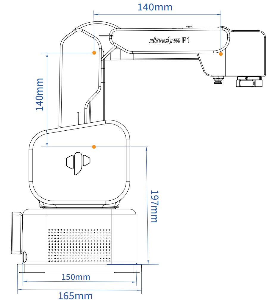
This chapter uses millimeters as distance units and degrees as angle units.
2.1 Product Dimensions
2.2 Joint Range of Motion
Hardware Limits
| Joint | Range |
|---|---|
| J1 | -168° ~ +168° |
| J2 | -25° ~ +90° |
| J3 | +85° ~ +205° |
| J4 | -180° ~ +180° |
Software Limits
| Joint | Range |
|---|---|
| J1 | -158° ~ +158° |
| J2 | -18° ~ +85° |
| J3 | +89° ~ +190° |
| J4 | -179° ~ +179° |
2.3 Maximum Joint Speed
| Joint | Maximum Speed |
|---|---|
| J1 | 180°/s |
| J2 | 120°/s |
| J3 | 130°/s |
| J4 | 180°/s |
3. Base Interface Description
3.1 Base Front View:
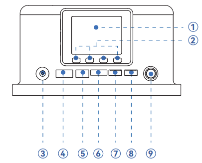
- ➀ MiniRobot Control Screen
- ➁ MiniRobot Button
- ➂ 12V Power: Connect the power adapter.
- ➃ Motor Interface: For connecting and controlling motors.
- ➄ Digital Limit Input: Dedicated input for PNP three-wire photoelectric/proximity sensors.
- ➅ 3.3V-I/O: Provides 3.3V power and digital signal interface.
- ➆ I²C Grove: For connecting I²C communication sensors or modules.
- ➇ PWM Grove: For connecting devices requiring PWM signals, such as servos.
- ➈ Power Switch: Press to lock (power on), press again to release (power off).
3.2 Base Side View:
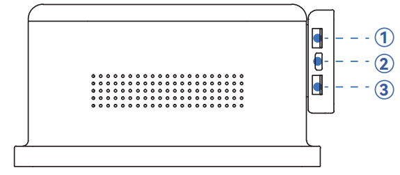
- ➀ RS485 Grove: Industrial serial communication, strong anti-interference, long distance.
- ➁ Type-C Interface: Program flashing and communication.
- ➂ UART Grove: Serial communication, connect serial devices.
3.3 End-Effector Interface Description
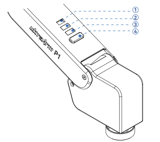
- ➀ Servo Interface: Provides power and control signals for end servo-type actuators (e.g., pneumatic grippers).
- ➁ Grove: Supports 5V digital logic level input.
- ➂ Grove: Provides 5V digital logic level output.
- Tool Button: Used for functional interaction in robotic applications, supports customizable button functions.
4. Cartesian Coordinate
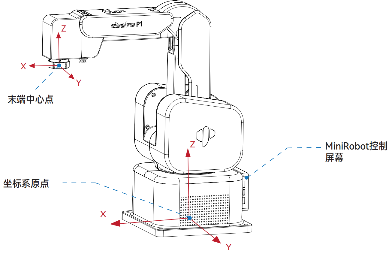
- The definitions of each coordinate system are shown in the table below:
| Coordinate System | Definition |
|---|---|
| End Coordinate System | - Origin: Center point of the end quick-connect lock head horizontal plane (marked as: End Center Point in the diagram). - X-axis: When the robotic arm is at joint zero position, facing the base switch, horizontally forward. - Y-axis: When the robotic arm is at joint zero position, facing the base switch, horizontally to the left. - Z-axis: When the robotic arm is at joint zero position, facing the base switch, vertically upward. |
| Base Coordinate System | - Origin: Center point of the base bottom surface (marked as: Coordinate System Origin in the diagram). - X-axis: Facing the base switch, horizontally forward. - Y-axis: Facing the base switch, horizontally to the left. - Z-axis: Vertically upward. |
5. Joint Coordinate System
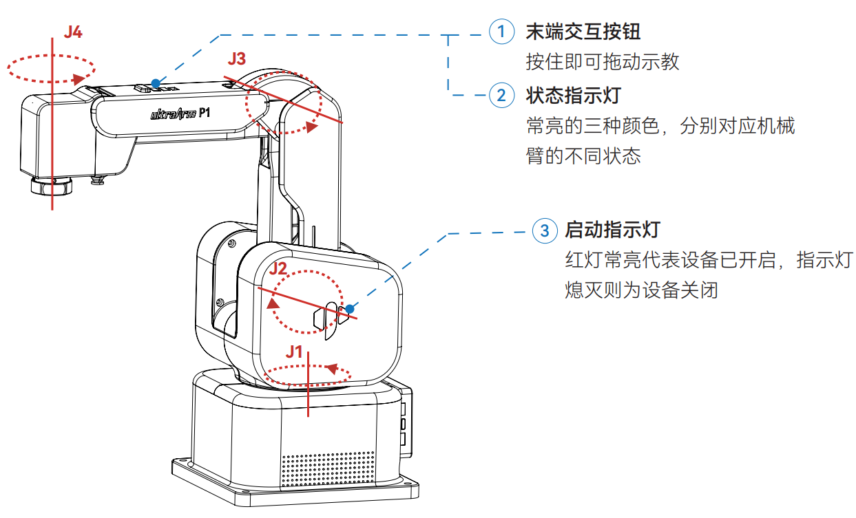
| Color | Description |
|---|---|
| Green | Normal program execution |
| Blue | Kinematics abnormality |
| Red | System error |
6. Working Range
6.1 Workspace Diagram
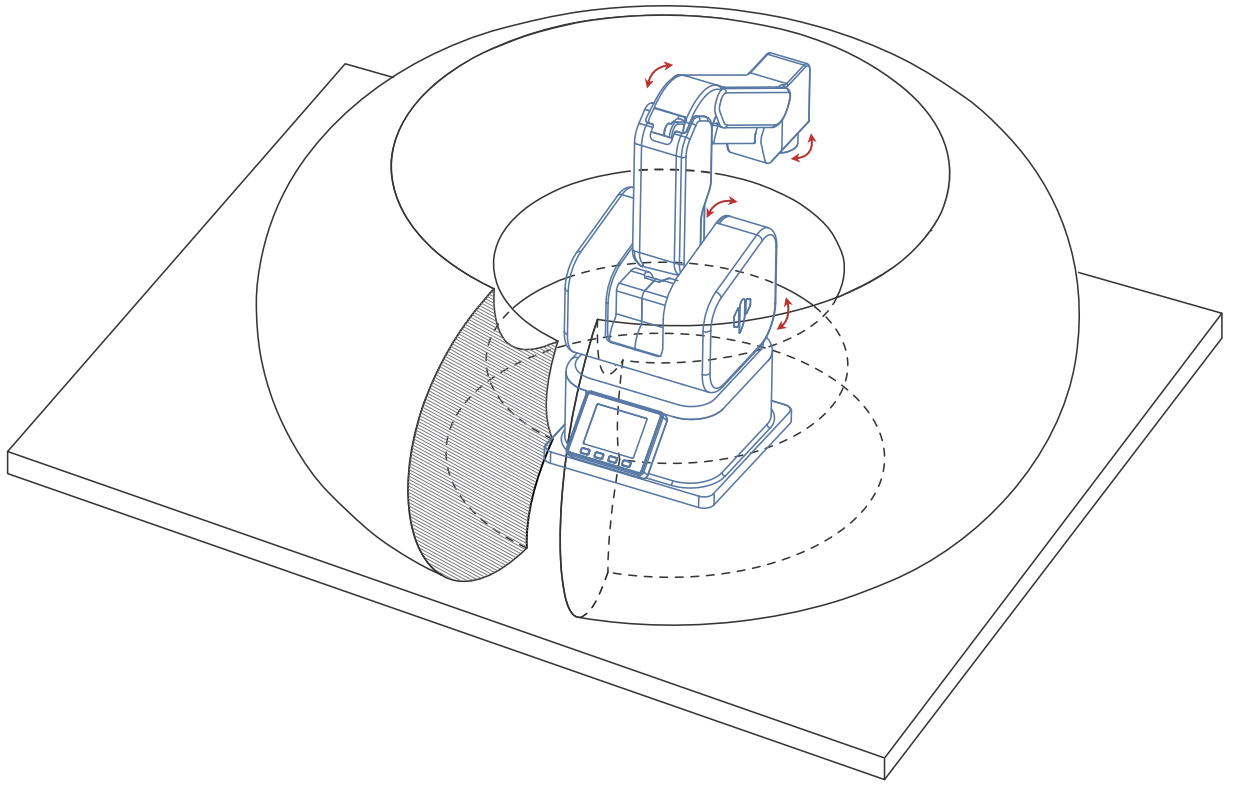
Diagram Description: The annular area in the figure defines the 3D workspace of the robotic arm, which is the set of all spatial points that the end effector can reach; the red arrows in the figure define the movement directions of each joint of the robotic arm.
6.2 Plane Range
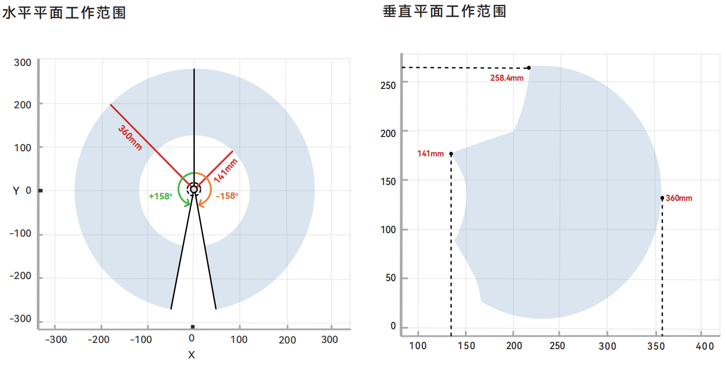
- J1 Motion Range: +/- 158 deg
- Maximum Working Radius: 360 mm
- Minimum Working Radius: 141 mm
- Maximum Working Height: 258.4 mm