Configuration Center
1 Interface Introduction
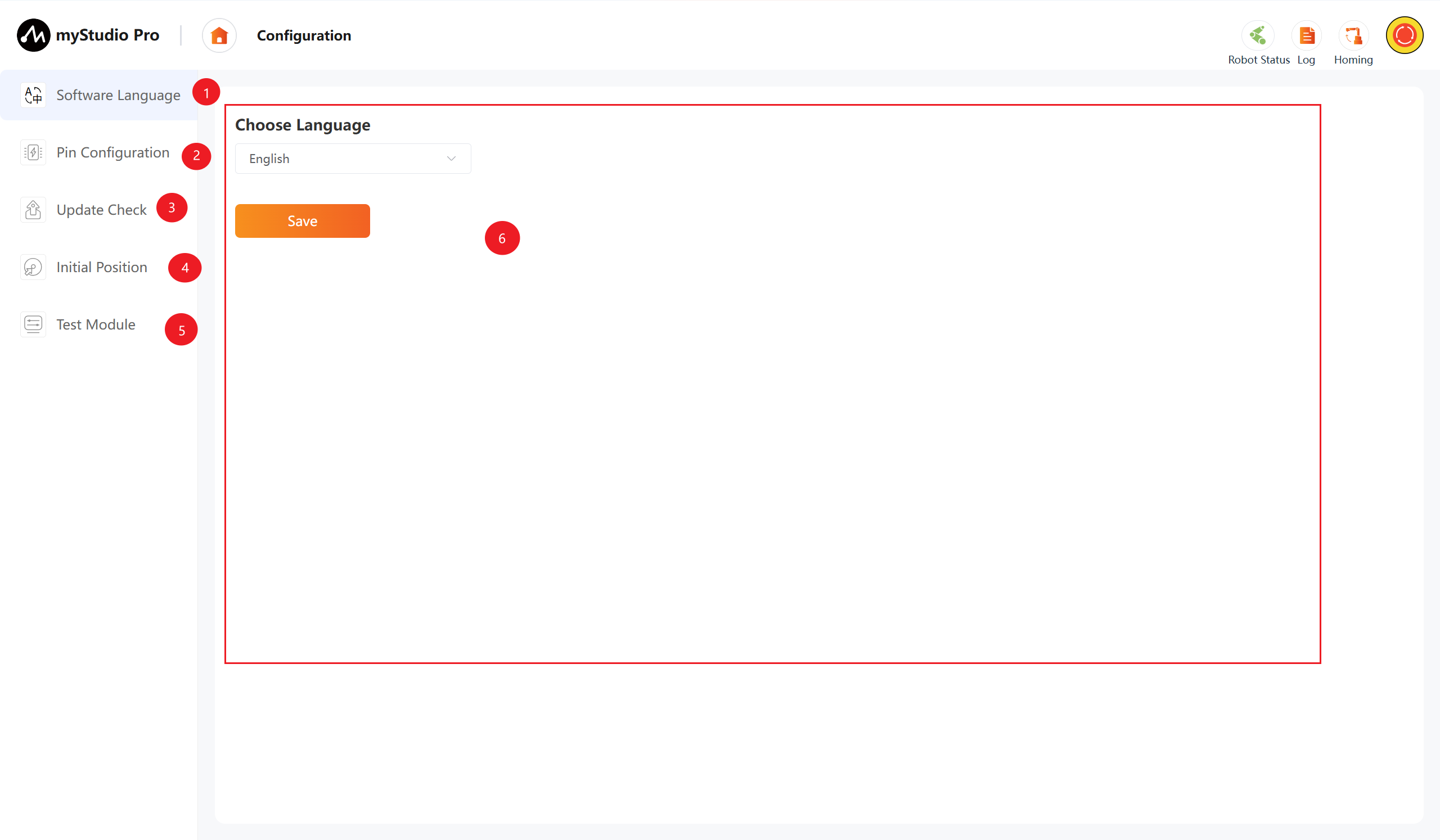
| No. | Description |
|---|---|
| 1 | Software Language Module: used for setting the software display language |
| 2 | Pin Configuration Module: configures base and end tool IO interfaces |
| 3 | Update Check Module: downloads and upgrades software and firmware |
| 4 | Initial Position Module: views and switches initial and packing postures |
| 5 | Test Module: checks communication, firmware version, and servo status |
| 6 | Module Content Display Area: shows the current module's operation interface |
2 Software Language
Click the Software Language icon button to enter the language settings page. Language selection supports 中文 and English.
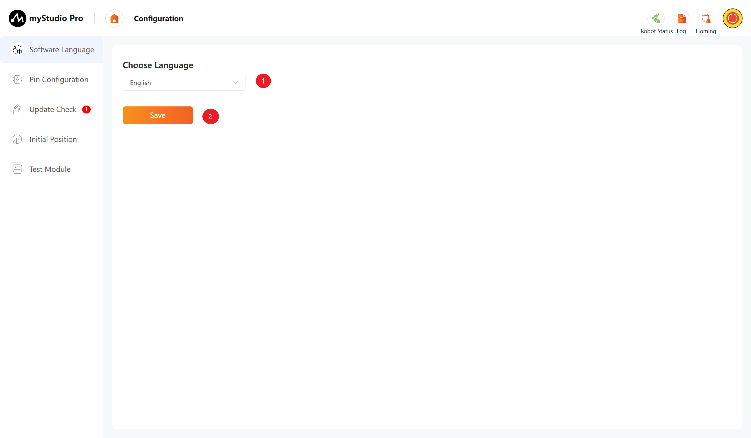
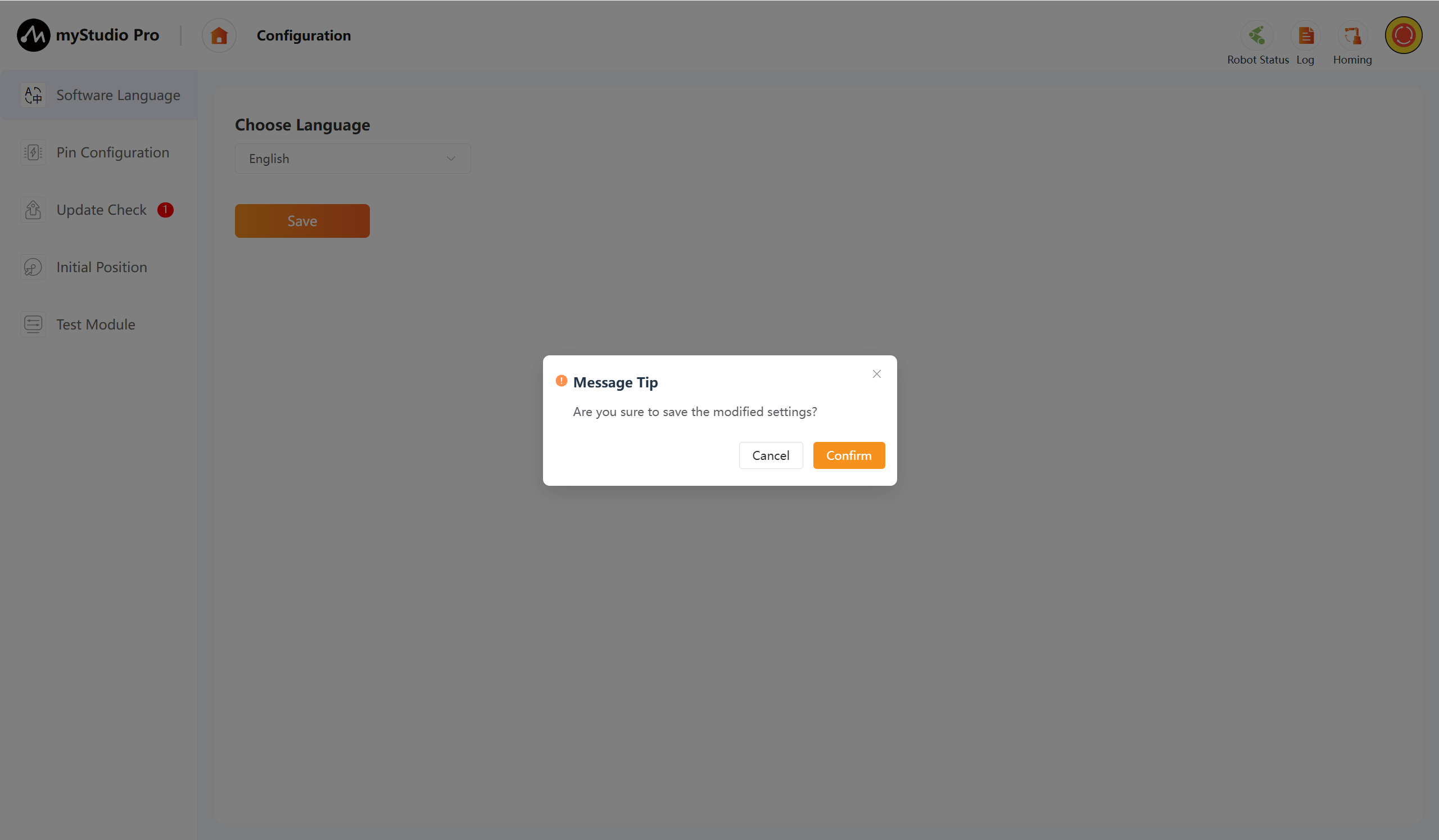
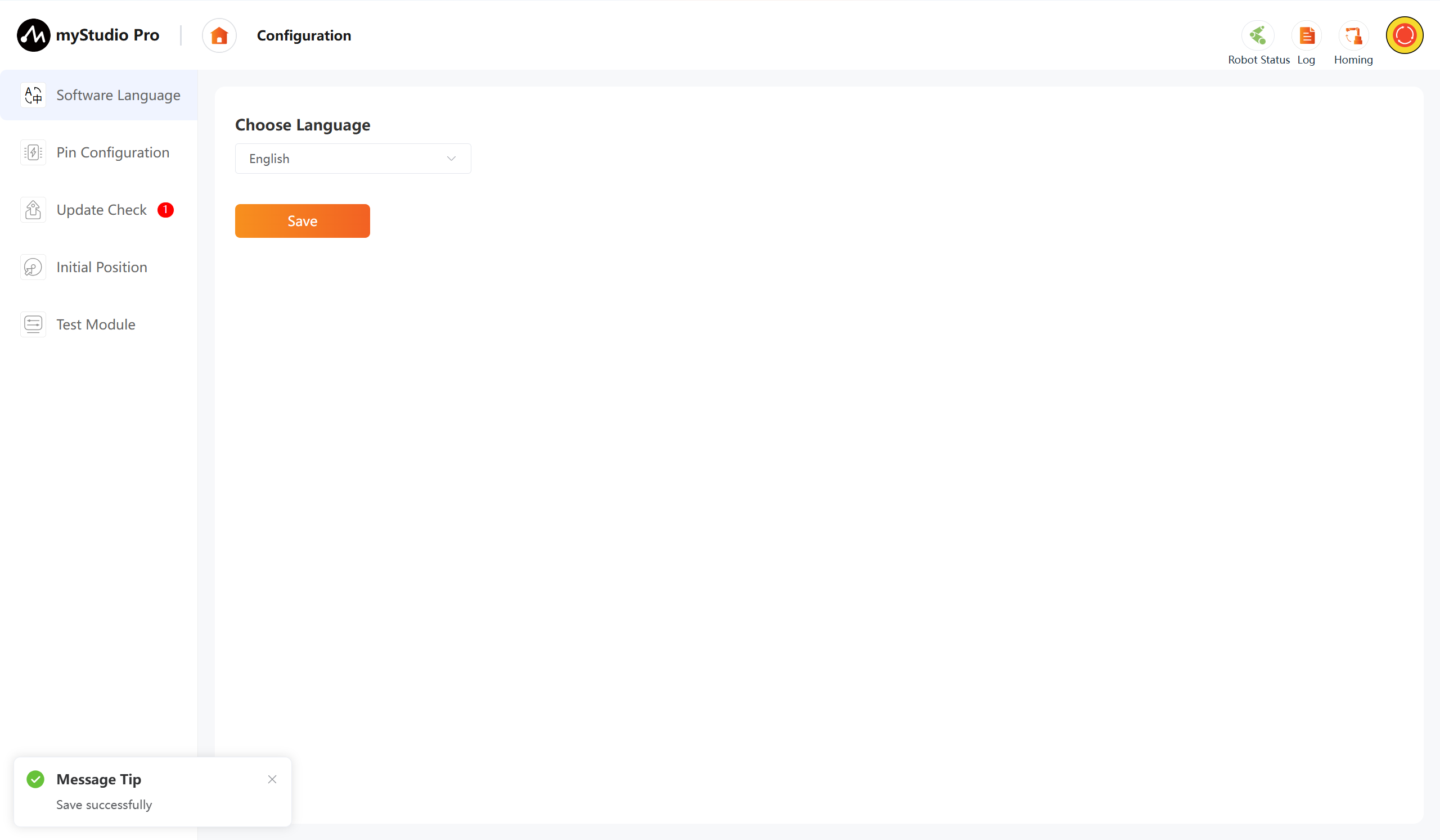
After selecting the corresponding language, click the Save button. A secondary confirmation prompt window will appear. Click "Confirm" and the language setting will be successfully completed.
3 Pin Configuration
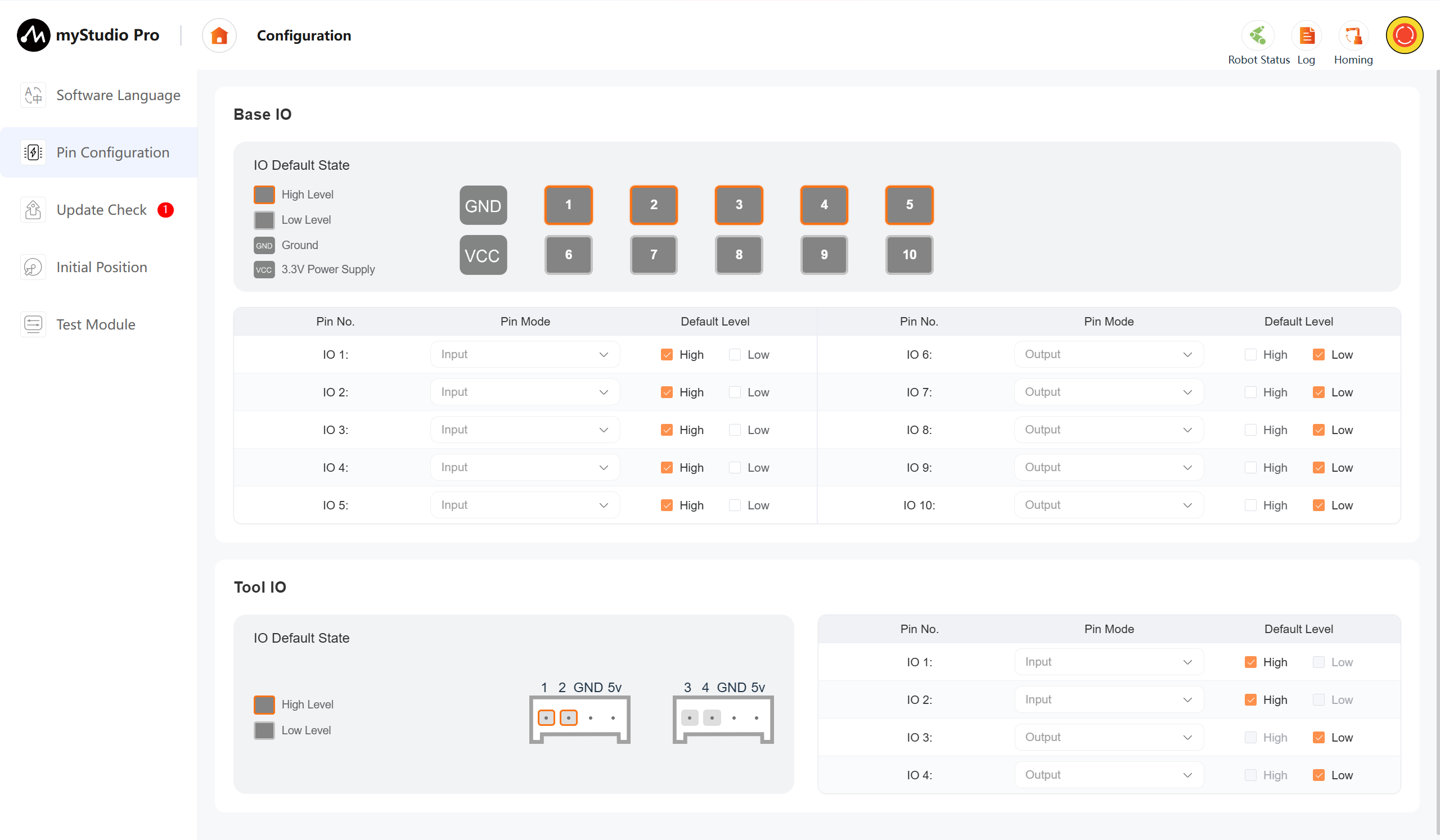
Click the Pin Configuration icon button. This module is used to configure and monitor the digital IO interfaces of the robotic arm base and the end tool. By combining the physical simulation view with the logical configuration table, users can define the signal direction (input/output) and default level status (high level/low level) of the pins.
Default level
Configurable pin default levels: In output mode, the physical level is sent; in input mode, the level state is configured via pull-up/pull-down resistors (used for testing when no external connection is present). By system default, input pins are configured with internal pull-up (high level), and output pins initially output low level.
Pin configuration
Configurable input and output for each IO port (except for IO1 and IO2 of the tool IO, which are fixed as input pins, and IO3 and IO4, which are fixed as output pins)
The pins 1 to 5 on the base are set as input by default; the pins 6 to 10 on the base are set as output by default.
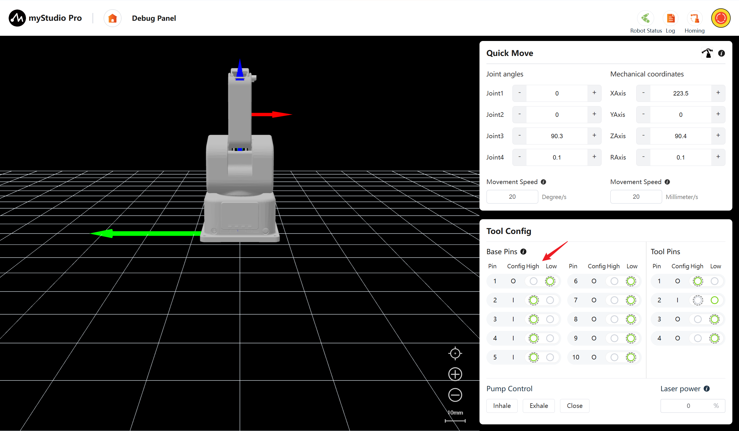
After modifying the configuration of a single pin (input/output mode or default level), the configuration of that pin is updated in real time and synchronized to the corresponding pin configuration item in the Debug Panel
Note: The pin configuration page is dedicated to initializing default levels. Modifications to I/O ports will be synchronized to the Debug Panel in real time. The Debug Panel displays the actual current level status of the pins.
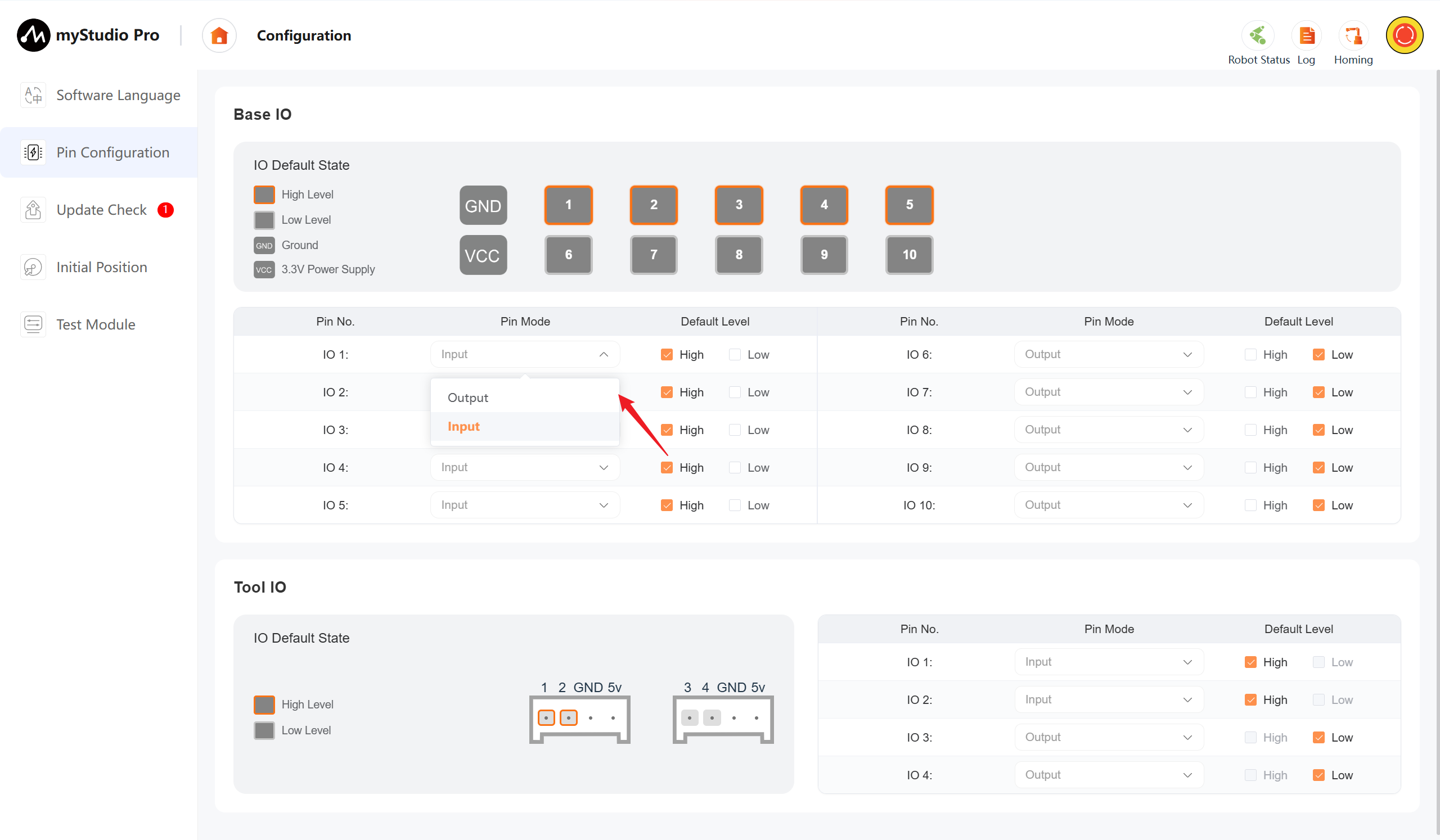
Operate using the bottom IO pin number 1 as an example
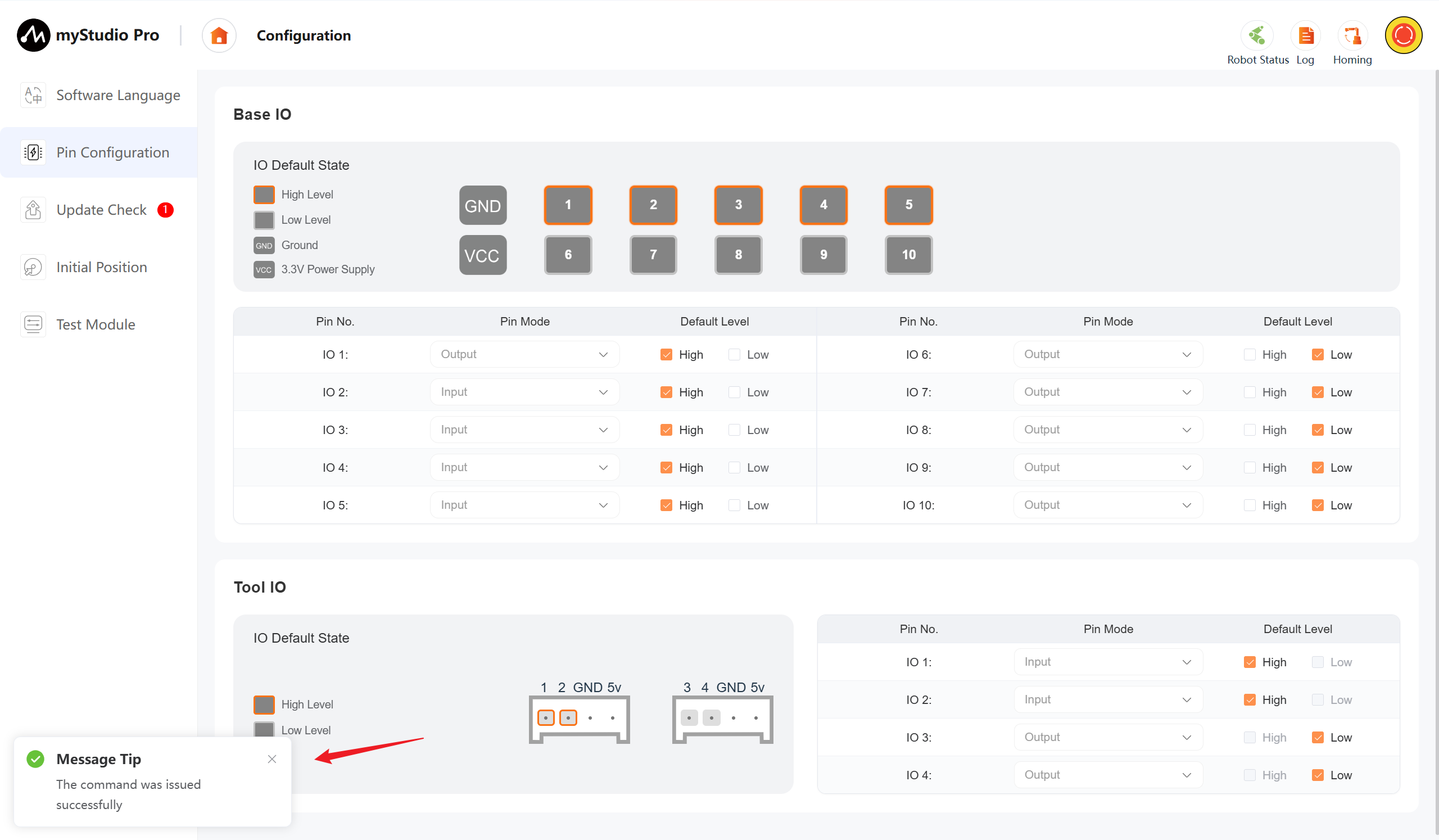
The pin configuration has been changed from input to output. Once the modification is successful, the message 【The Command was issued successfully】 will be returned.
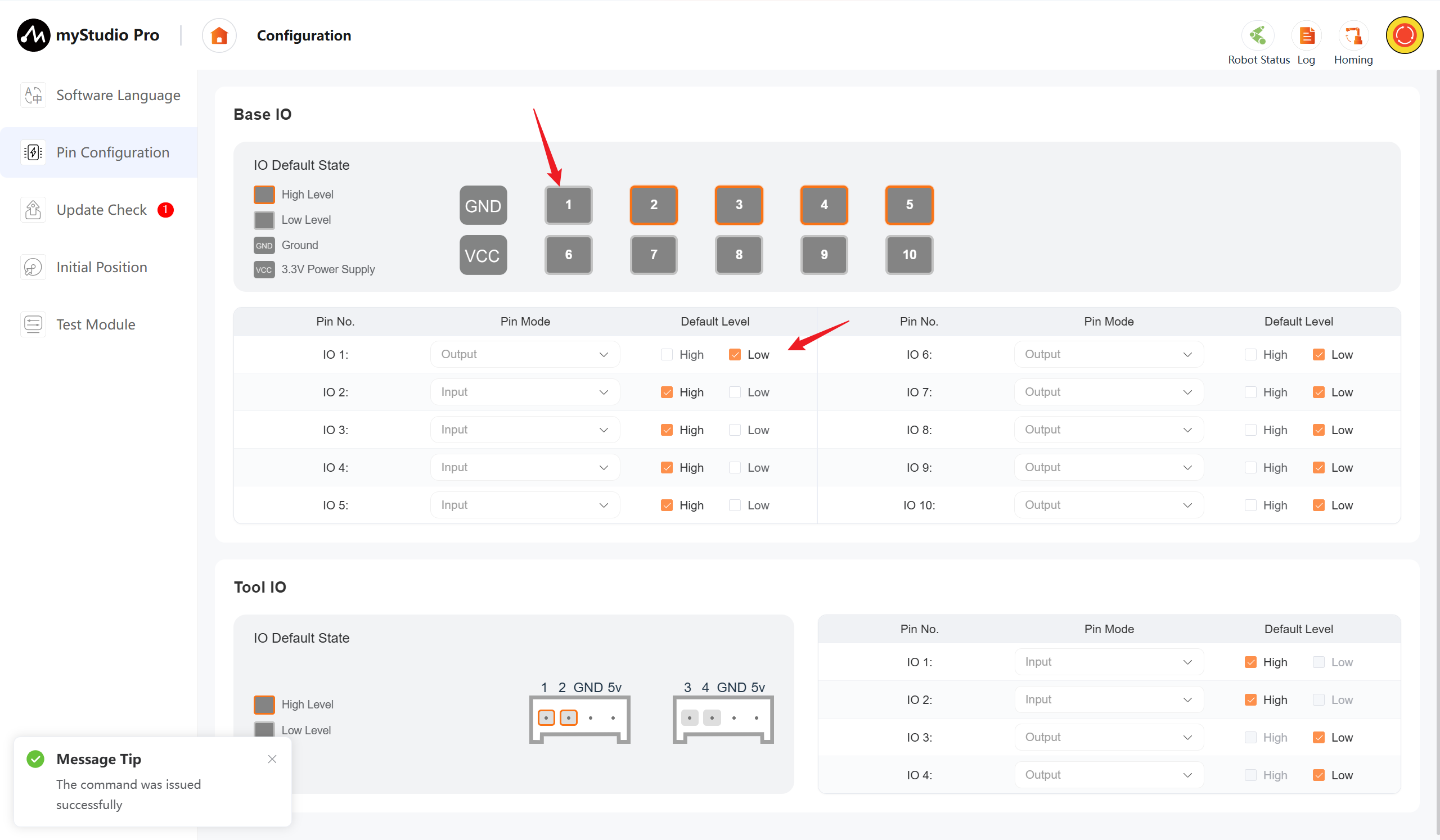
The default level is changed from a high level to a low level. After the modification is successful, the message 【The Command was issued successfully】 will be returned, and the high-level indicator in the default status bar will disappear.
After the modification is completed, go to the debugging panel page to view the modified items. The status has been synchronized.
4 Update Check
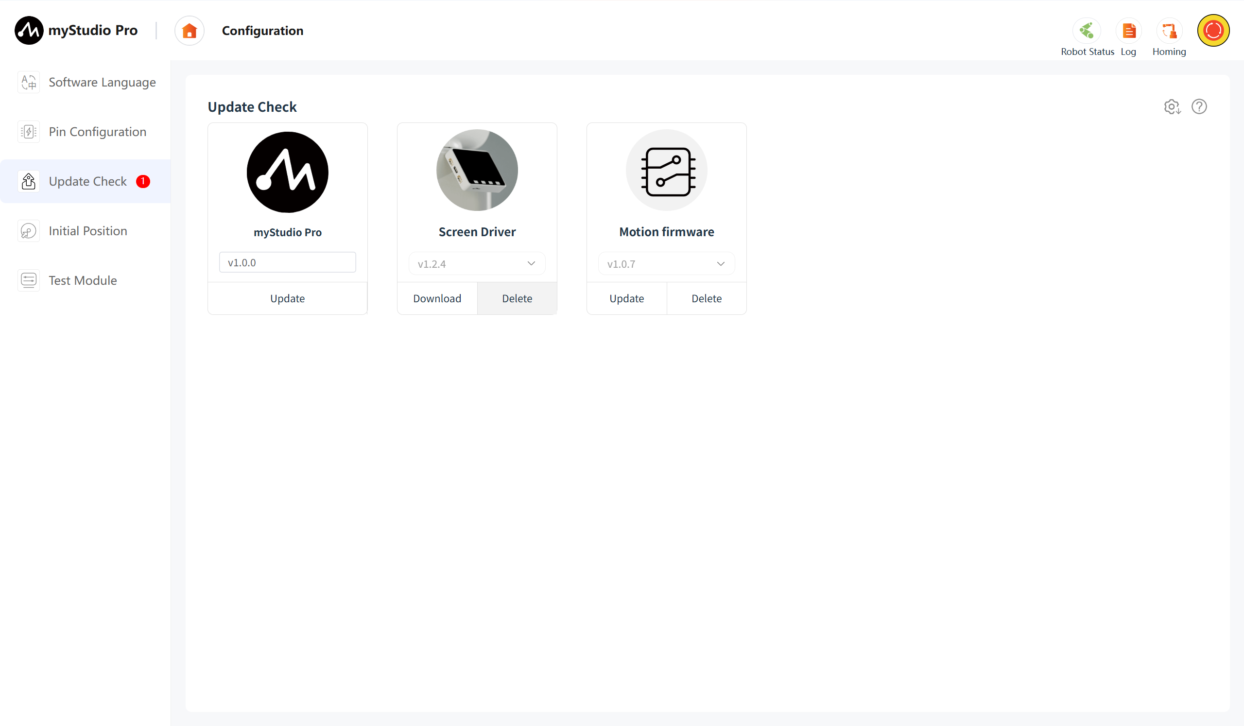
Clicking the Update Check icon will take you to the update status page. This page allows you to download, delete, and upgrade software drivers (myStudio Pro, screen driver, motion firmware).
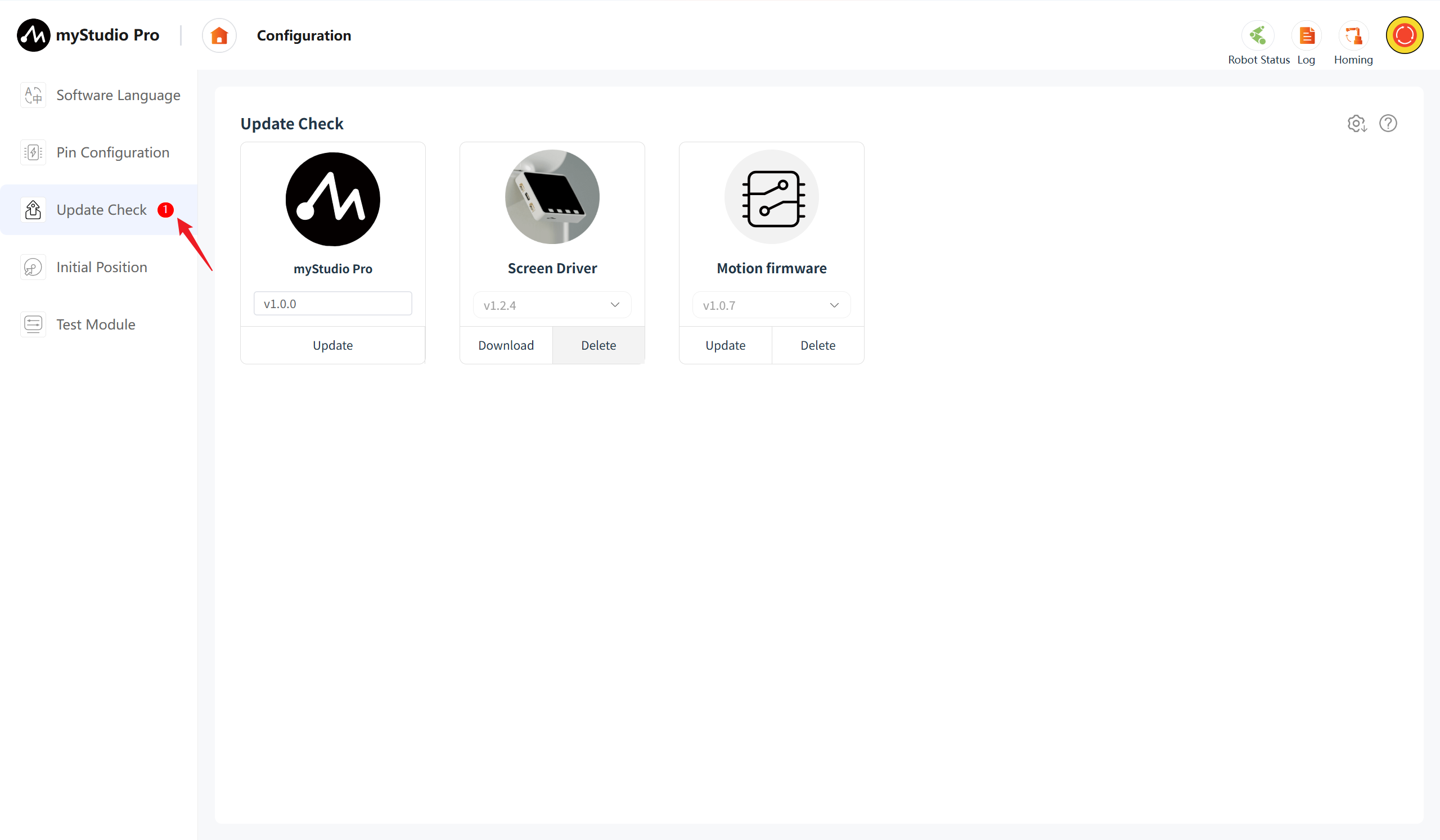
When the software/firmware has the latest version and no upgrade operation has been performed, a red number 1 will be displayed next to the Update Check icon. This indicates that there is a new version pending update. You can then access this page to view the specific upgrade details.
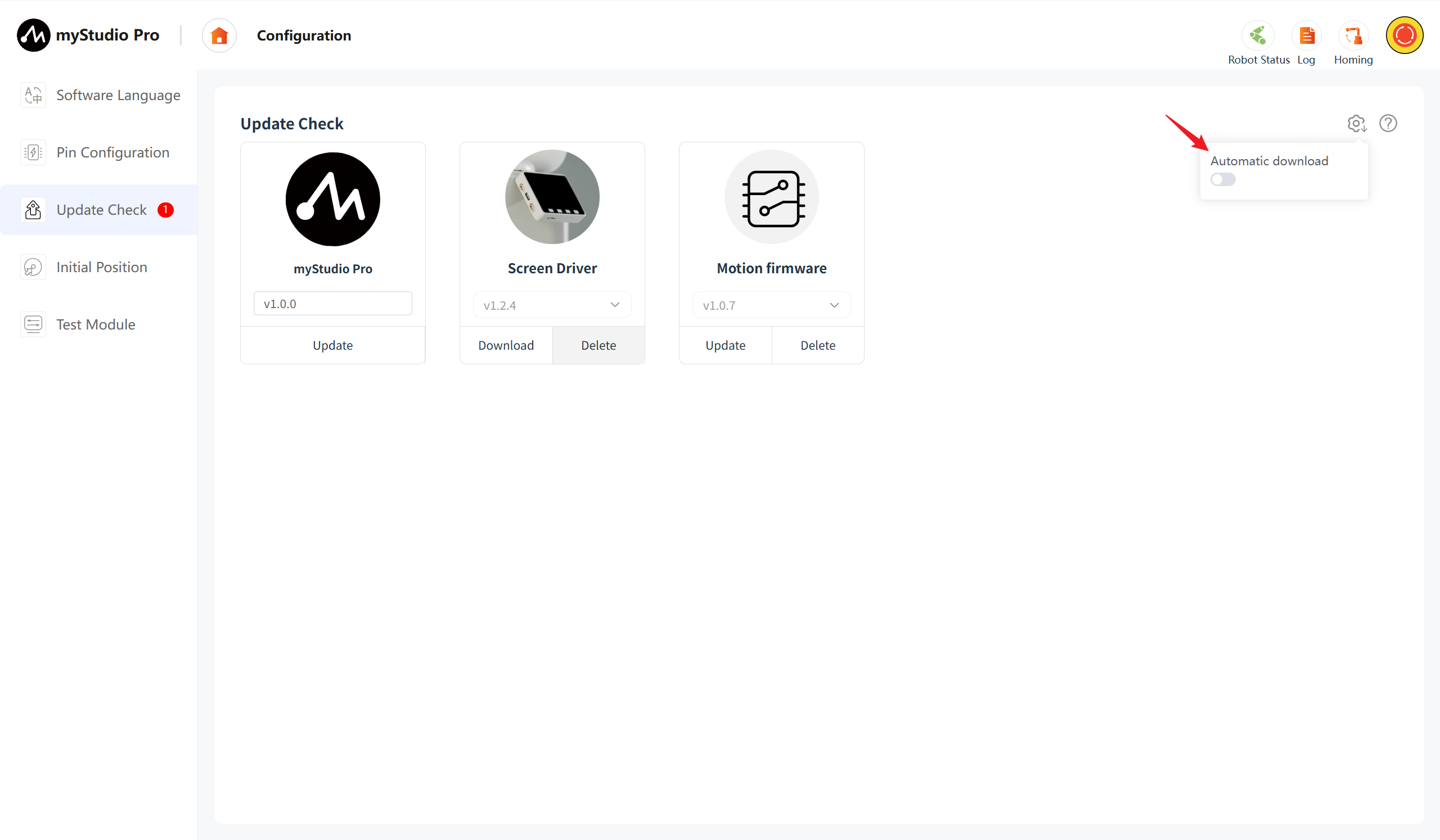
On this page, you can enable the automatic download function for the software or firmware. As the name suggests, the automatic download will silently download the latest version of the software or firmware in the background.
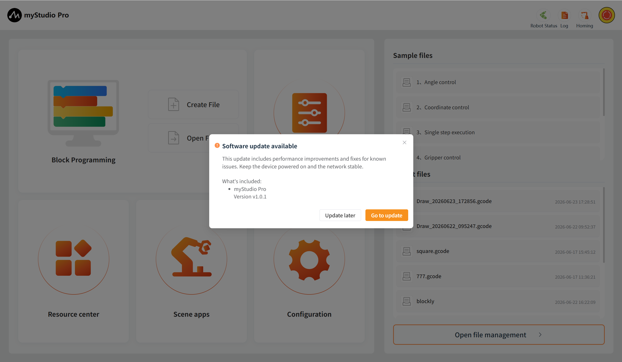
When there is a new version of the software/firmware available, a pop-up window with upgrade information will appear when you enter the main page. Through this pop-up window, you can view the contents of the new version. If you click Update later or close the pop-up window, you will not proceed to the page for checking updates. On the contrary, if you click Go to Update, it will redirect you to the page for checking updates, but you still need to manually update.
myStudio Pro Upgrade
Version Number
By default, the current version of the software is displayed. If the current version is the latest one, it will show Latest; otherwise, it will show Update.
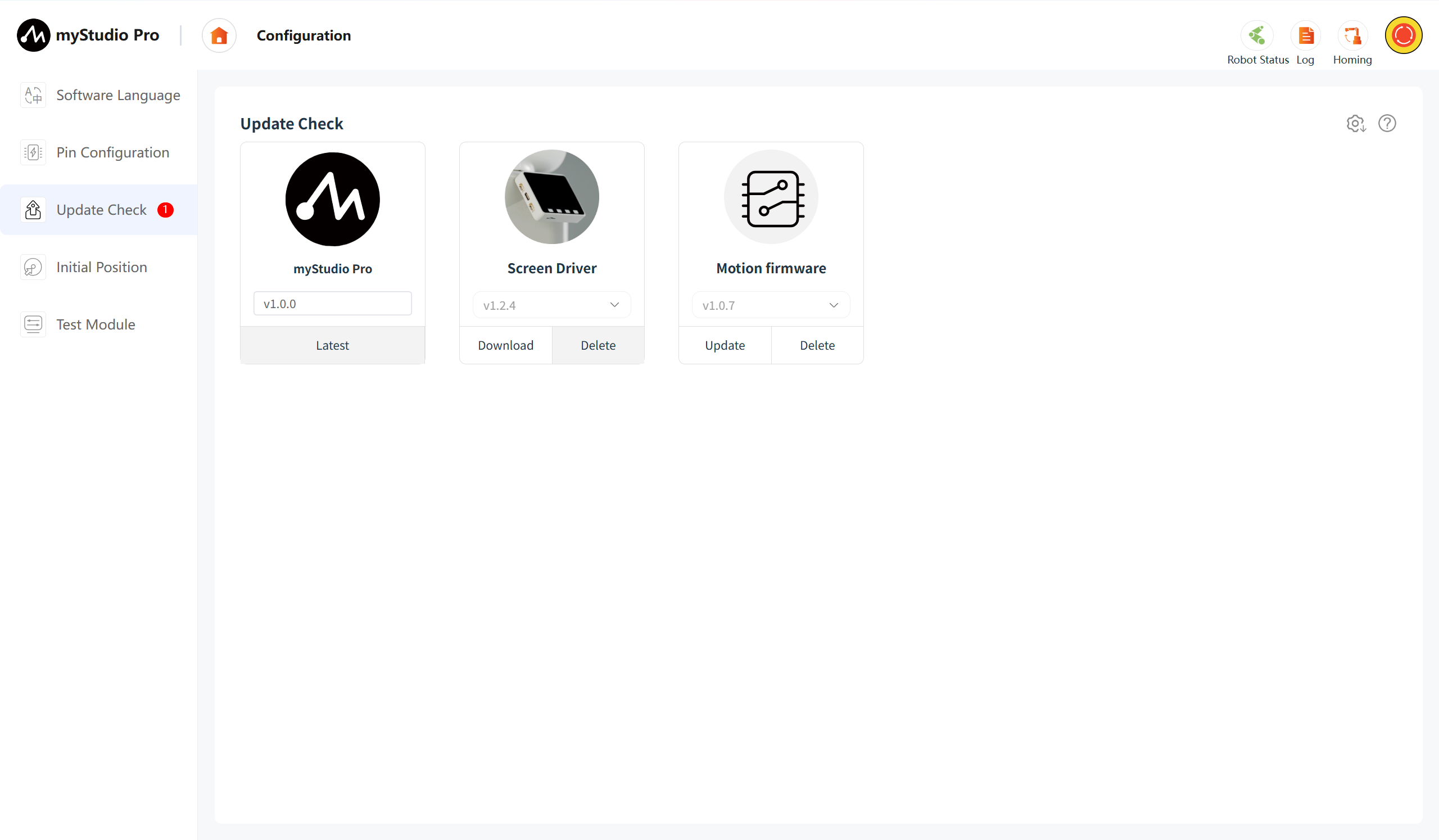
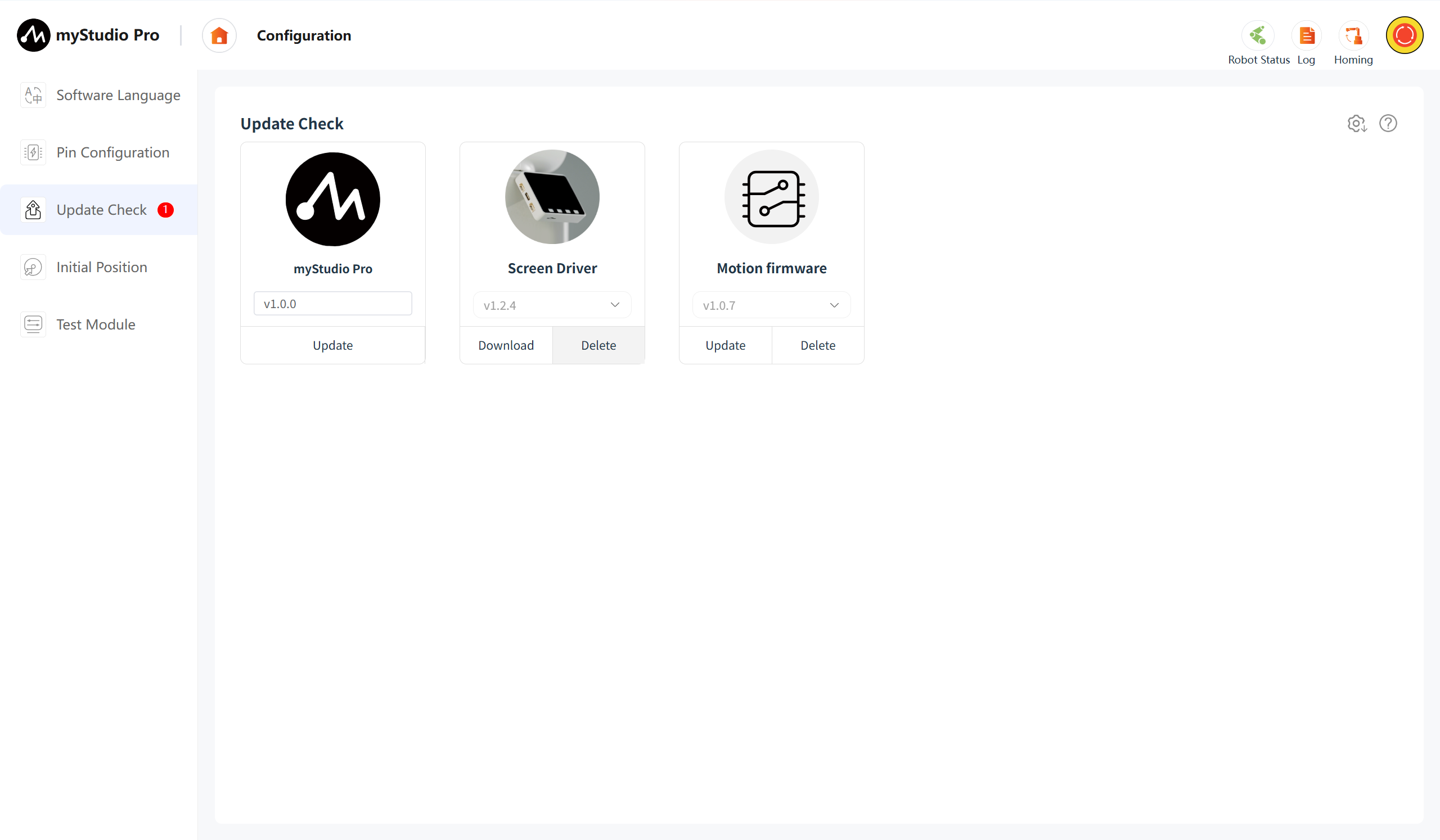
If a new version is detected, clicking the "Update" button will display a version information pop-up window, which includes the latest version, the current version, and the updated contents.
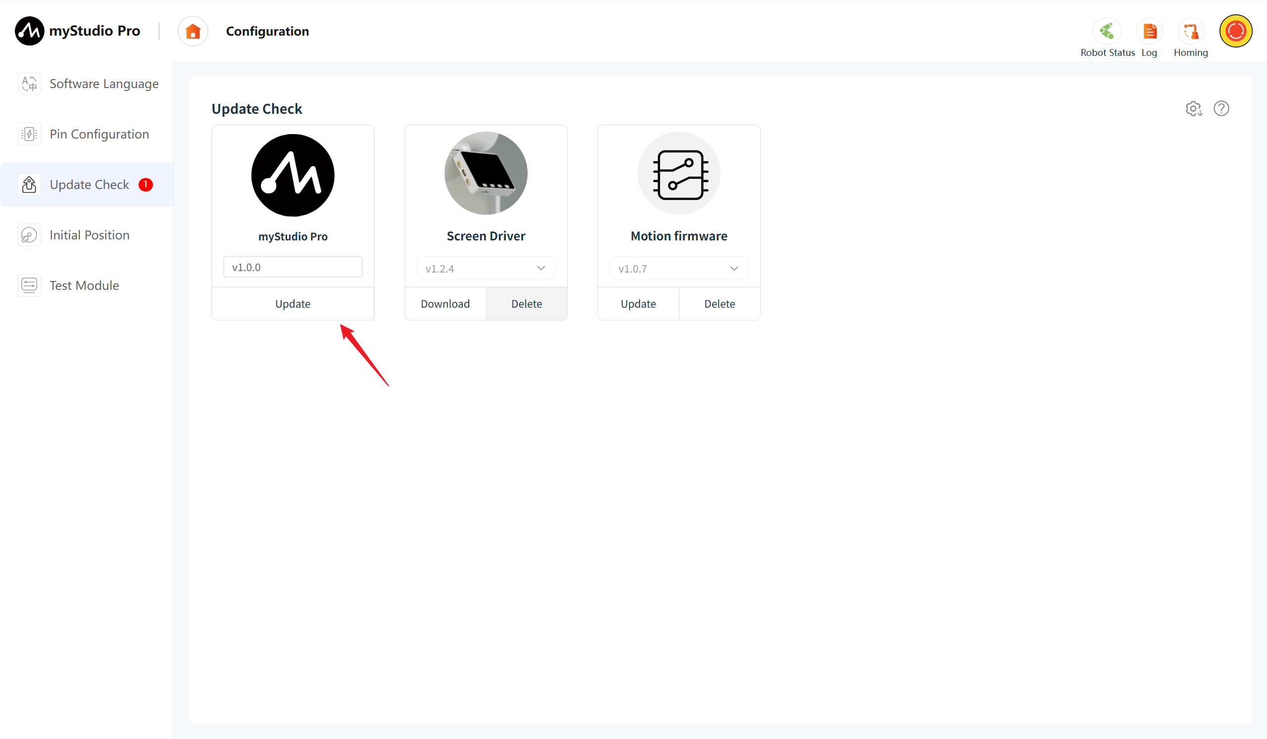
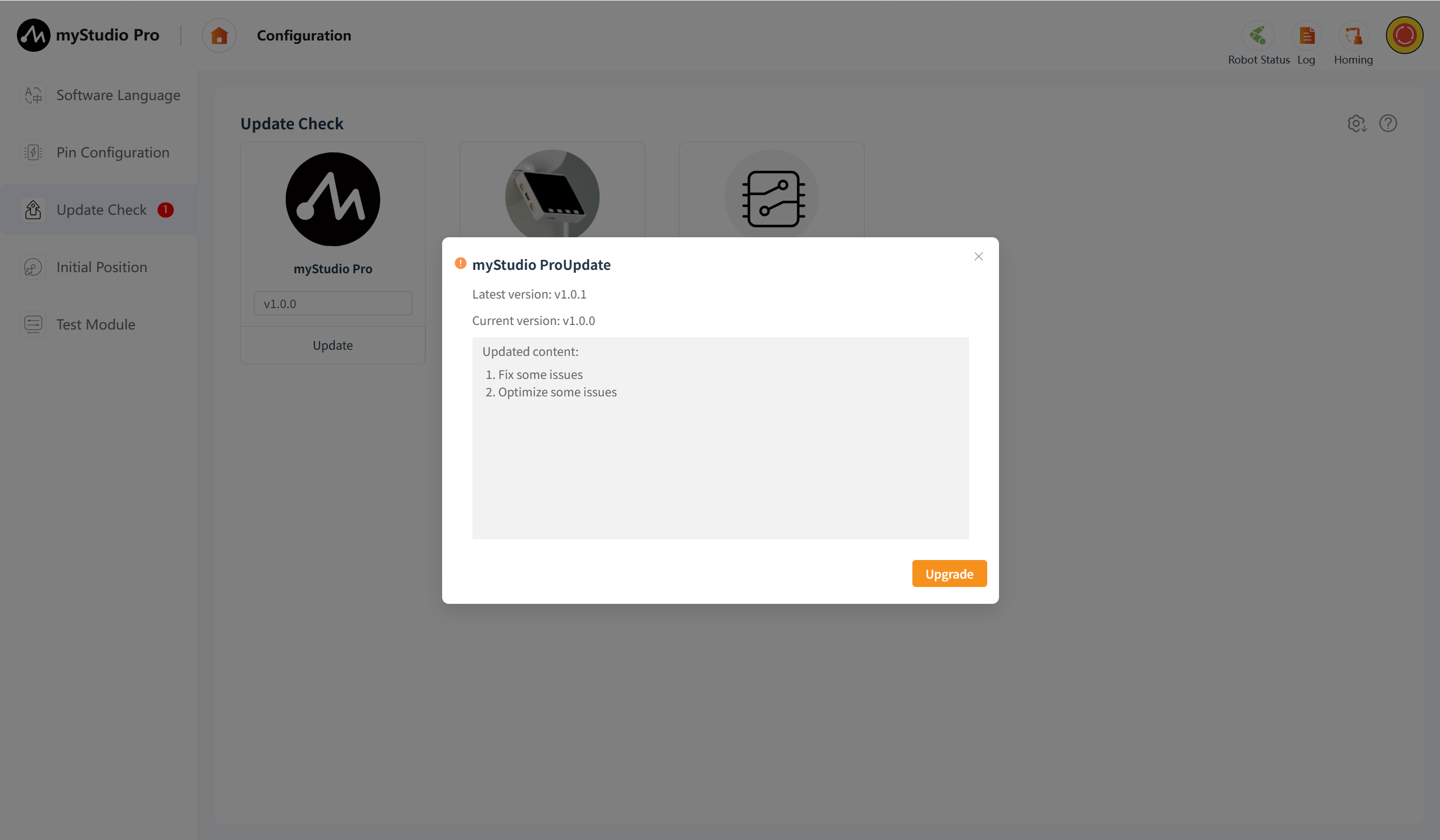
Clicking the "Upgrade" button will initiate the download process of the installation package, and the download progress will be displayed at the same time.
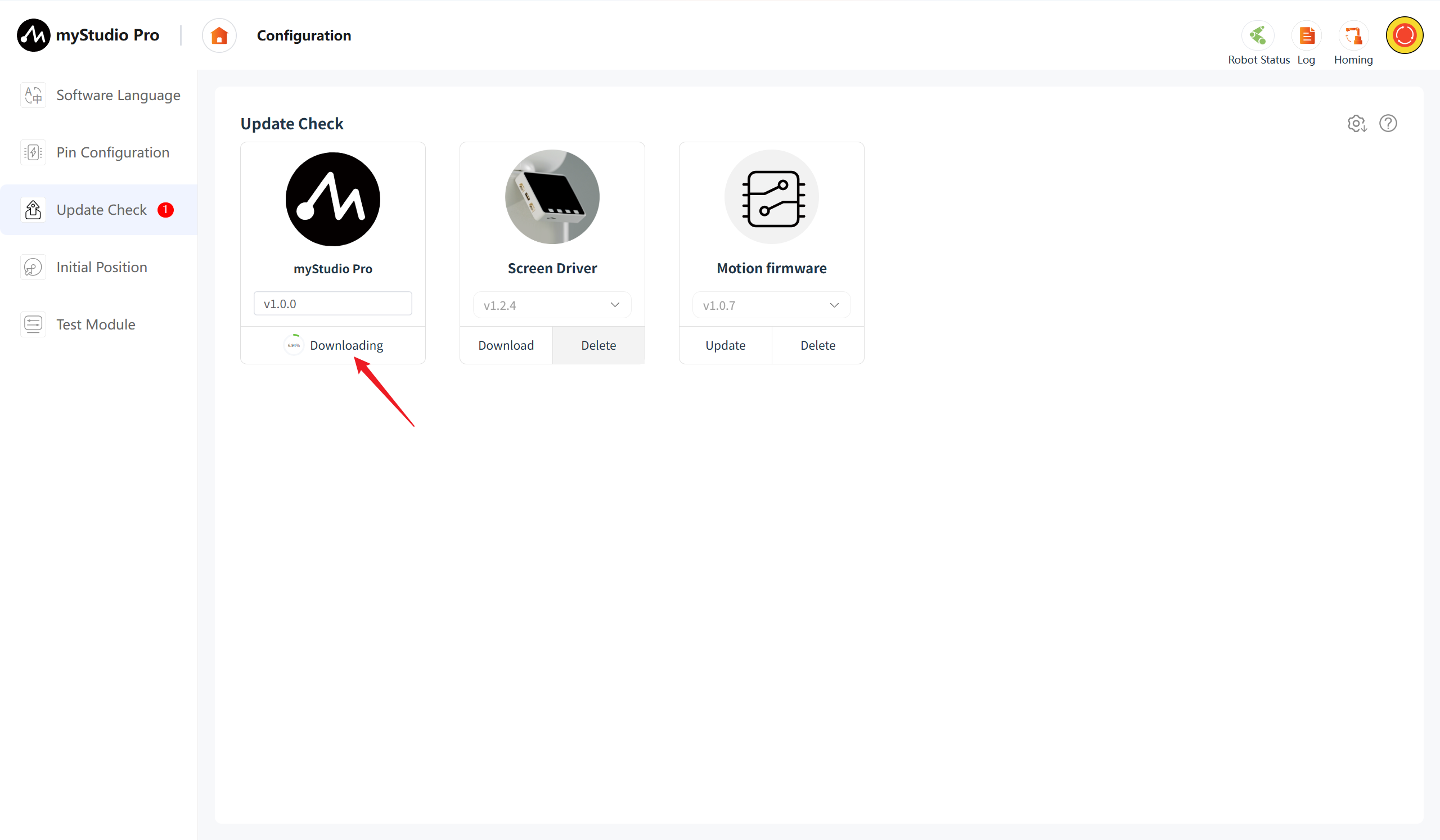
When the installation package is downloaded completely, the "Install" button will be displayed. Clicking on it will allow you to perform the software installation operation.
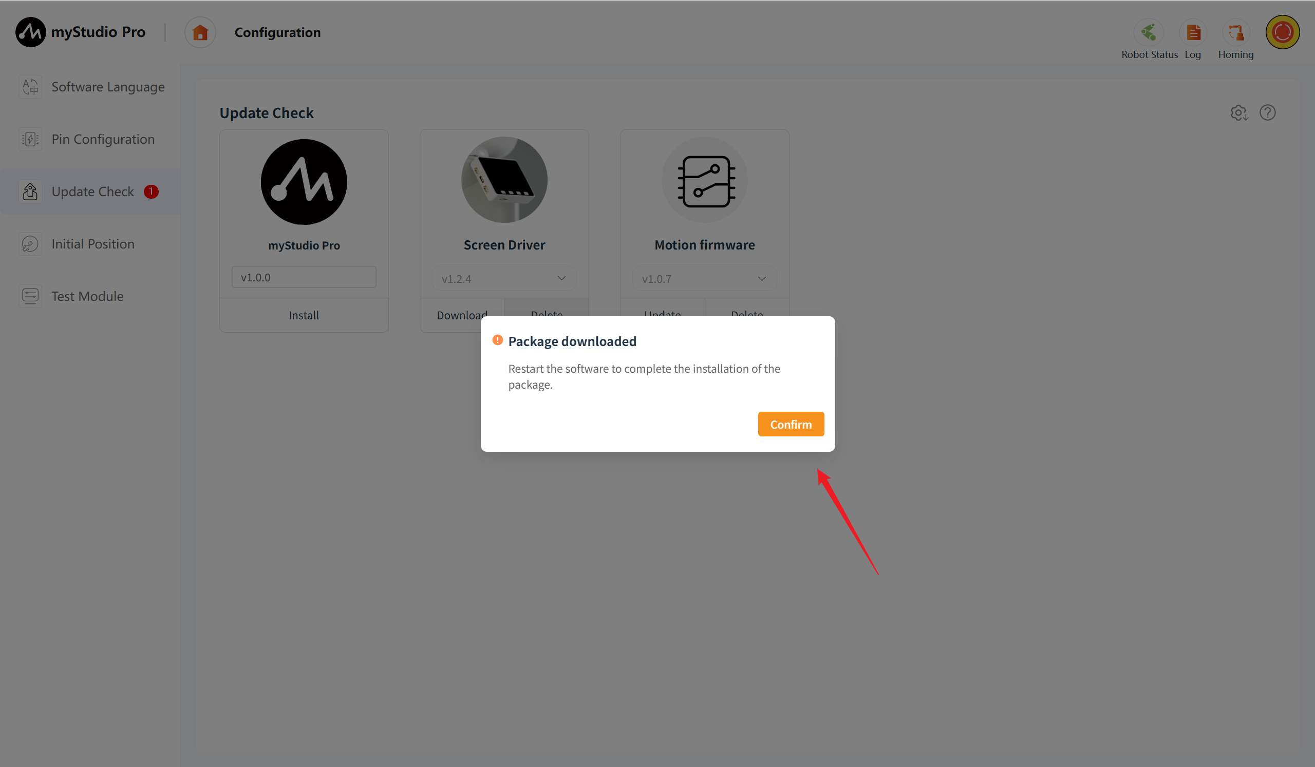
Screen Driver Firmware Upgrade
Version Number
If a new version is detected, it will be displayed; otherwise, the last selected version will be the default display.
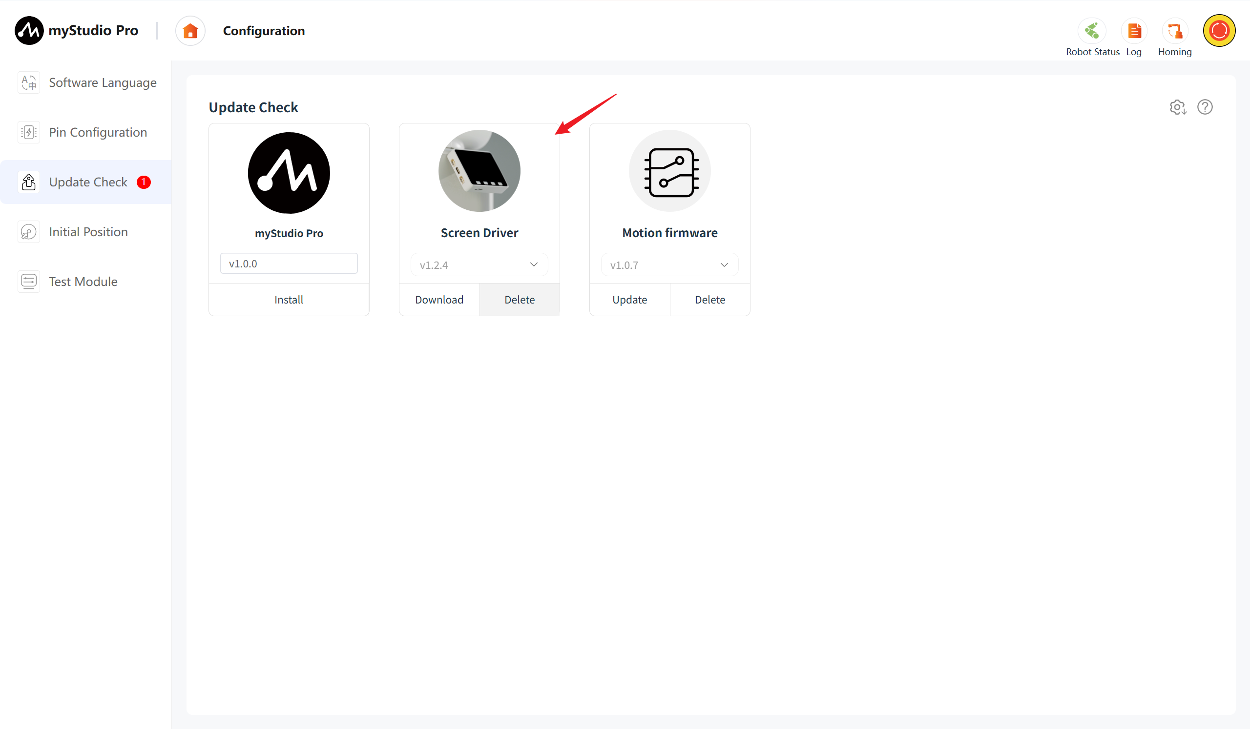
The icon on the right side of the current version is green, the version that has not been downloaded is gray, and the version that has been downloaded but not updated is orange.
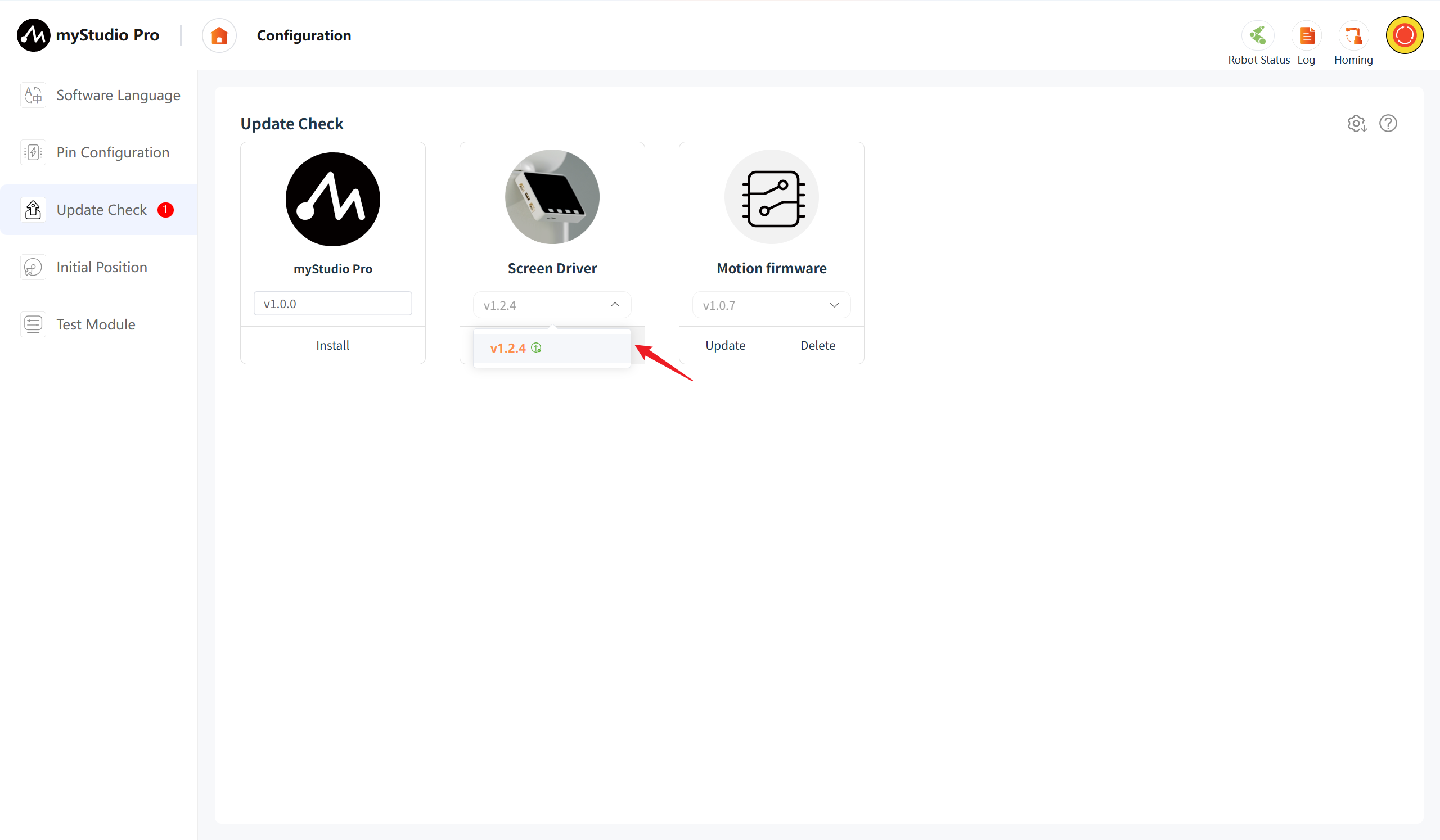
When the version has not been downloaded, the "Delete" button is disabled while the "Download" button is available. Clicking the "Download" button will initiate the download of the version firmware, and a download progress bar will be displayed. After the download is complete, the delete button becomes available and the【Update】button is displayed.
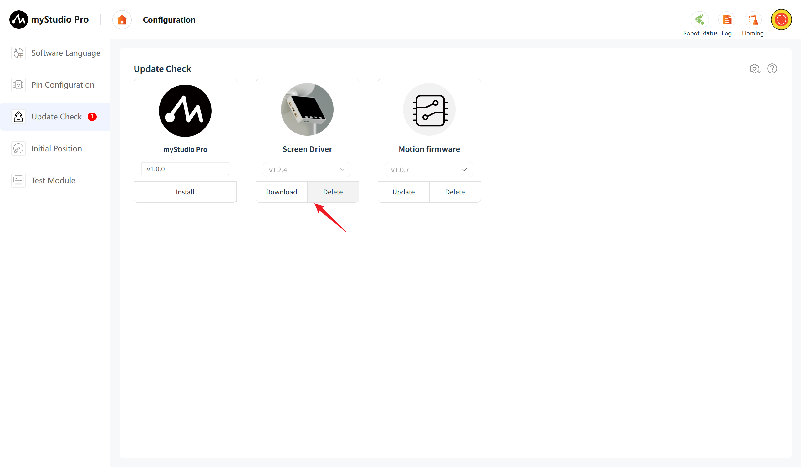
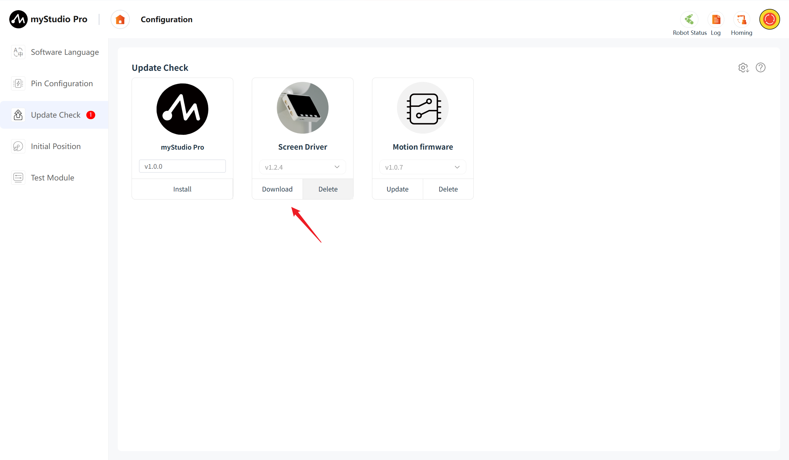
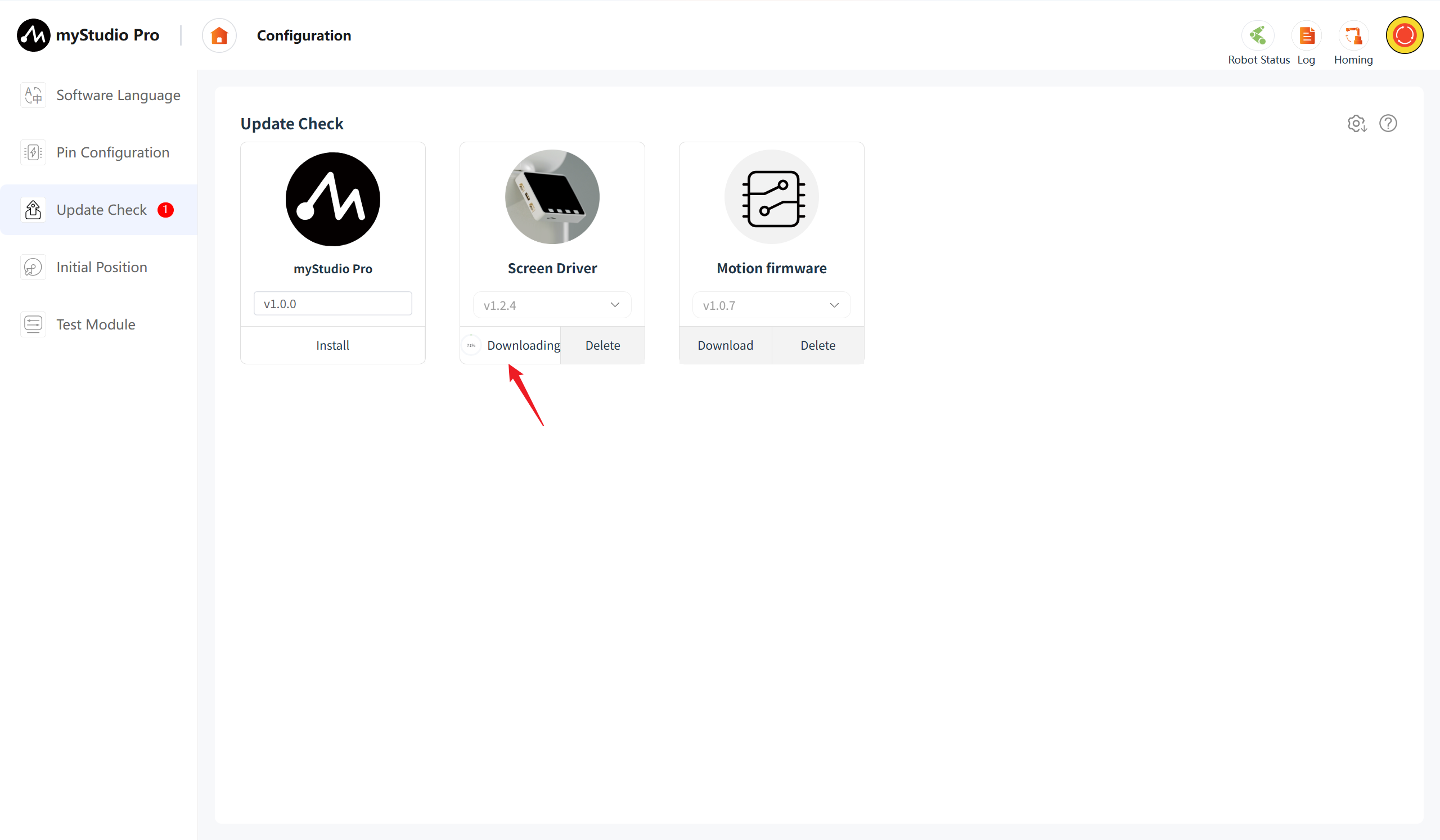
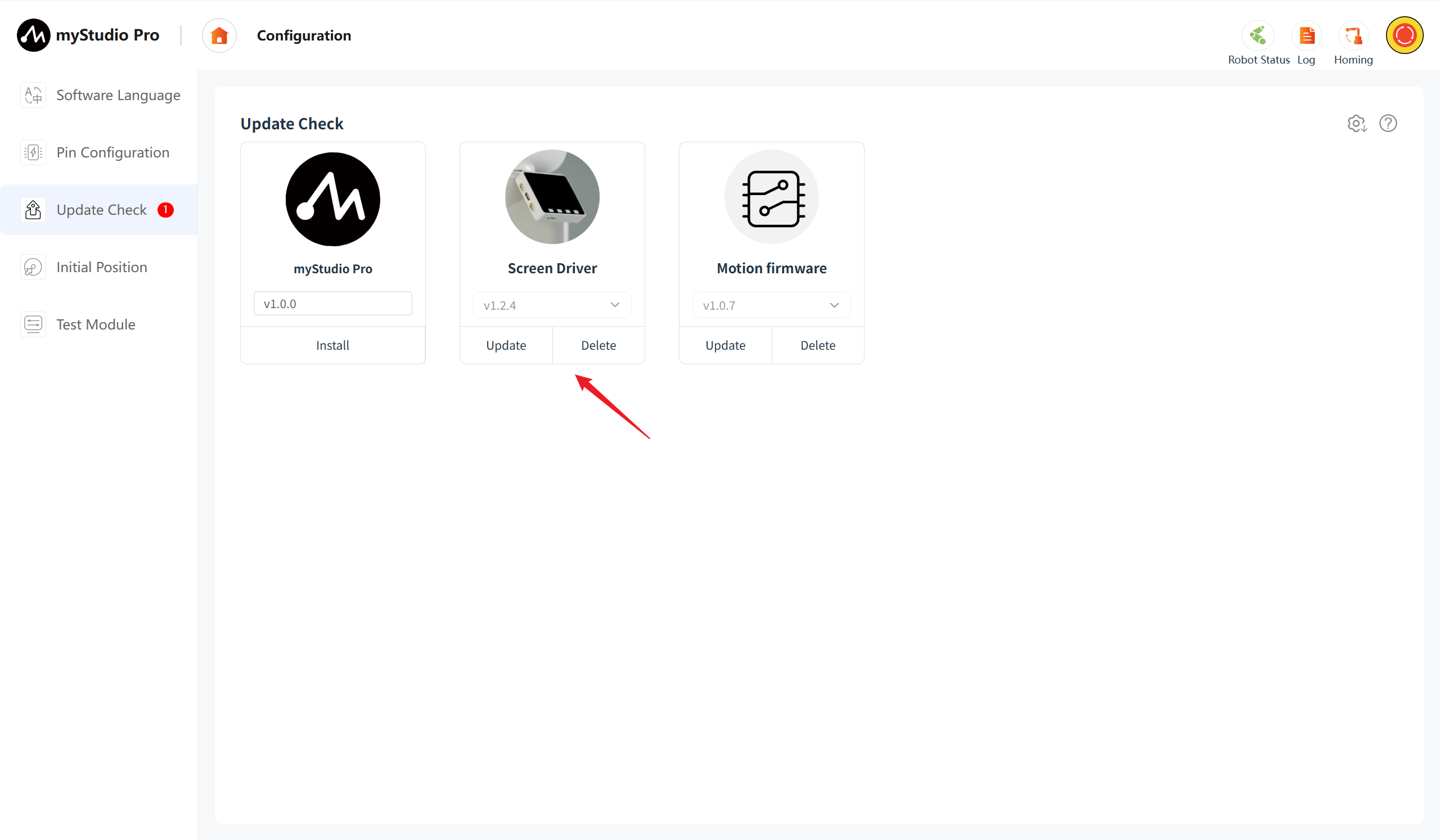
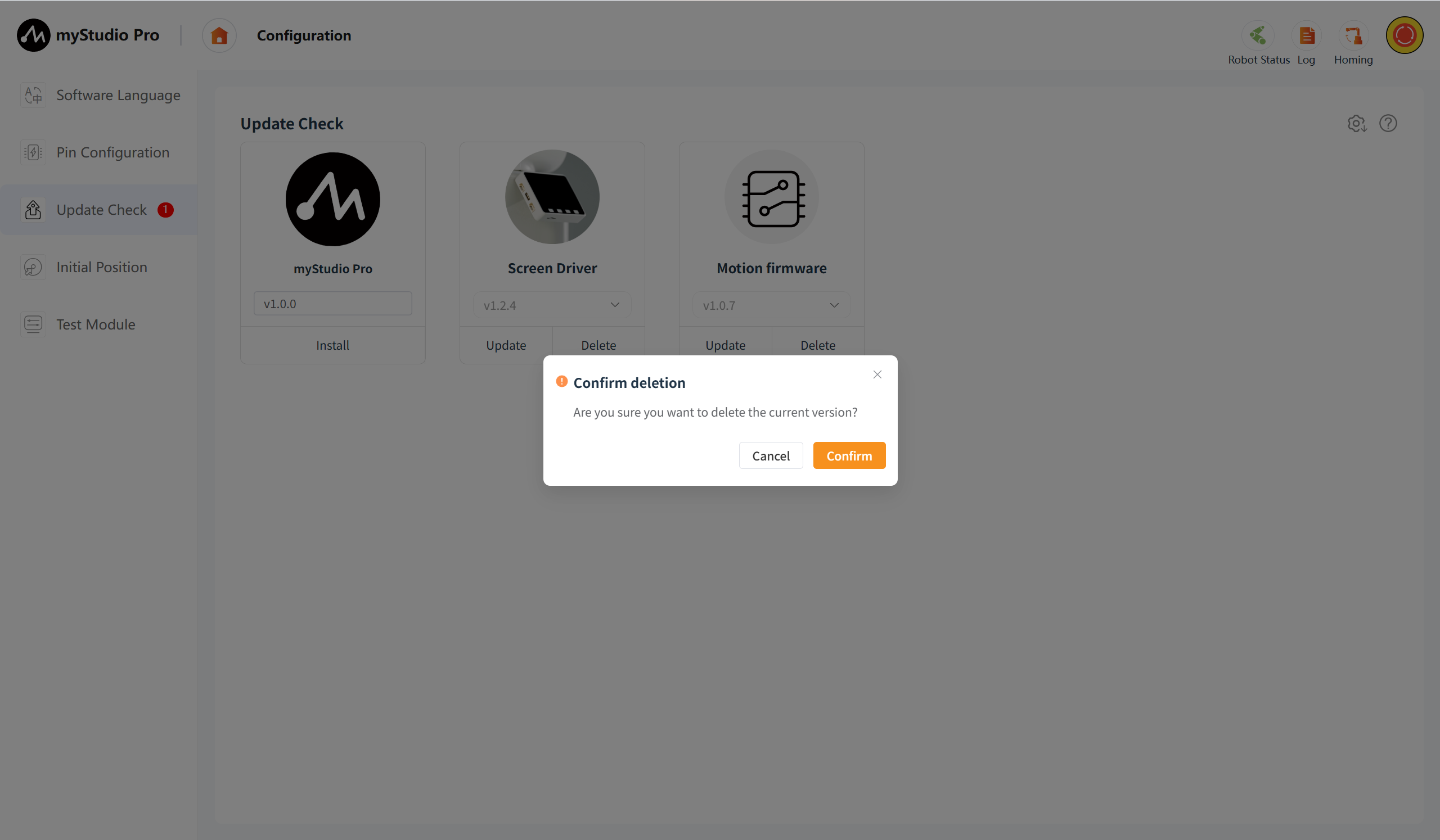
The downloaded firmware can be deleted. Clicking the delete button will bring up a confirmation window for the deletion.
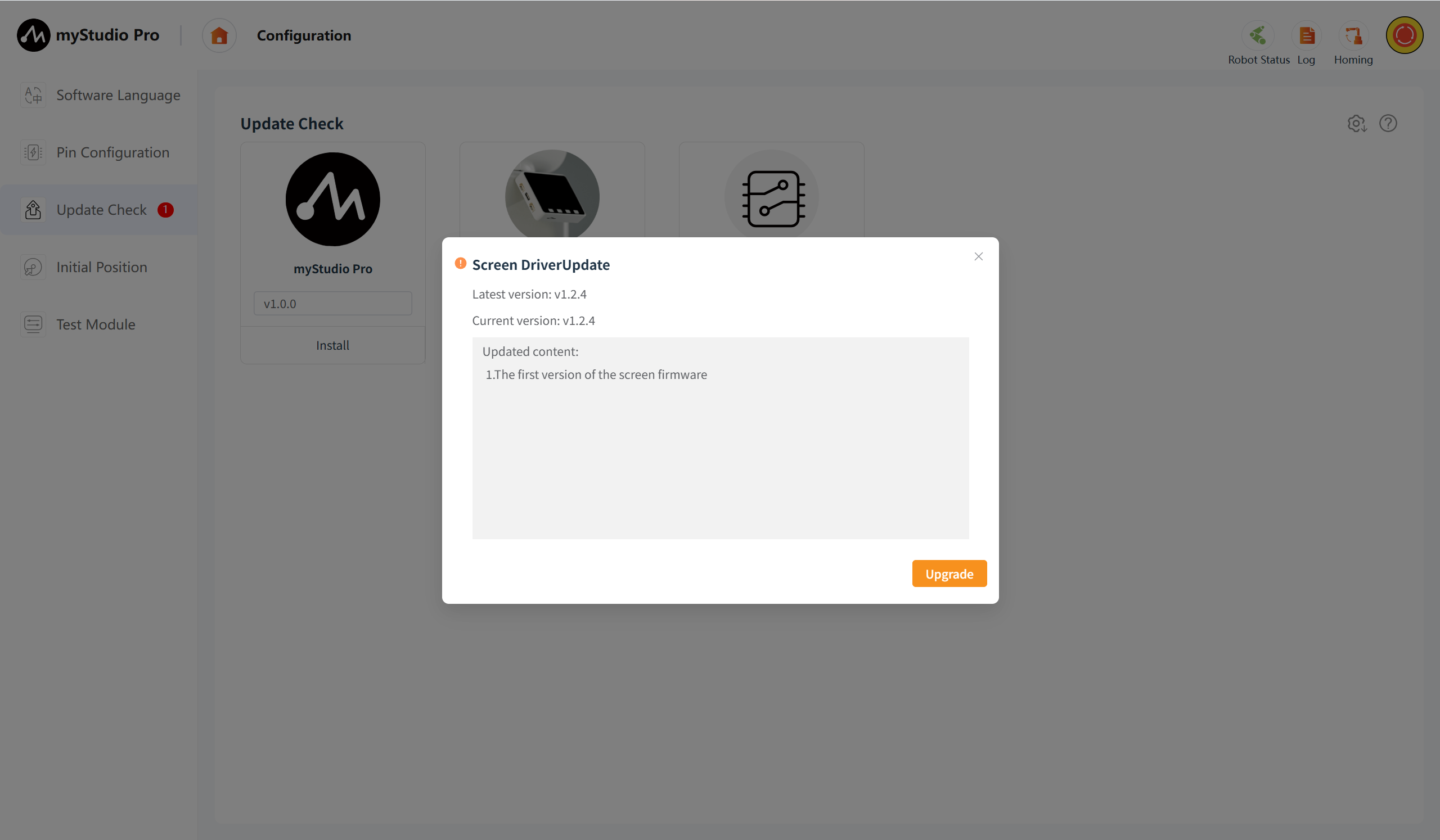
The downloaded firmware can undergo the "update" operation. After clicking the "update" button, a version information pop-up window will be displayed, including the latest version, the current version, and the updated content of the version.
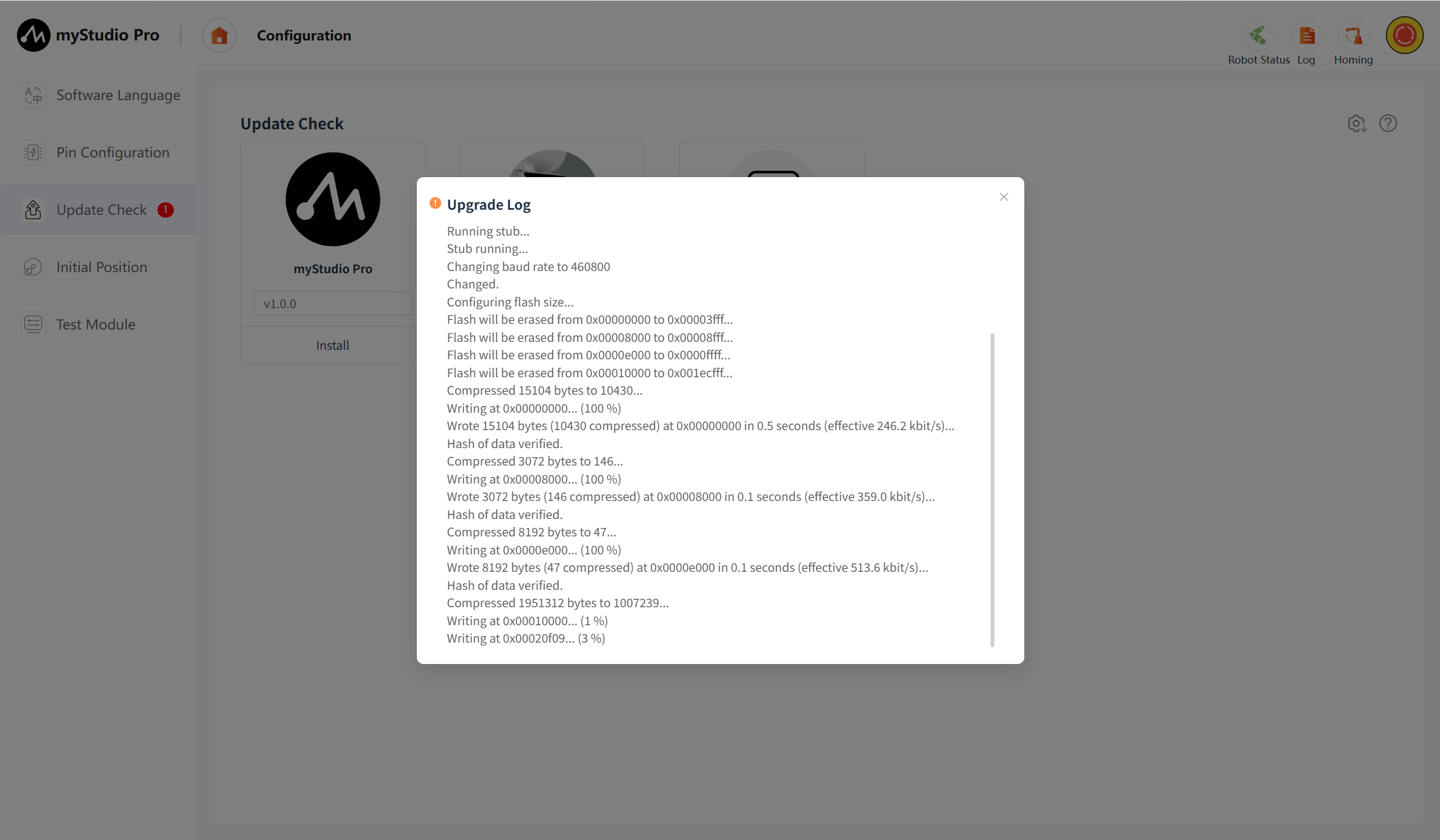
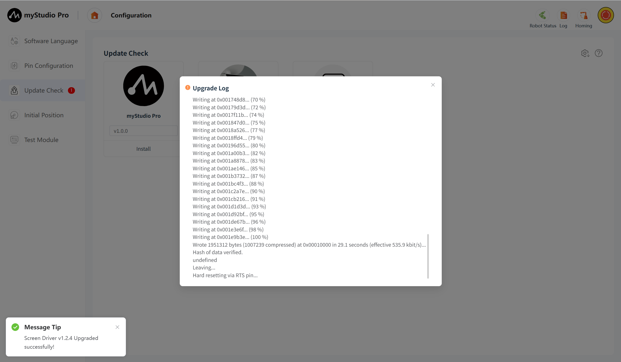
Click the "Upgrade" button, and the screen firmware upgrade operation will be initiated. During the upgrade process, the upgrade log will be displayed.
Motion firmware upgrade
Version Number
If a new version is detected, it will be displayed; otherwise, the last selected version will be the default display.
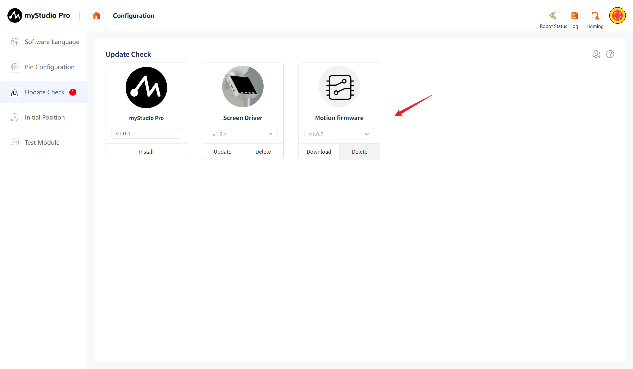
The icon on the right side of the current version is green, the version that has not been downloaded is gray, and the version that has been downloaded but not updated is orange.
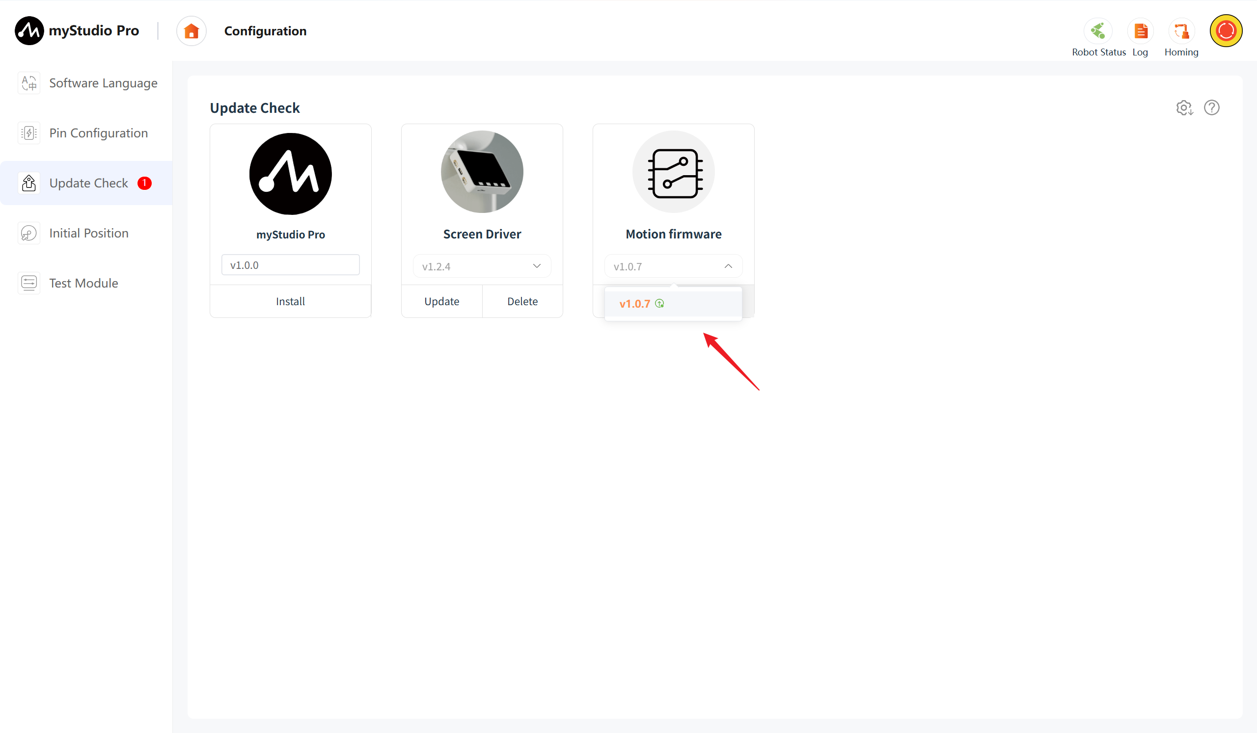
When the version has not been downloaded, the "Delete" button is disabled while the "Download" button is available. Clicking the "Download" button will initiate the download of the version firmware, and a download progress bar will be displayed. After the download is complete, the delete button becomes available and the【Update】button is displayed.
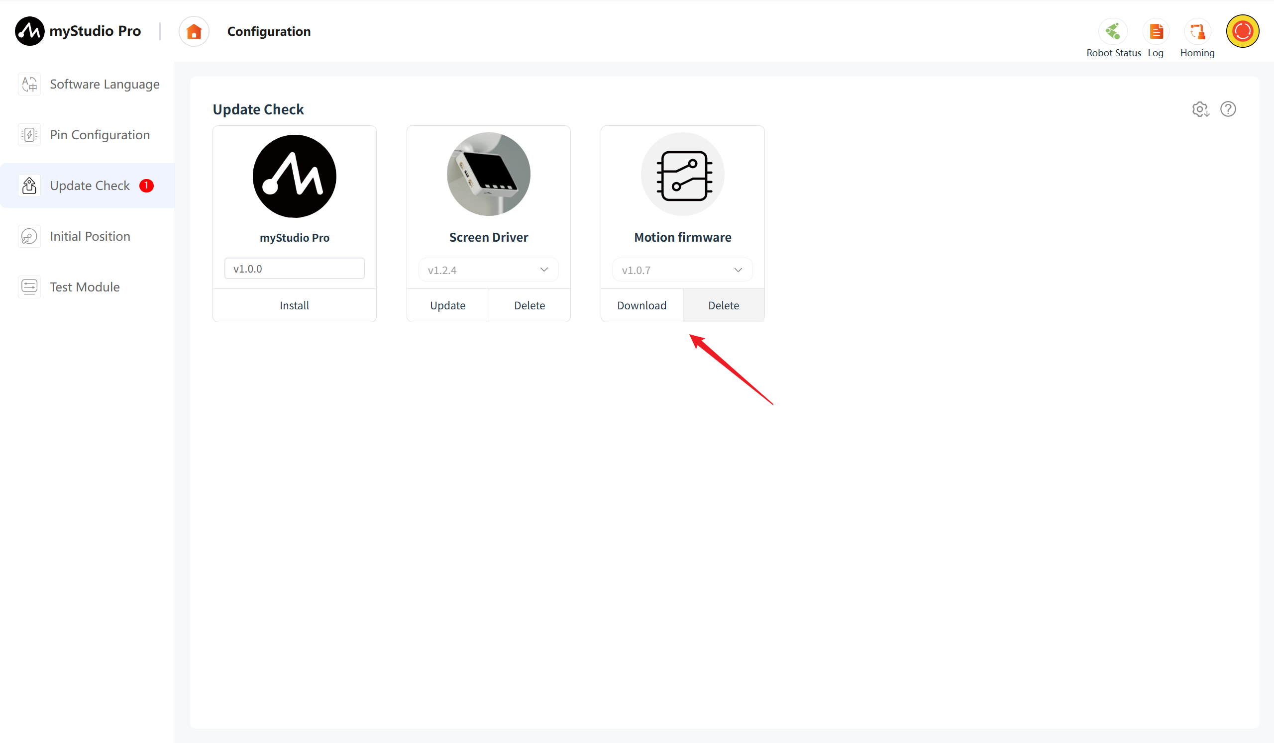
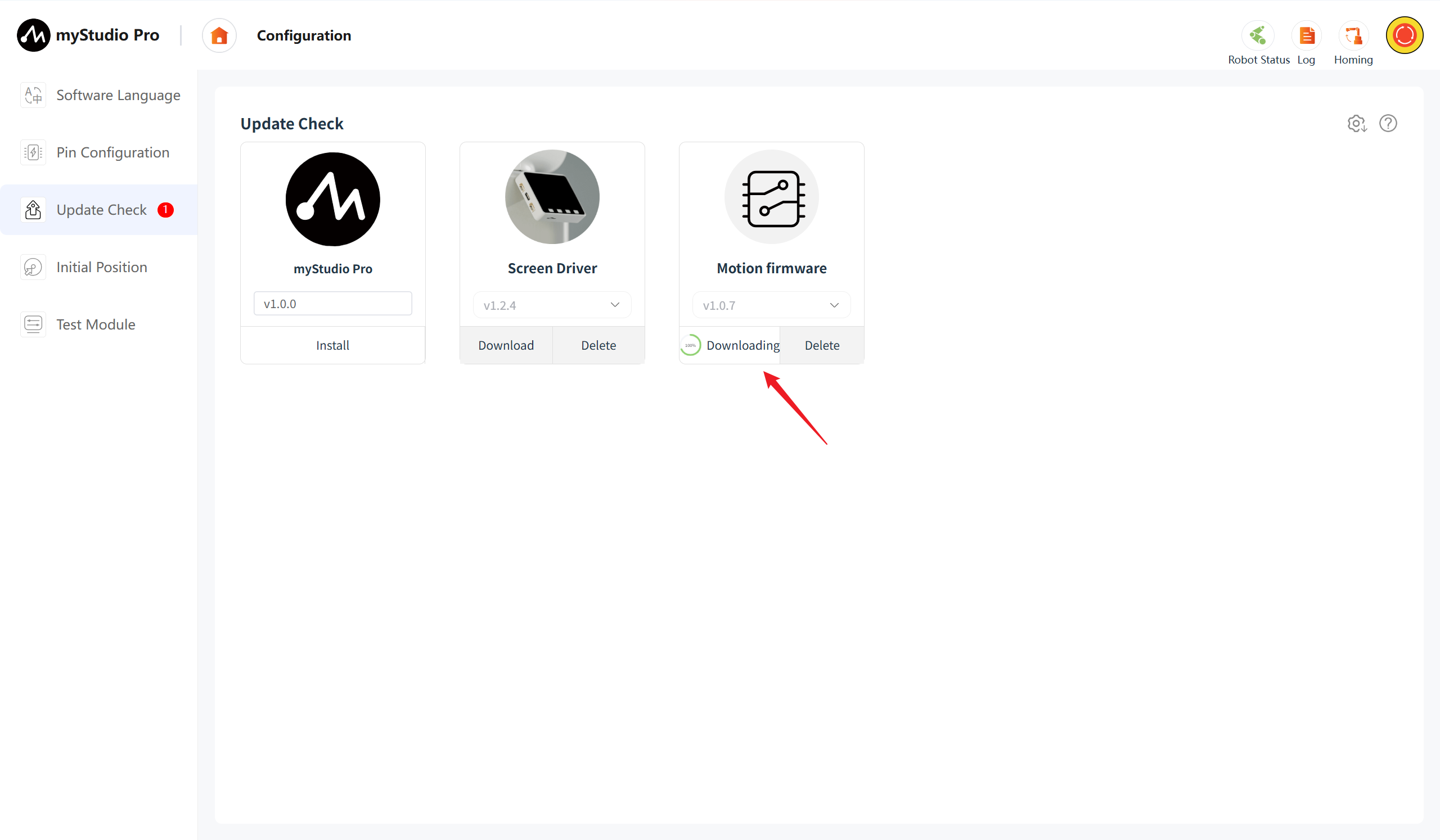
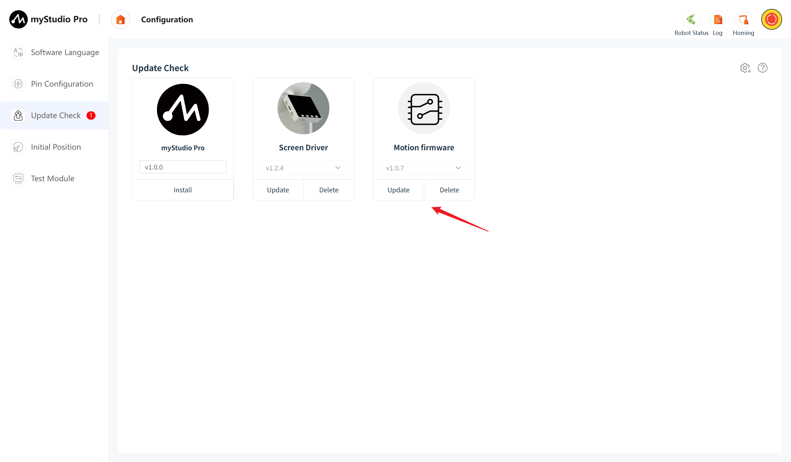
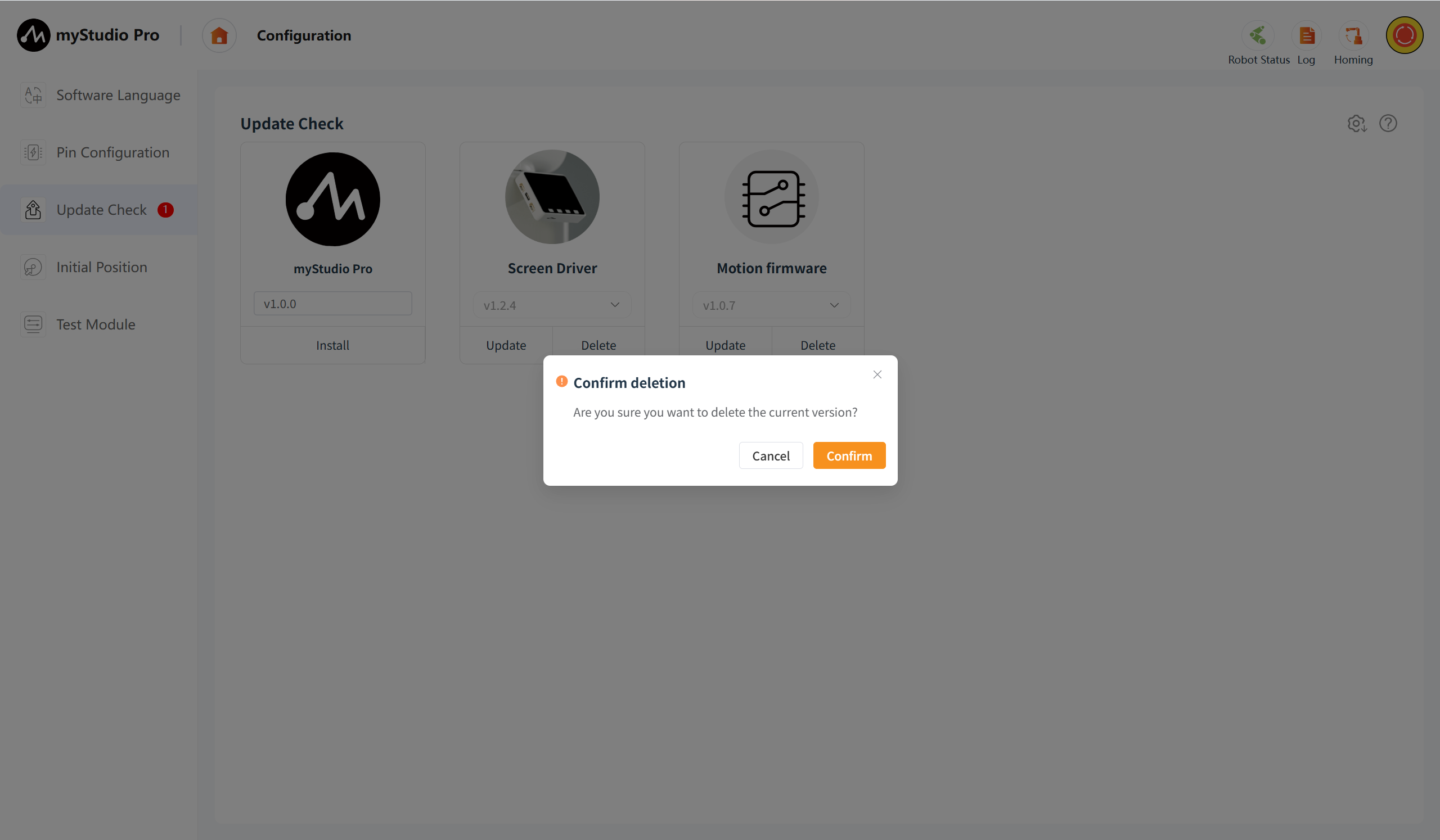
The downloaded firmware can be deleted. Clicking the "delete" button will bring up a confirmation window for the deletion.
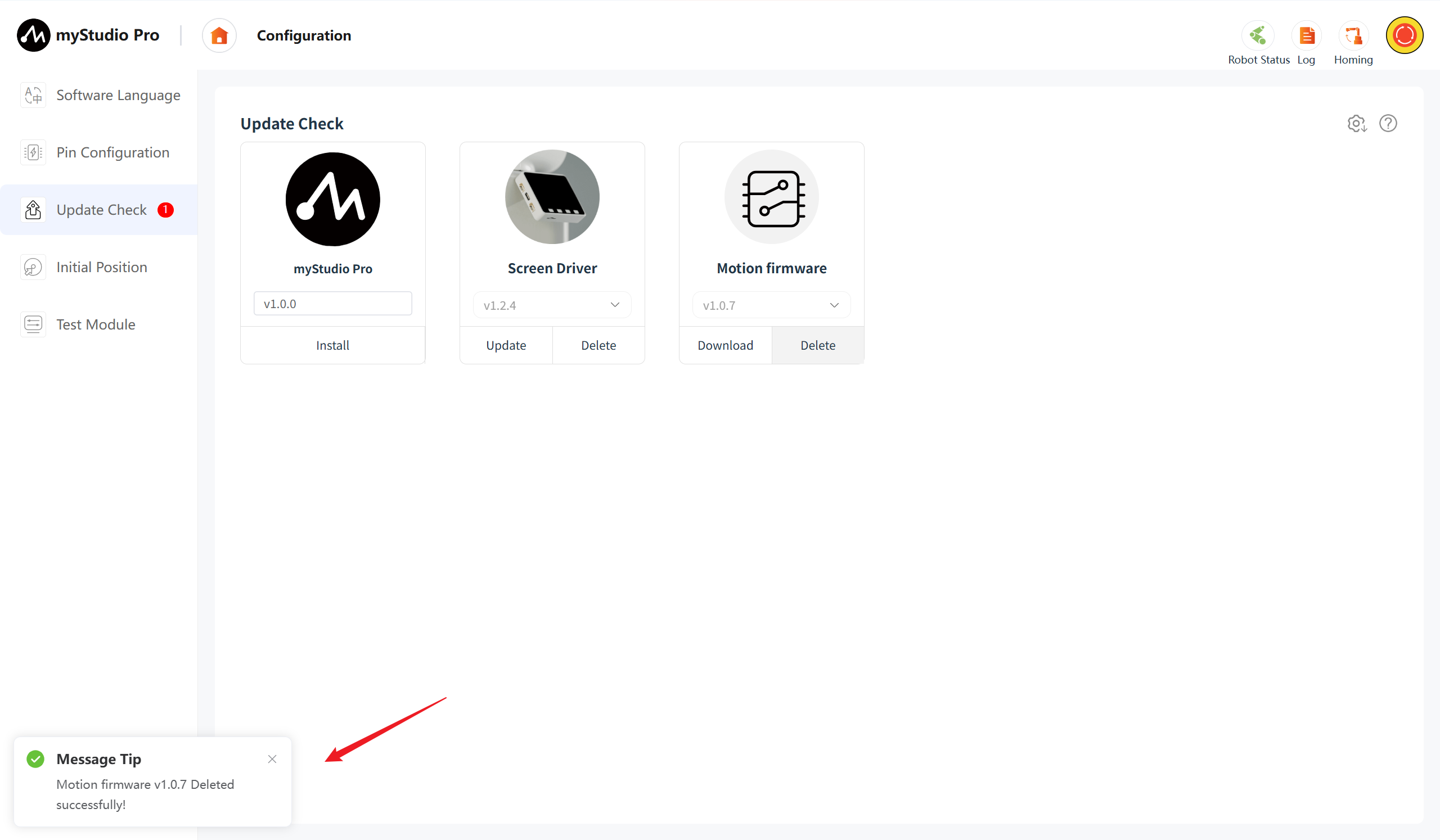
The downloaded firmware can undergo the "update" operation. After clicking the "update" button, a version information pop-up window will be displayed, including the latest version, the current version, and the updated content of the version.
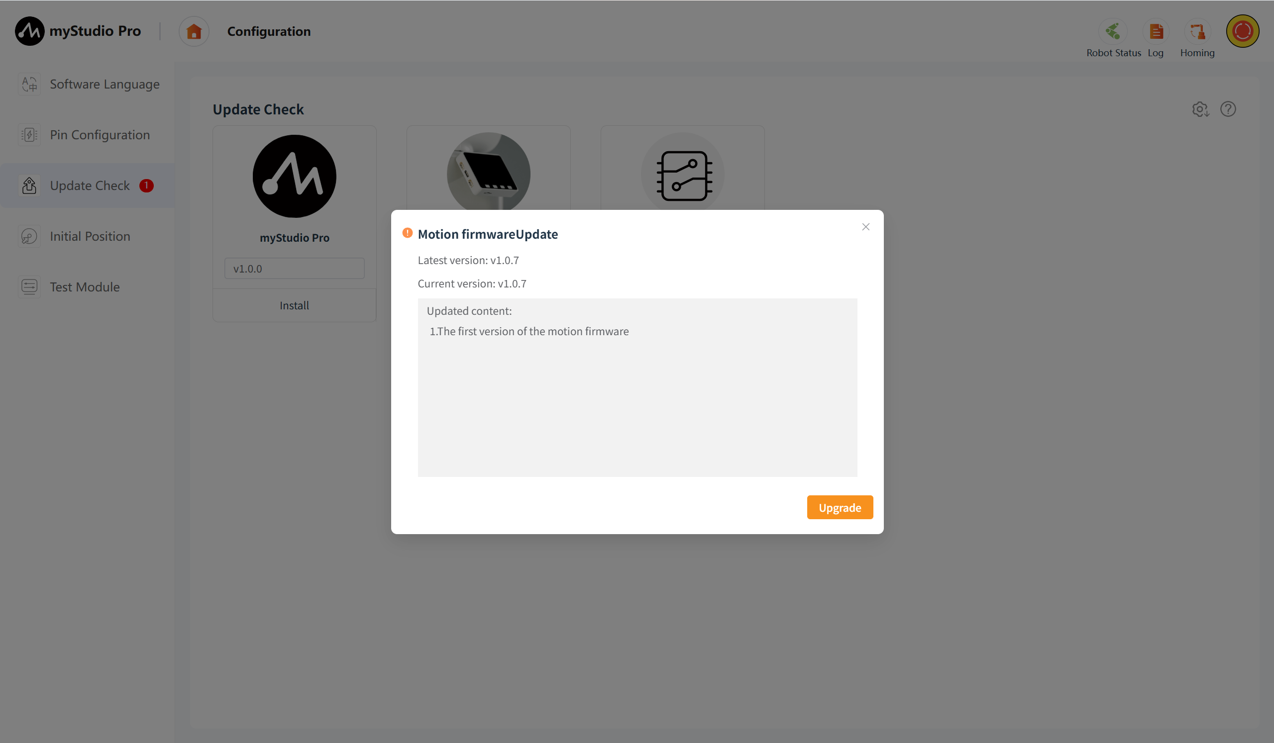
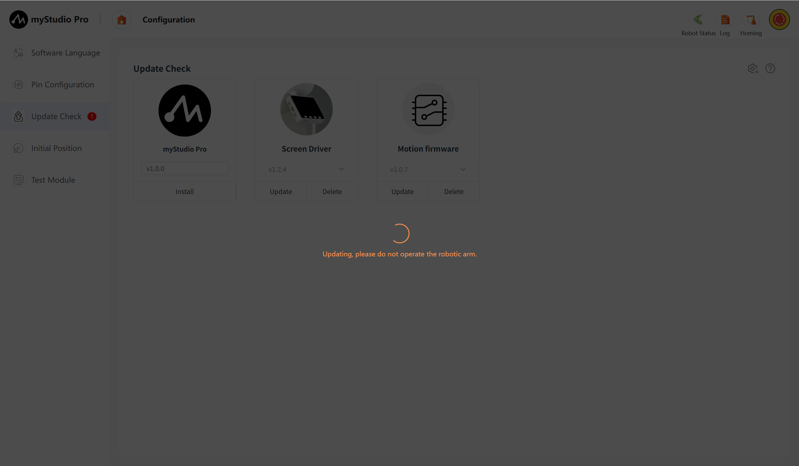
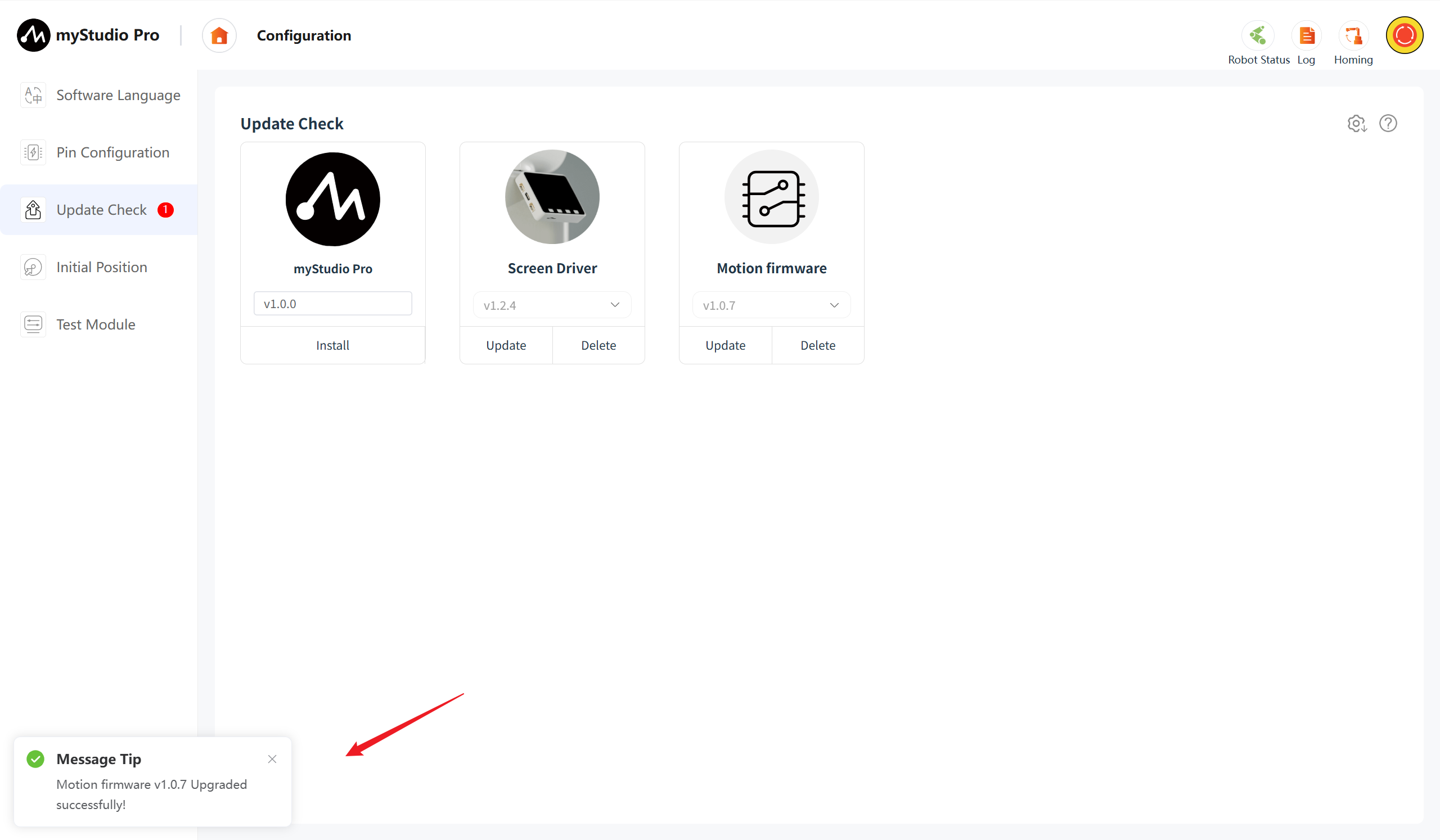
Click the "Upgrade" button, and the firmware upgrade operation for the device will be initiated. During the upgrade process, an "Upgrade Loading" message will be displayed until the upgrade is completed and the loading message disappears.
5 Initial Position
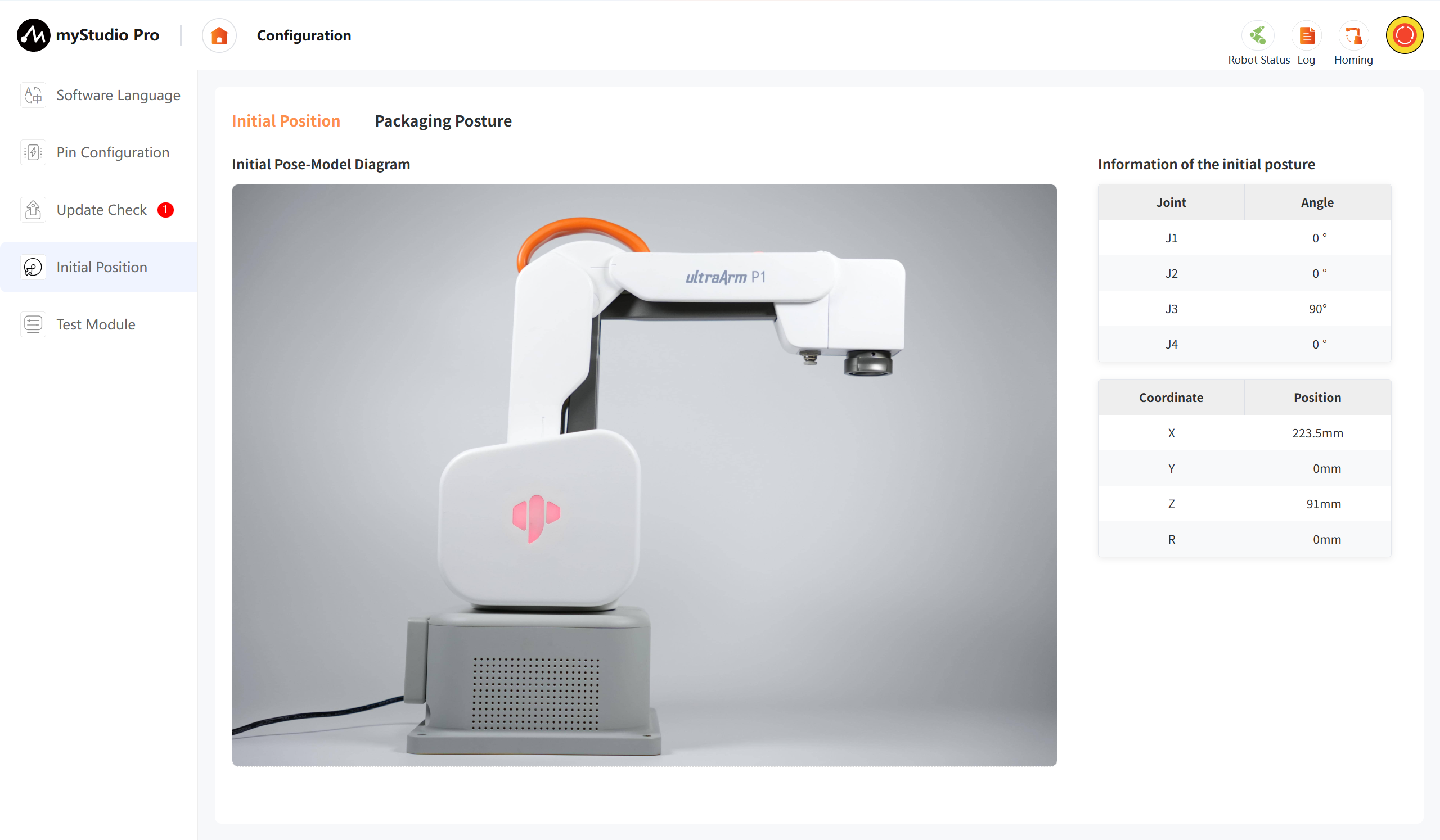
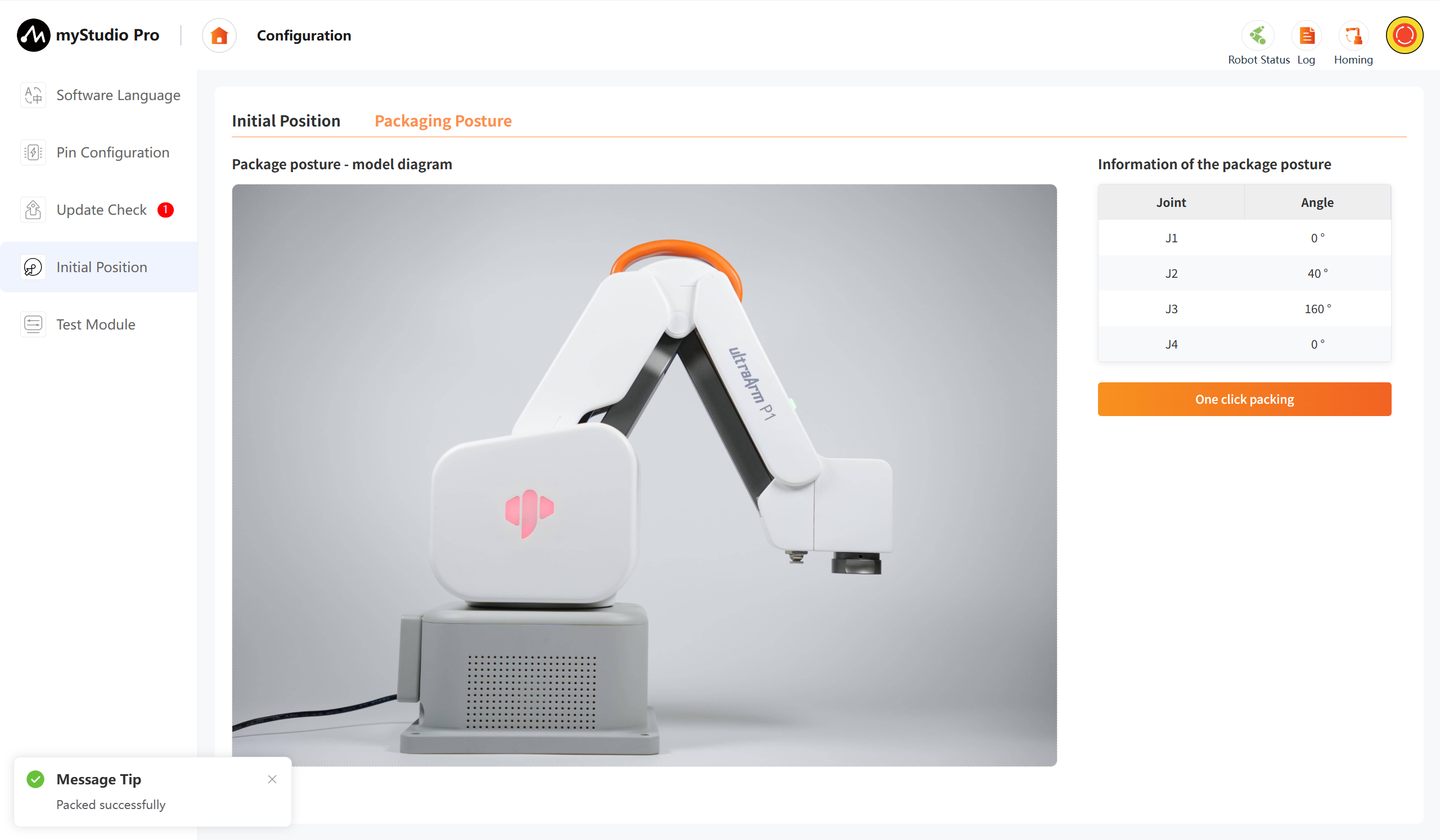
Click the Initial Position icon button, and you will enter the initial position page. This page contains the Initial Position and Packaging posture contents. You can switch the content to be accessed by using the toggle buttons.
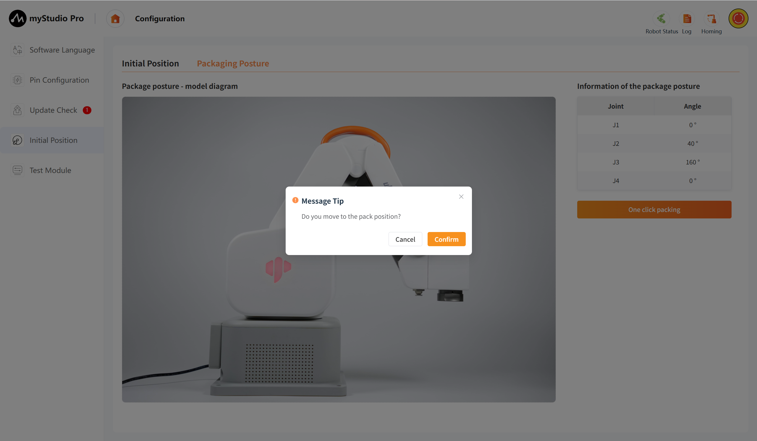
Packing posture page: Displays the model diagram of the packing posture of the robotic arm, joint angle information, and the one click packing button. This button is a functional button. When this button is clicked, the robotic arm will move to the packing posture.
6 Test Module
Clicking the Test Module icon button will take you to the test page.
Test page: Mainly tests the communication connection of the robotic arm, firmware version, servo status, etc.
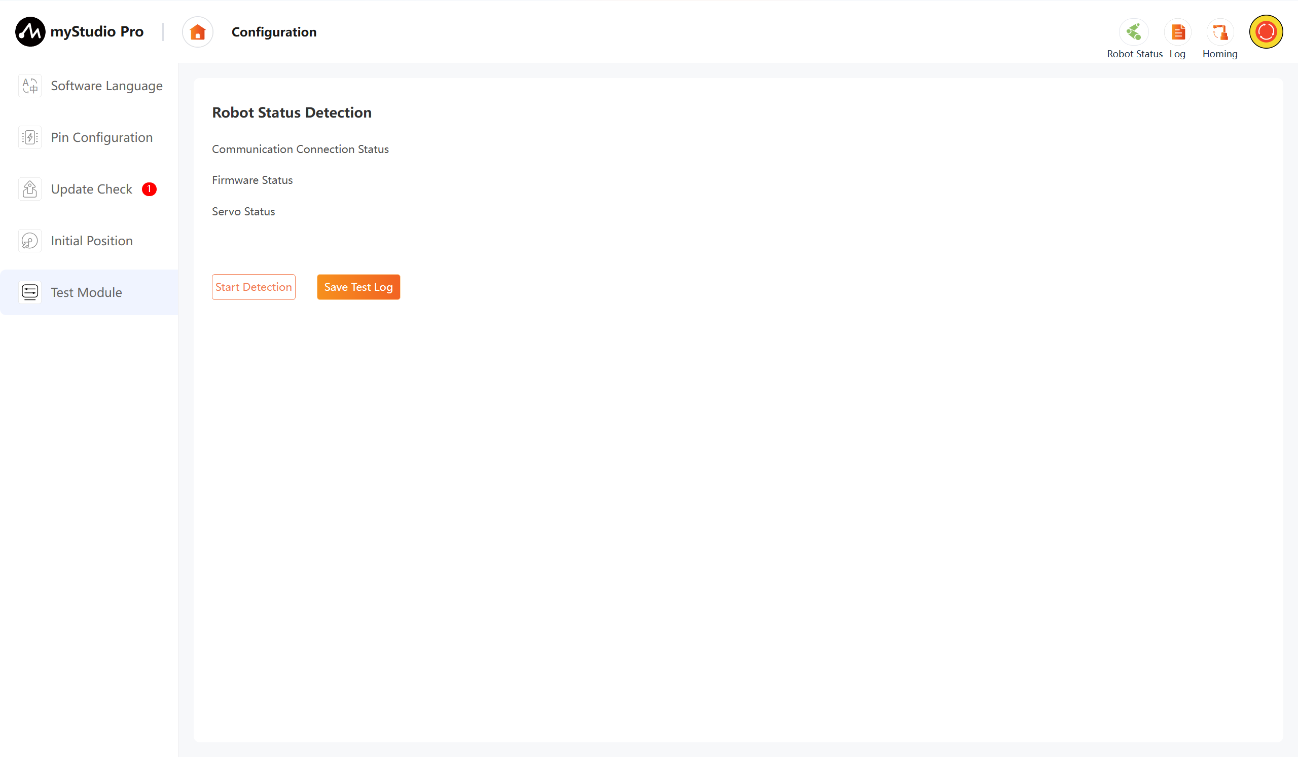
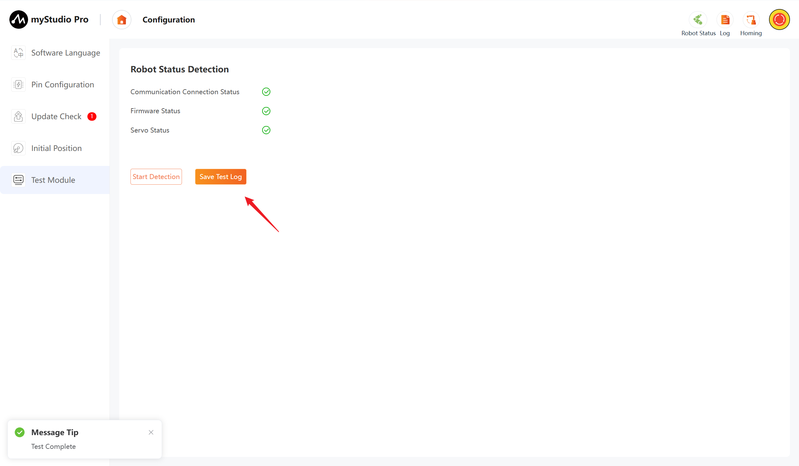
Click the "Start Detection" button, and the test can begin.
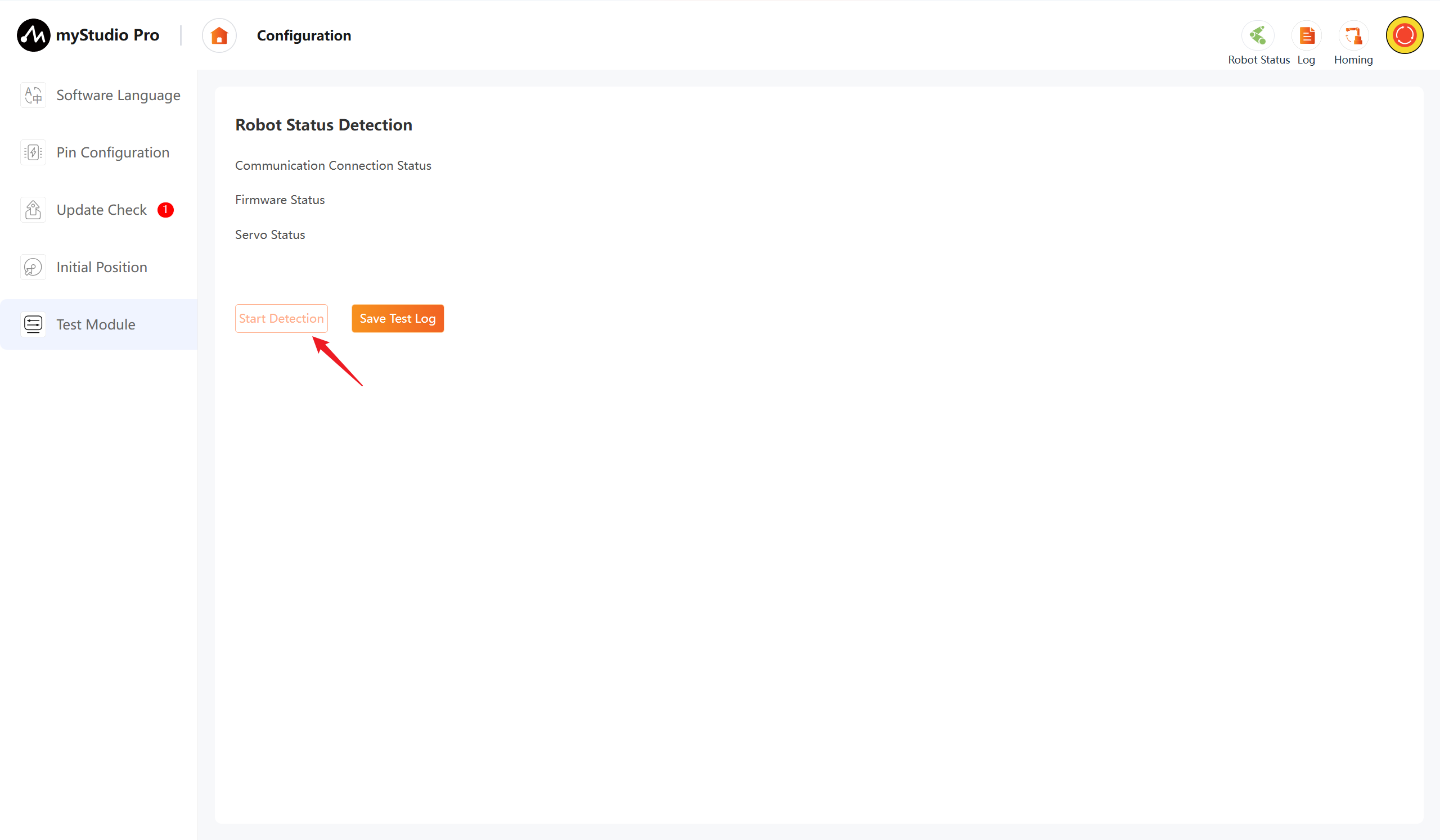
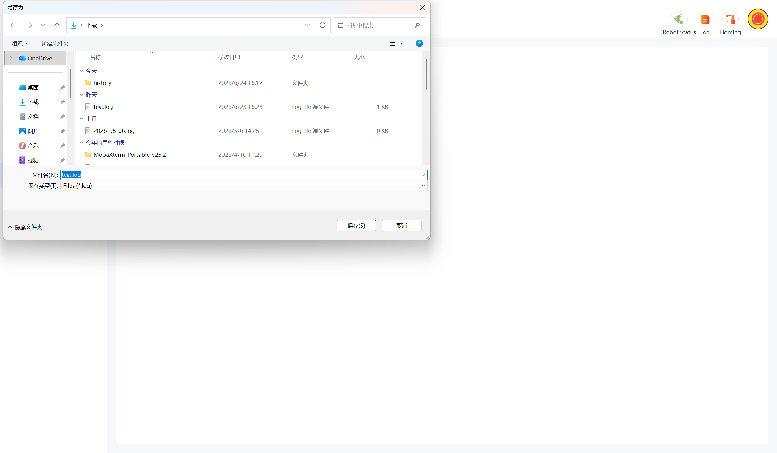
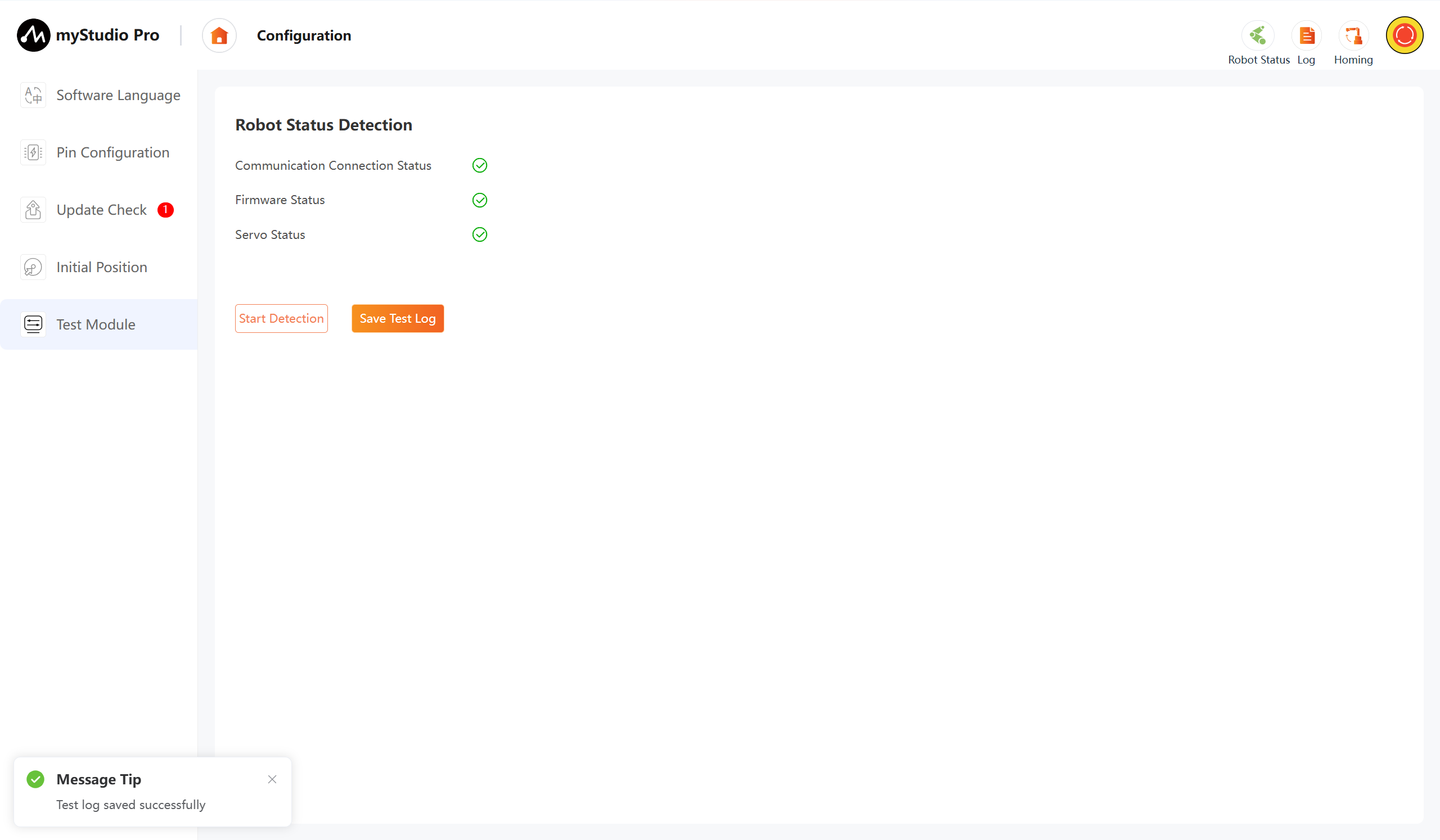
After the test is completed, click the "Save Test Log" button. After each test item is completed, it will display whether the result of this test is passed or not. Green indicates normal, while any other color indicates abnormal. The test results can be saved to a local log file for viewing the specific test content.