Scene Apps
Main Page
After entering the main interface of the scene application, you can immediately find the two core functions of "Write and Draw" and "Laser carving". Clicking on them will directly jump to the corresponding editing page.
Write and Draw
Main Page
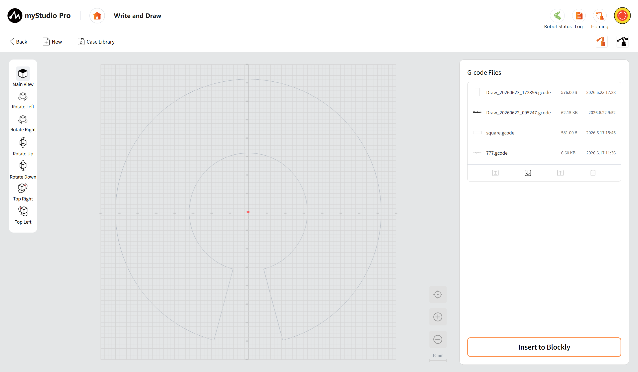
The main interface serves as the core entry point for managing G-code files, previewing trajectories, and executing jobs. It is mainly divided into the following areas:
Top Toolbar
It provides five function buttons: Back, New, Case Library, Quick Move, and Free Move. The New button is used to enter the workbench to create patterns; the Case Library contains pre-set G-code files; the Quick Move supports point-by-point debugging and special point settings; and the Free Move allows for manual dragging of the robotic arm to the target position.
Back: Click the button to return to the main page of the scene application.
New: After clicking the button, you can enter the writing and drawing work to create and edit a new project.
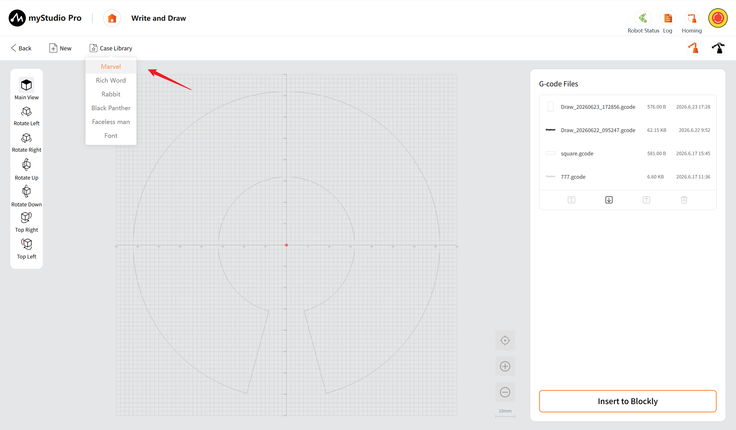
Case Library: The drop-down menu enables you to browse and select the pre-set programmable G-code files available within, and quickly load their processing trajectories into the intermediate preview area.
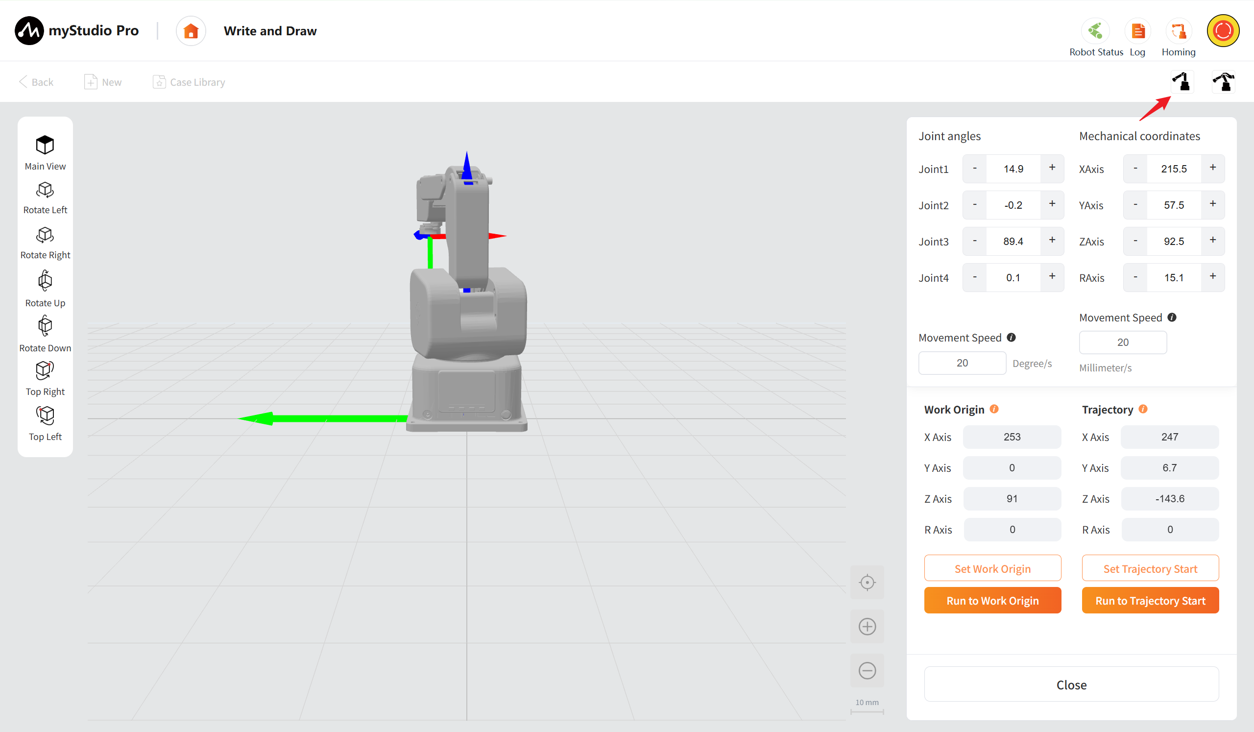
Quick Movement: Clicking will open the quick movement page, which supports setting the work origin, trajectory starting point, precise point position adjustment, and real-time coordinate reading.
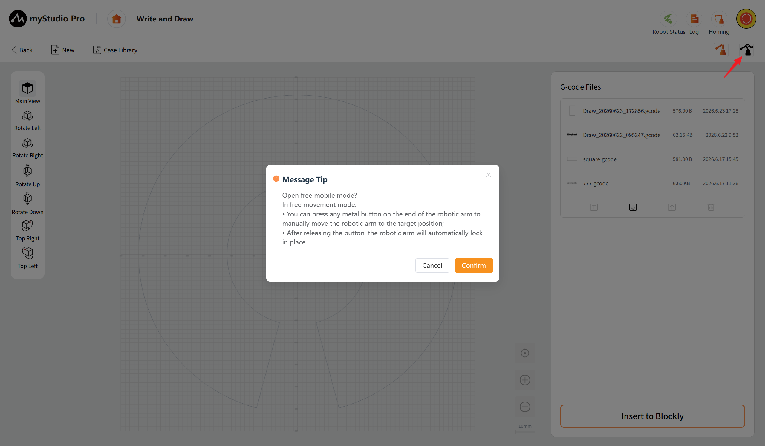
Free Movement: When clicked, a message box will pop up. After confirming, the robotic arm can be manually dragged and moved to the initial position, simplifying the debugging process.
Left View Control Area
This area provides the main view (restoring the default perspective), left rotation/right rotation/upward rotation/downward rotation (adjusting the viewing angle), and left upper point/right upper point (quickly positioning the view center to the upper left or upper right point of the work area), facilitating users to check the processing trajectory from multiple dimensions.
Main View: After clicking the button, the 3D preview area will be restored to its default initial perspective. The main view of this page is set as a top-down view by default.
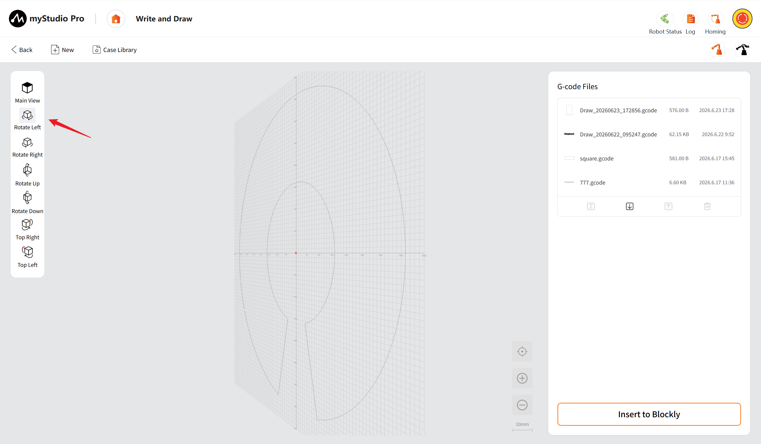
Rotate Left: Support single-click and long-press. Click to rotate 15 degrees, and long-press to rotate continuously to the left at a speed of 30 degrees per second until you release the button to stop.
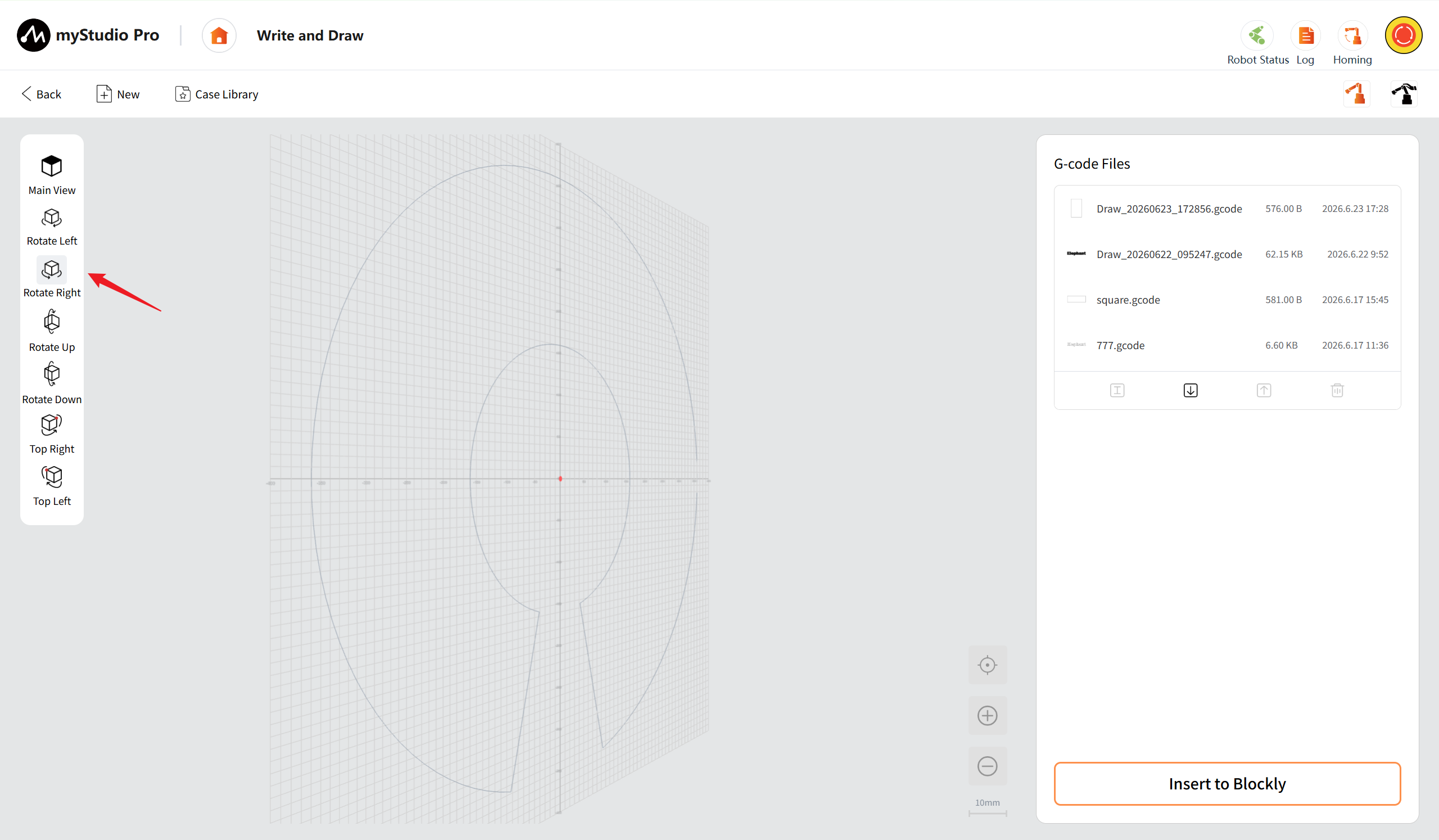
Rotate Right: Support single-click and long-press. Click to rotate 15 degrees, and long-press to rotate continuously to the right at a speed of 30 degrees per second until you release the button to stop.
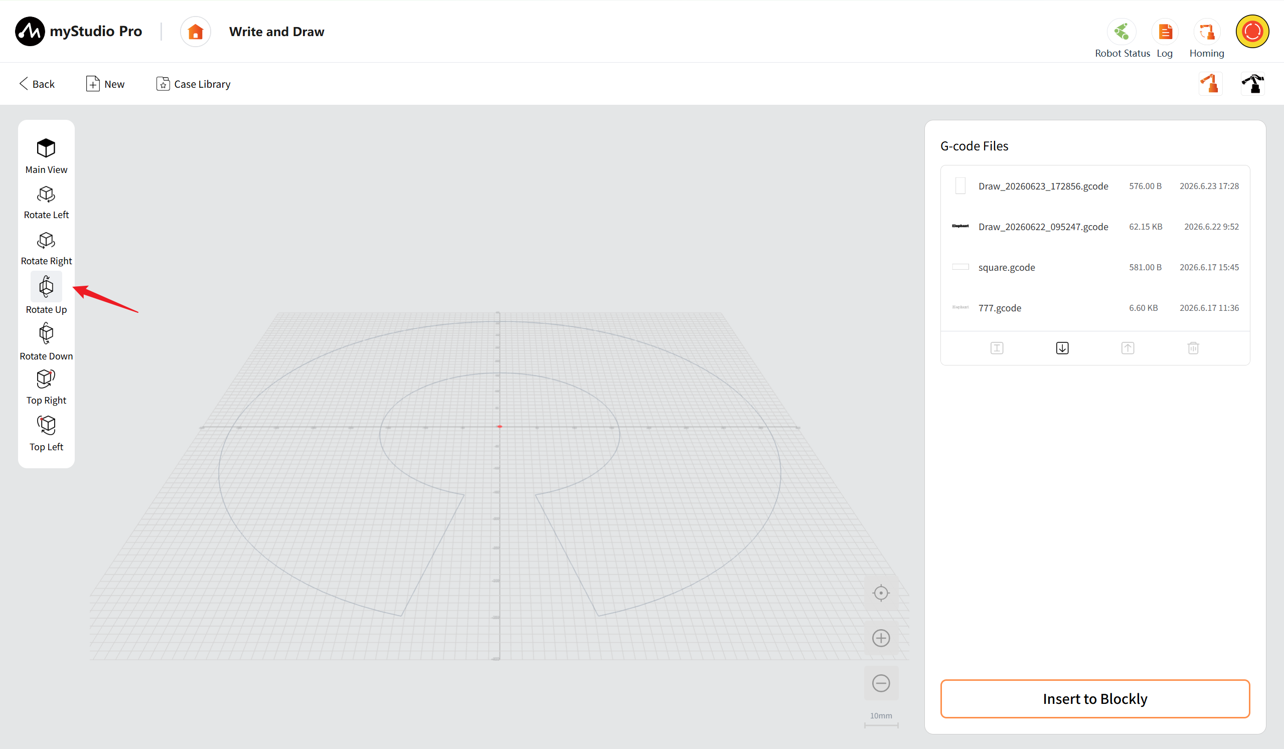
Rotate Up: Support single-click and long-press. Click to rotate 15 degrees, and long-press to rotate upwards at a speed of 30 degrees per second continuously until the button is released to stop.
Rotate Down: Support single-click and long-press. Click to rotate 15 degrees, and long-press to rotate downward at a speed of 30 degrees per second continuously until you release the button to stop.
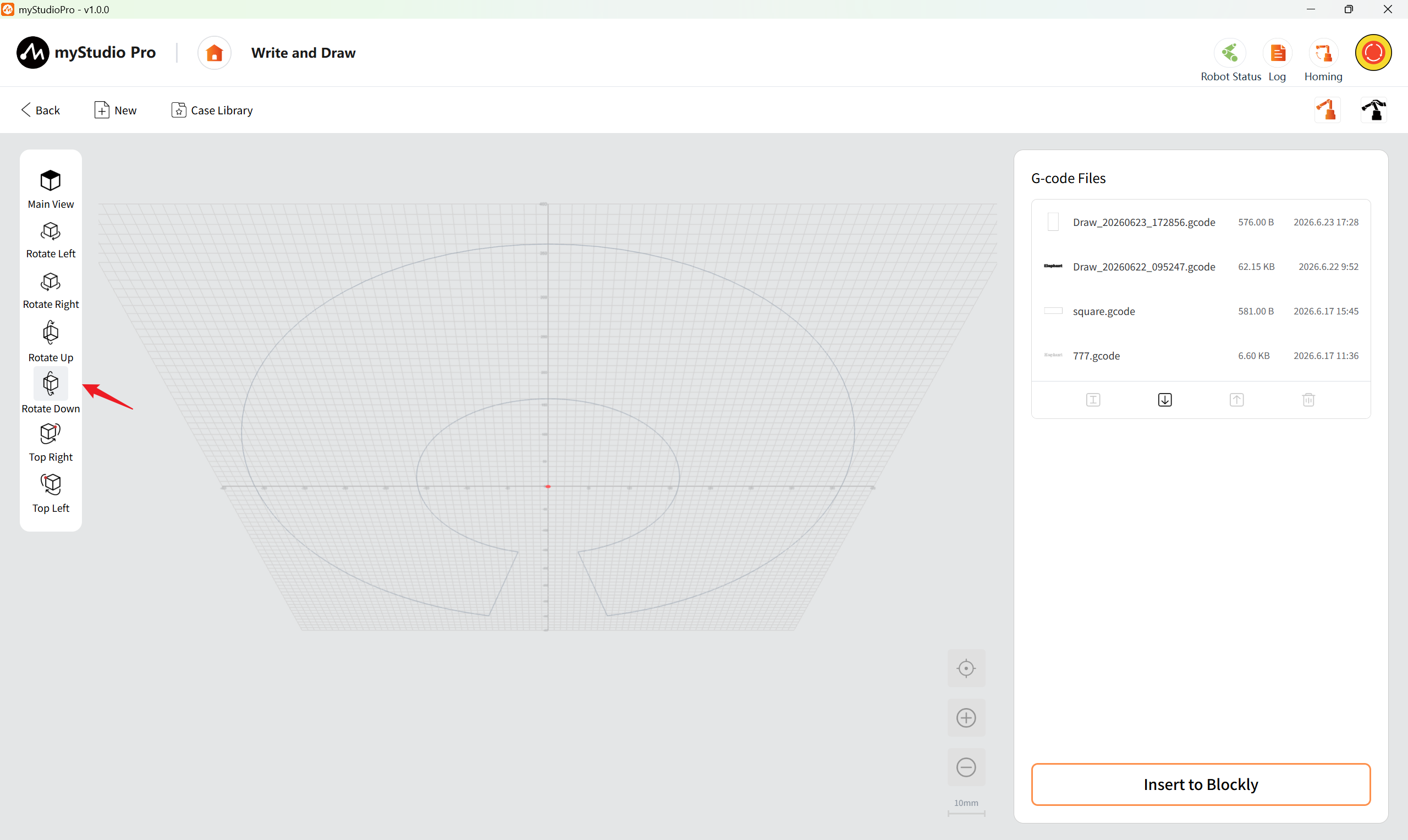
Top Right: After clicking the button, the viewing center will be quickly positioned to the top right point of the work area.
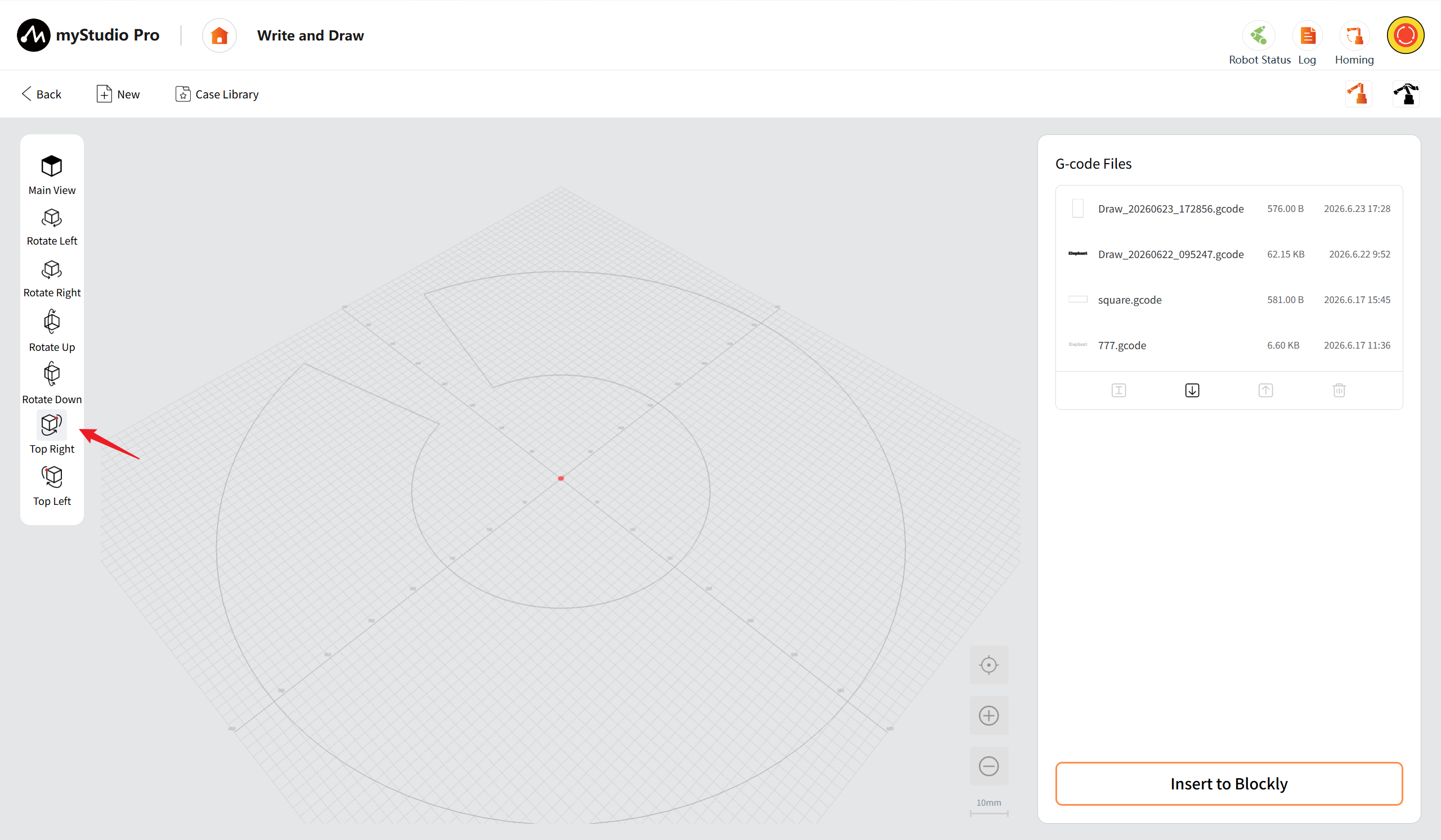
Top Left: After clicking the button, the viewing center will be quickly positioned to the upper left point of the work area.
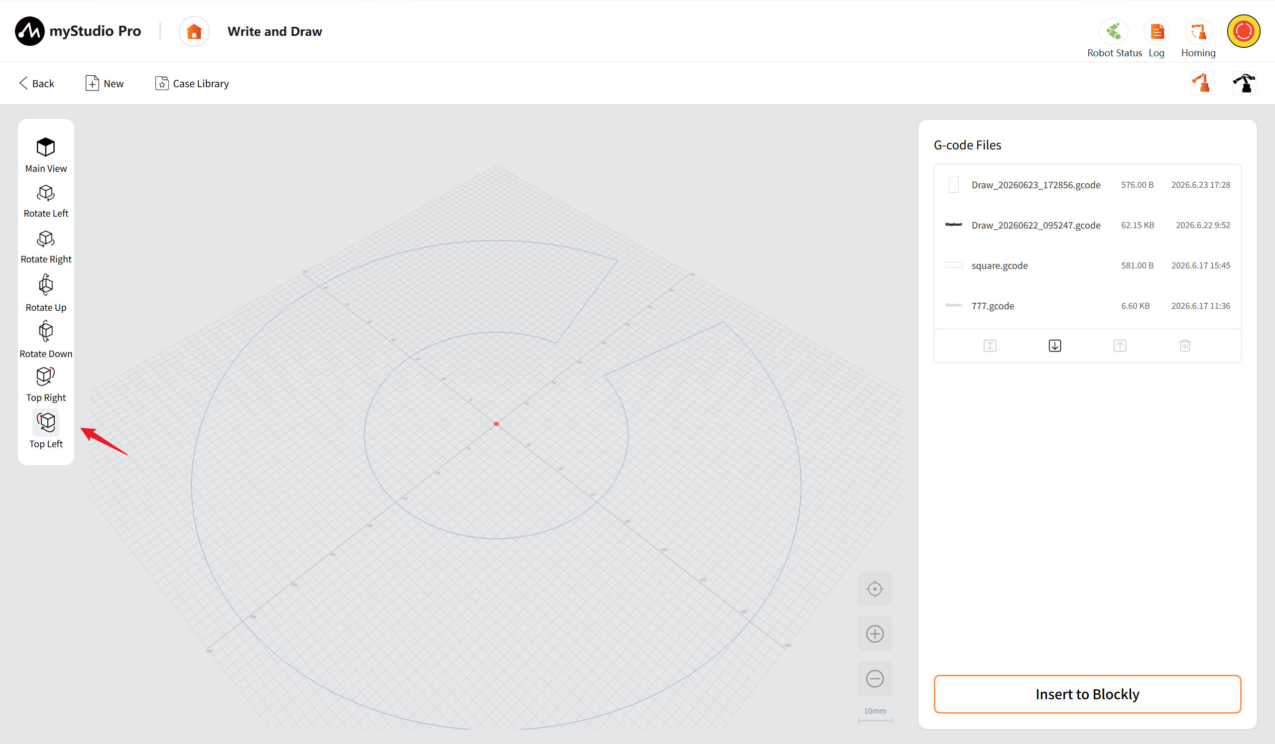
3D Trajectory Preview Area
Displays the machining trajectory of the currently selected G-code file in a 3D format. The circular boundary represents the processing range of the robotic arm. The lower right corner provides zoom control, allowing for fine adjustment of the view.
The mouse can be used to drag for perspective movement, and the scroll wheel can determine the center point for zooming in and out.
Calibration: Click the "Calibration" button to restore the view to the default main perspective and the zoom ratio to the default value (10mm/grid) .
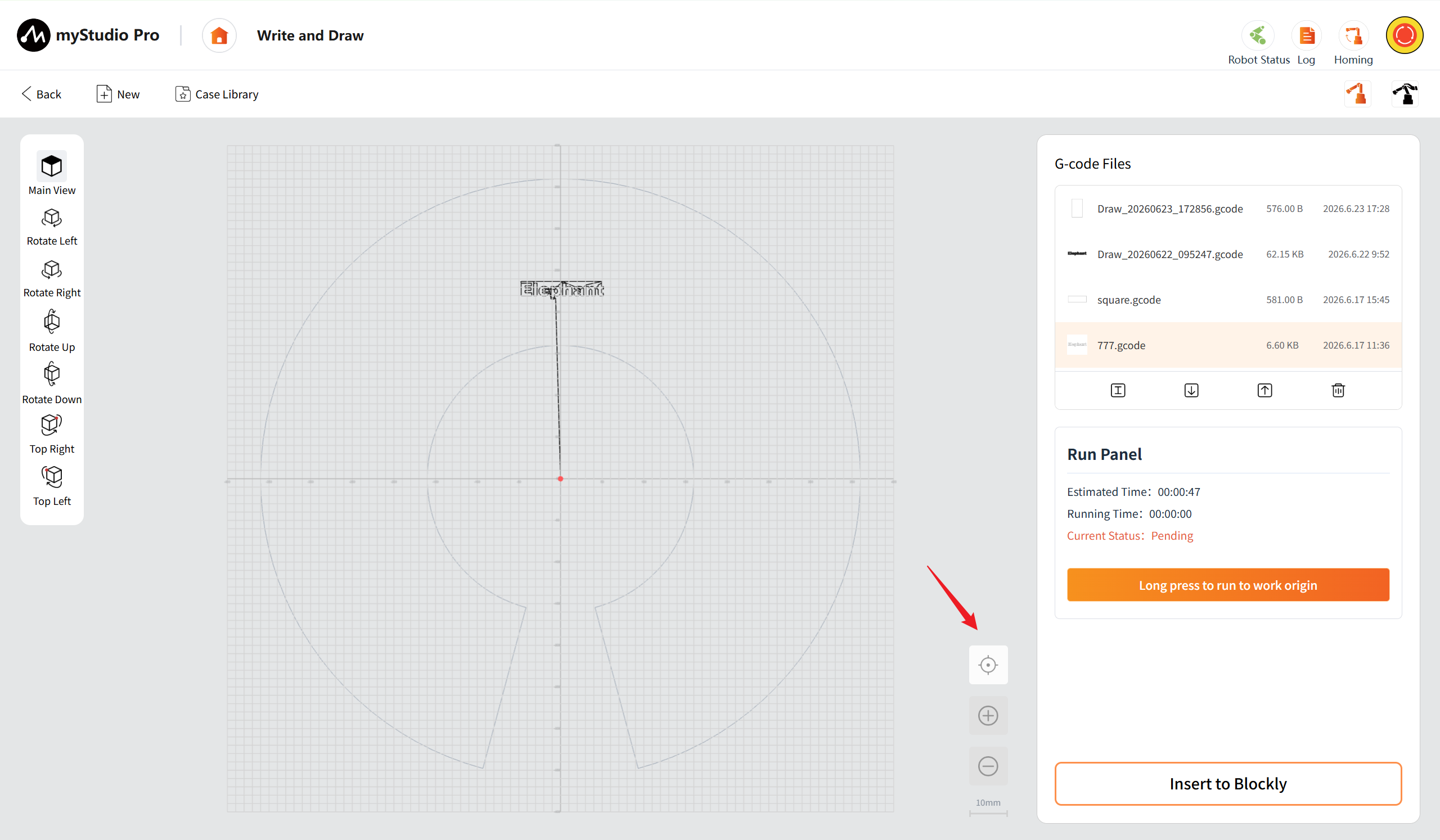
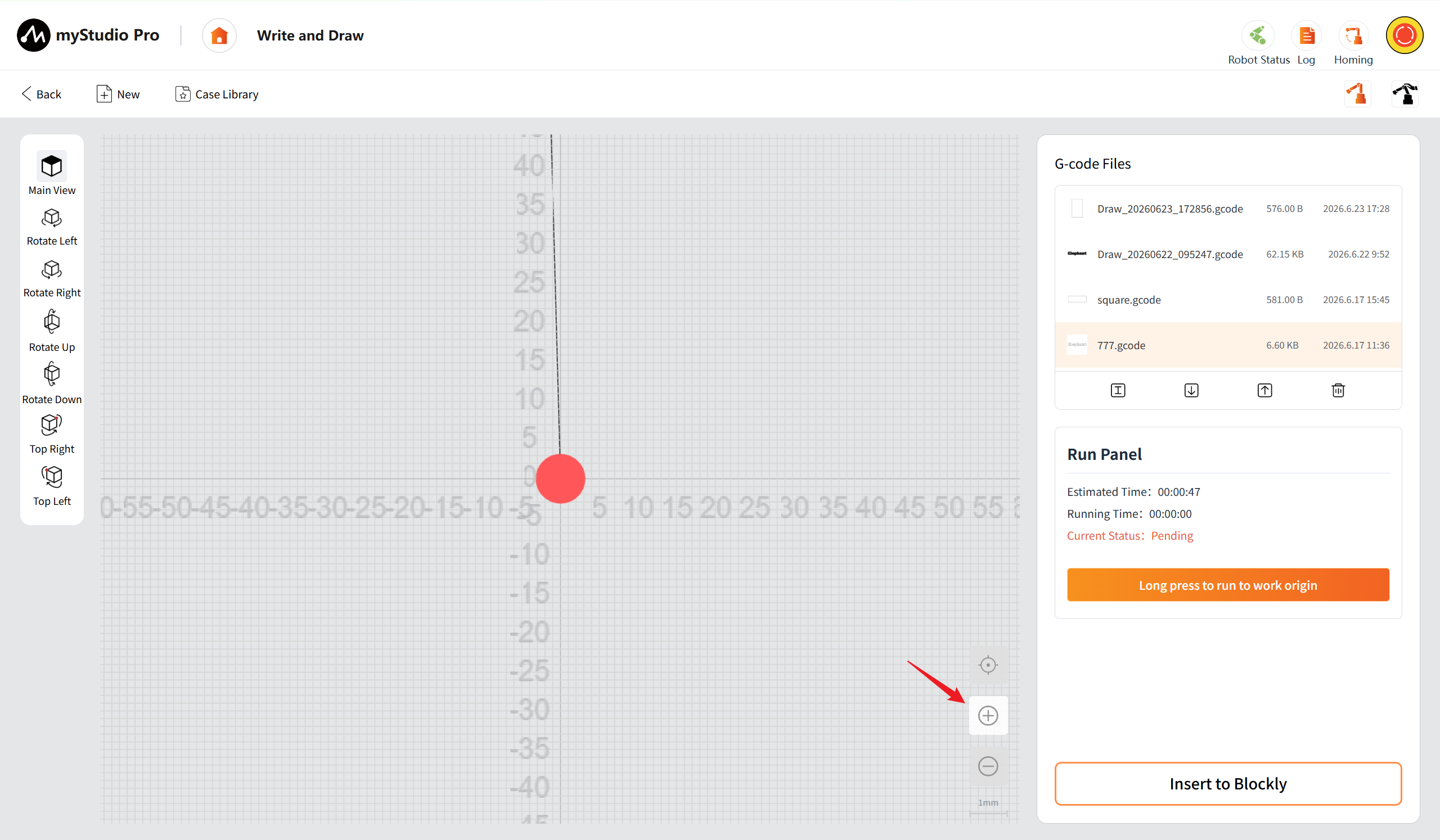
Zoom In: Click the "Zoom In" button once to increase the view level by one step. The scale will switch to a smaller value according to the preset sequence (for example, from 10mm/interval to 5mm/interval). Support for continuous clicks to gradually zoom in to the minimum scale of 1mm/interval. Once the minimum scale is reached, clicking the button will have no effect.
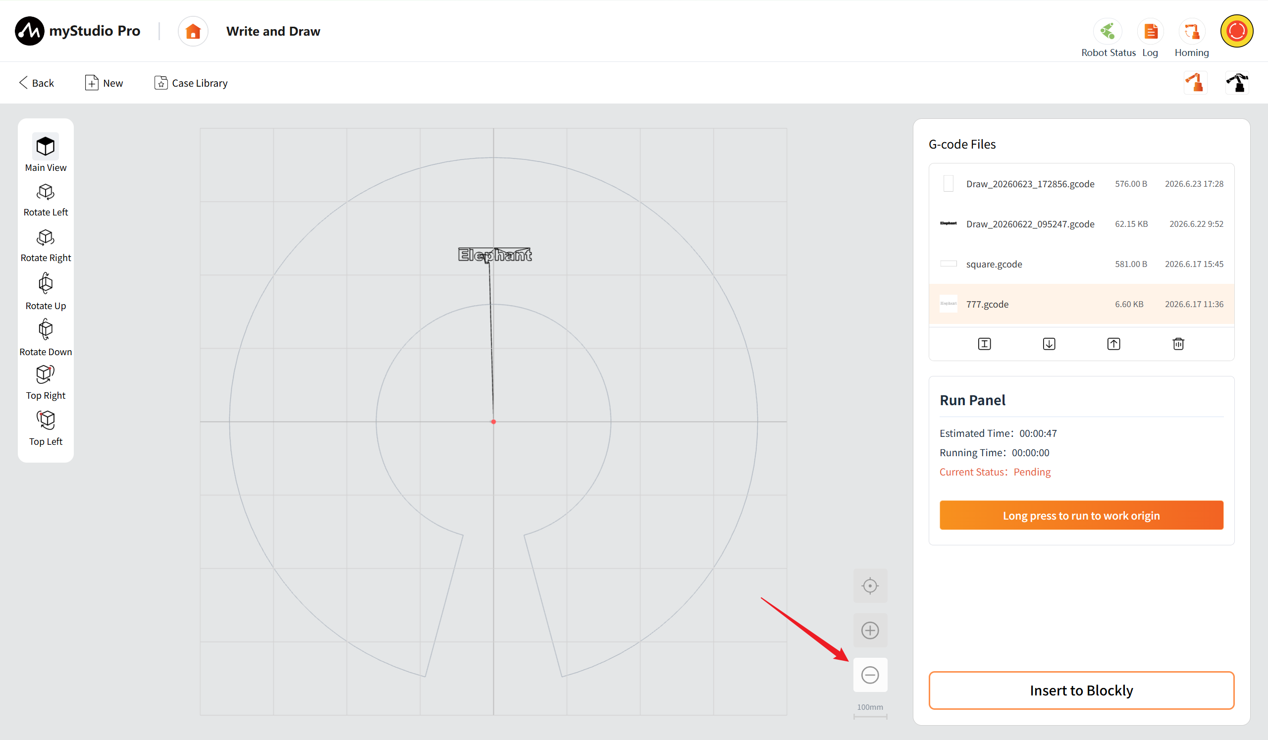
Zoom out: Click the "zoom out" button once, the view is scaled down one level, and the scale scale is switched to larger values in a preset sequence (e.g., from 10mm/ cell to 50mm/ cell). Support for continuous clicks to gradually reduce to the maximum scale of 100mm/interval. Once the maximum scale is reached, clicking the button will have no effect.
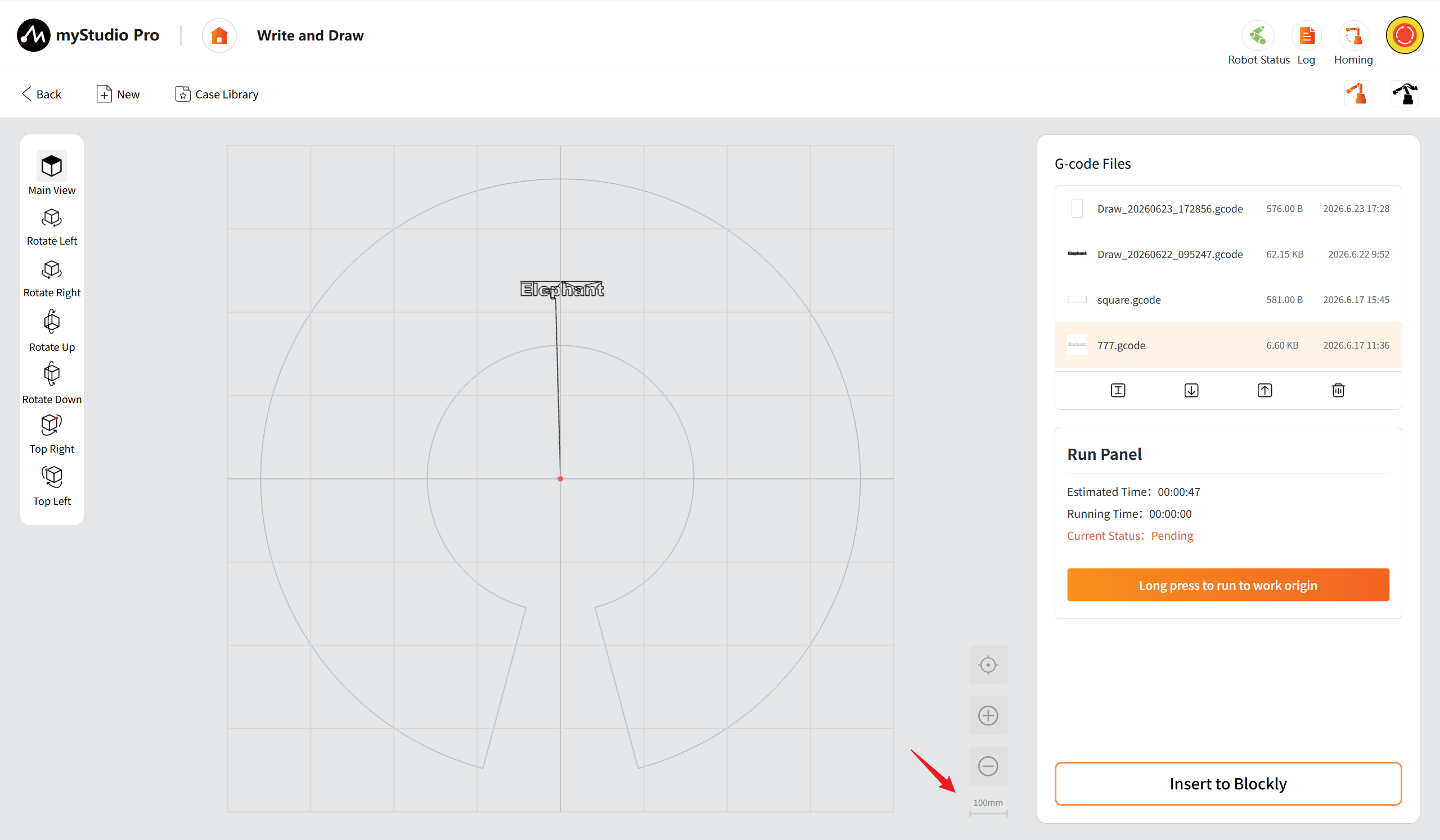
Scale: The current scale is displayed in the lower right corner, in the format "10mm", indicating the actual length represented by each small grid on the current grid.
File Management and Operation Control Area
Display the list of G-code files in reverse chronological order. It supports basic operations such as renaming, importing, exporting, and deleting. At the bottom is the run panel, which shows the estimated time consumption, running time, and running status of the current file. Inserting it into Blockly allows you to jump to the block programming interface, facilitating the construction of batch processing procedures.
G Code File List: This section displays the list of G code files. The fields of each list item include the file name, file size, and save date, and the image of each list item represents the processing pattern.

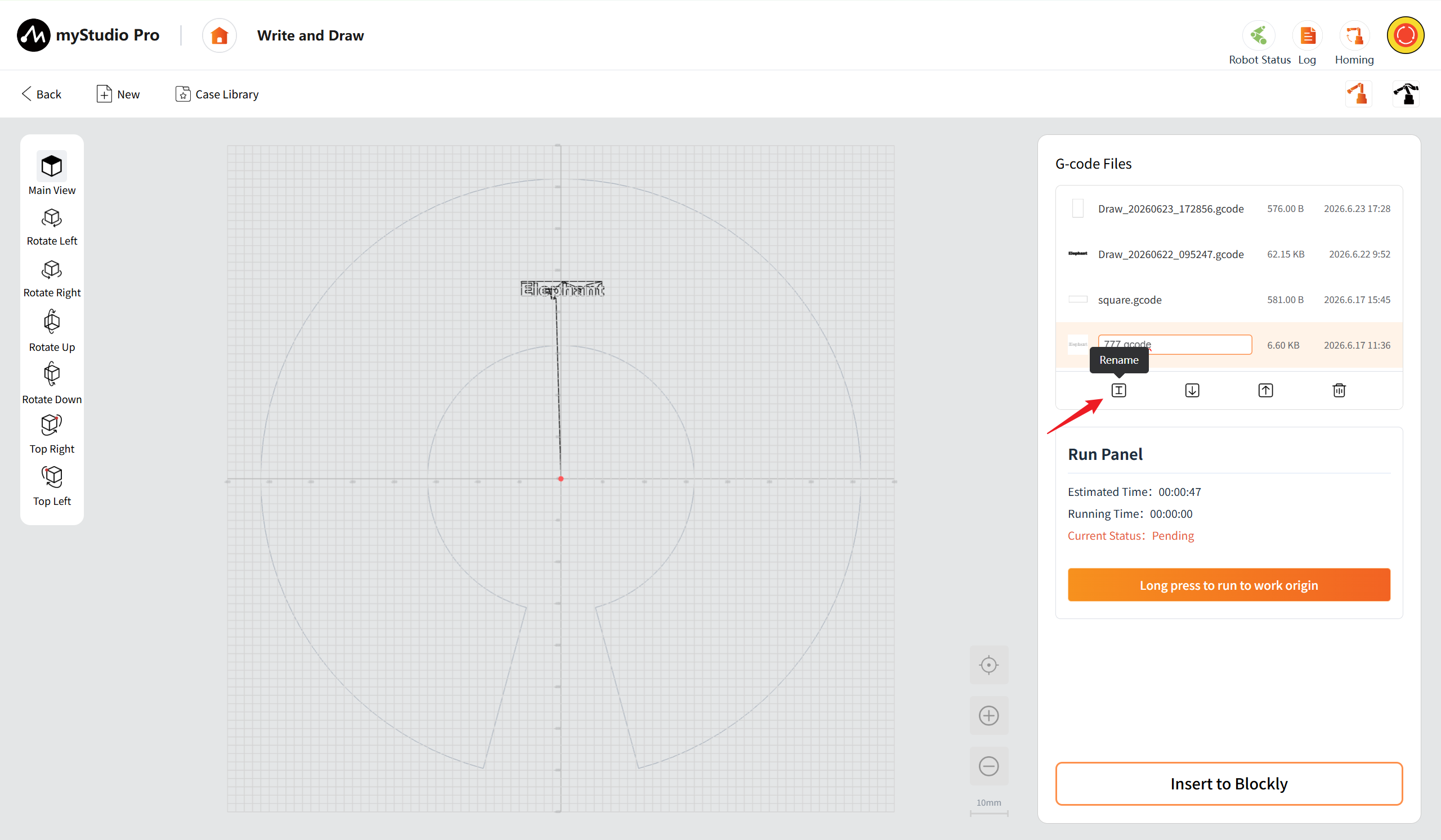
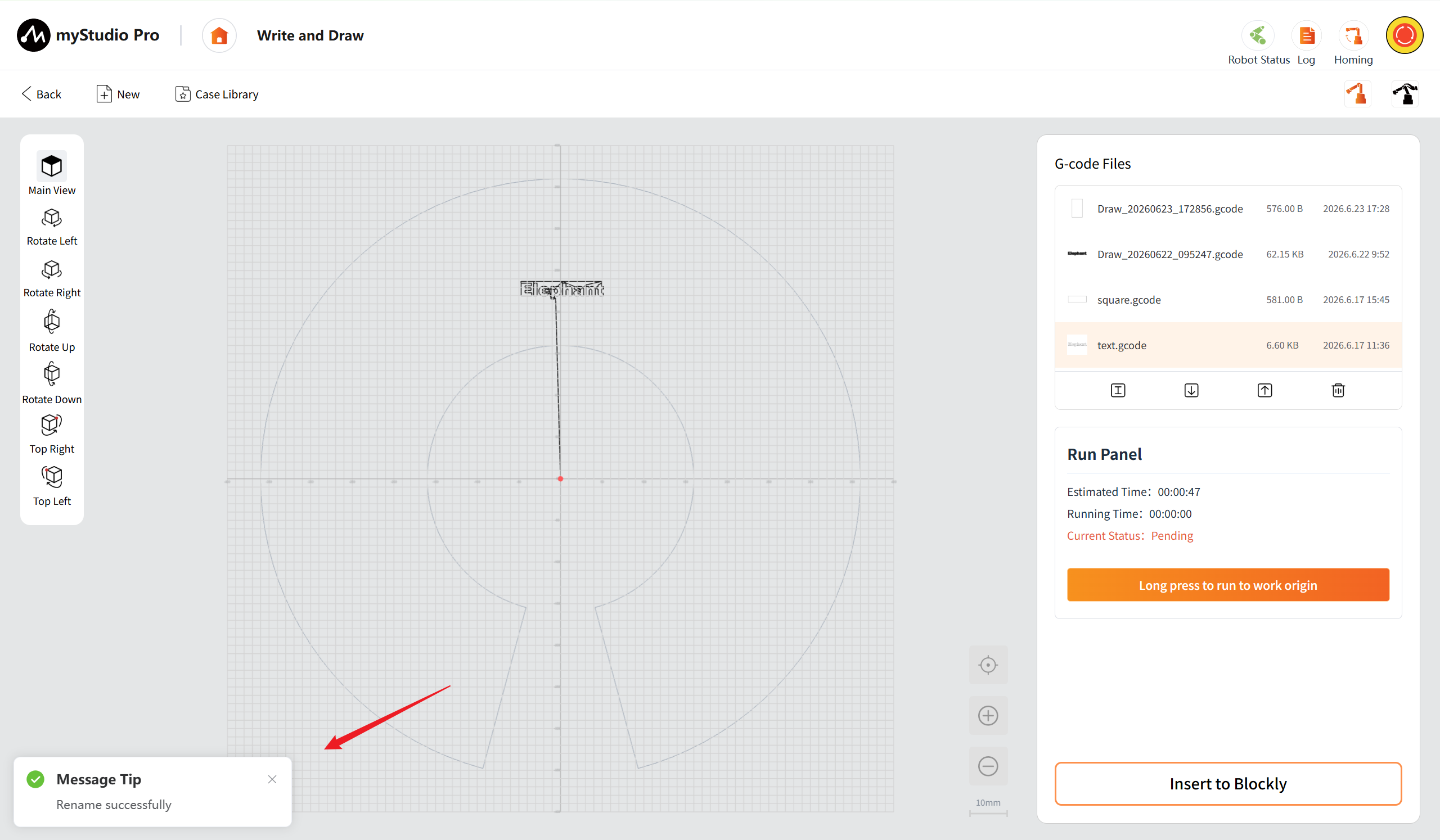
Rename: After selecting a list item, click the button to rename the file name of the list item.
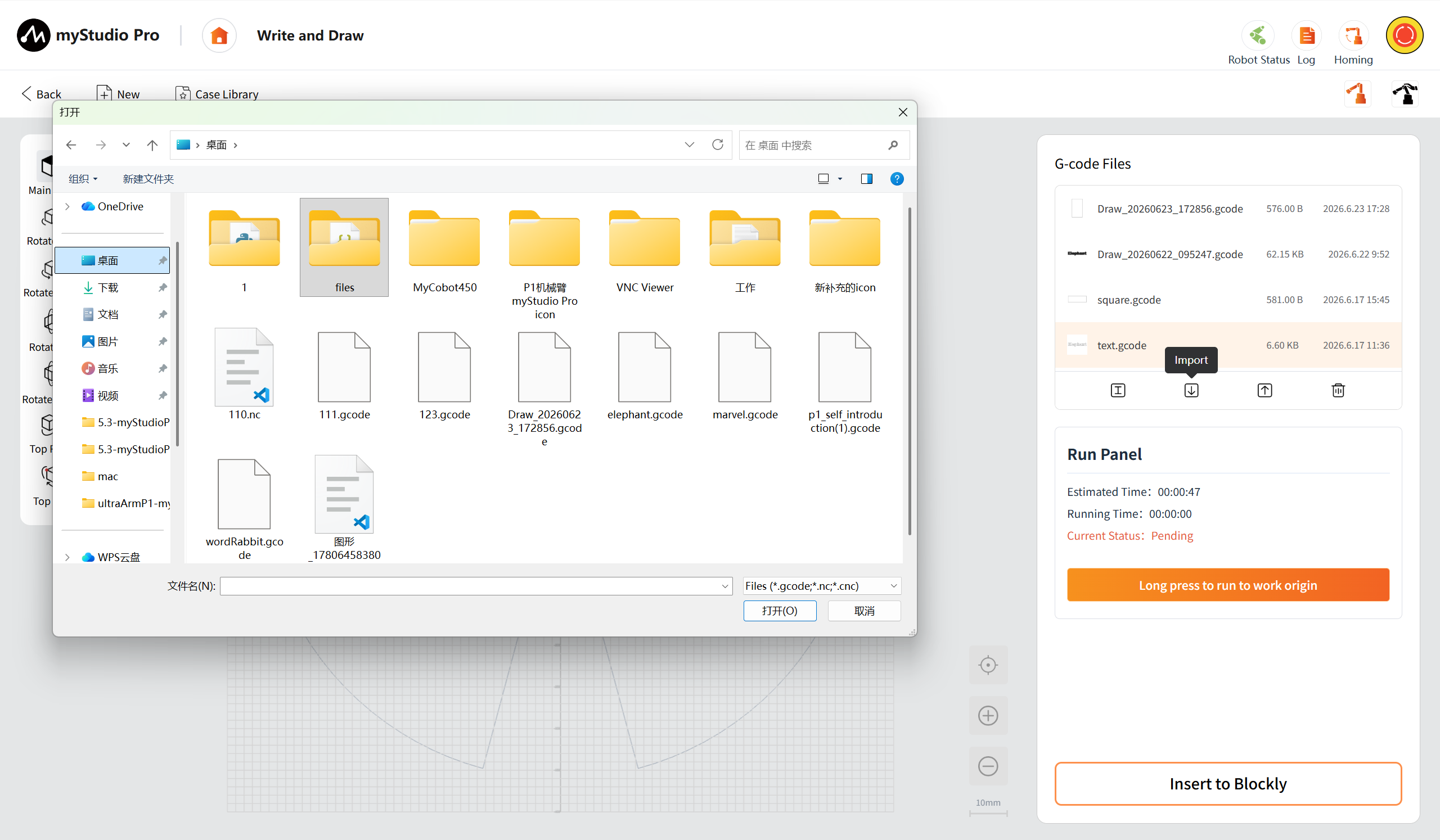
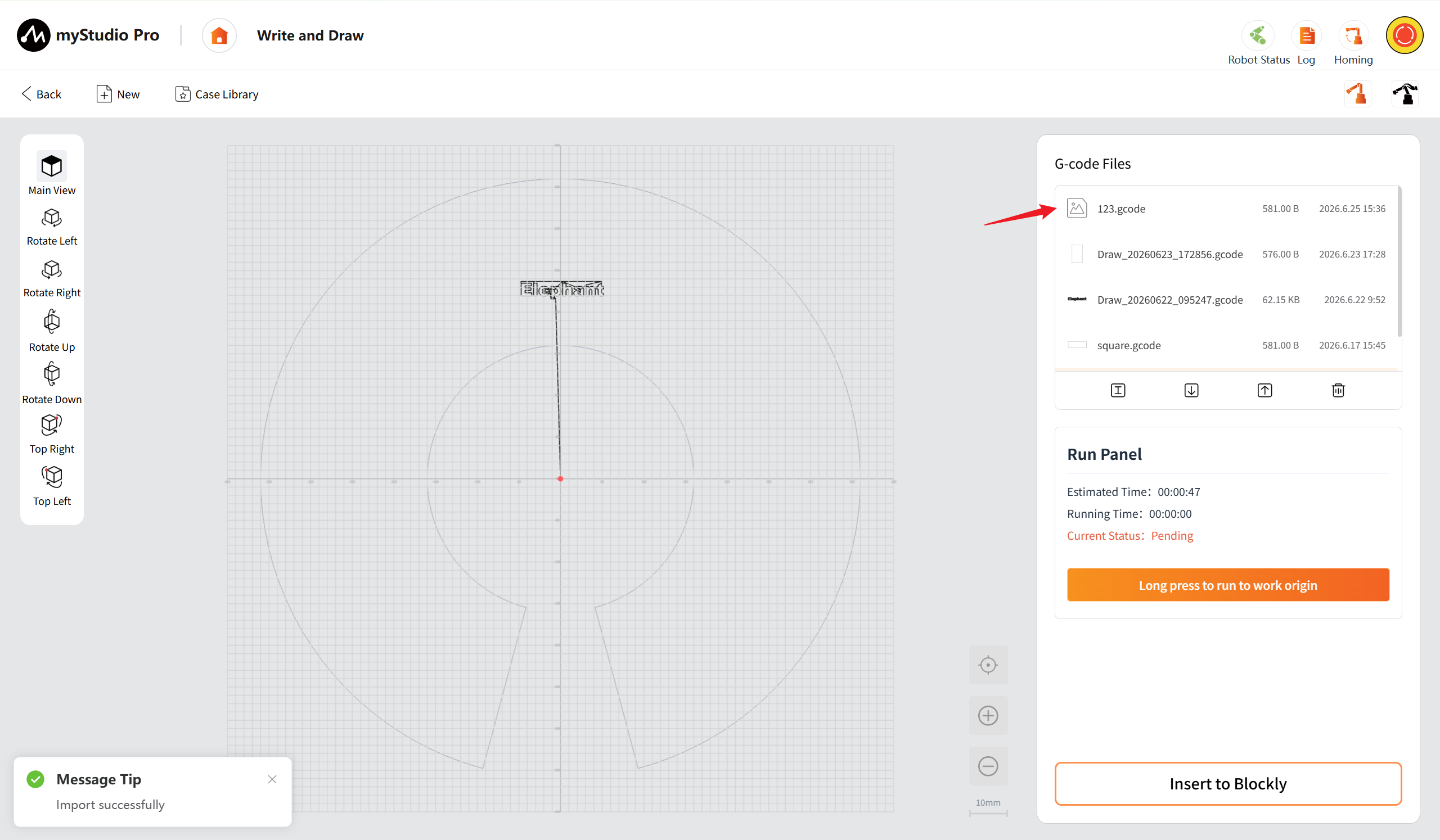
Import: After clicking the import button, you can import G-code files from your local device(Supports only.gcode, .nc, .cnc).
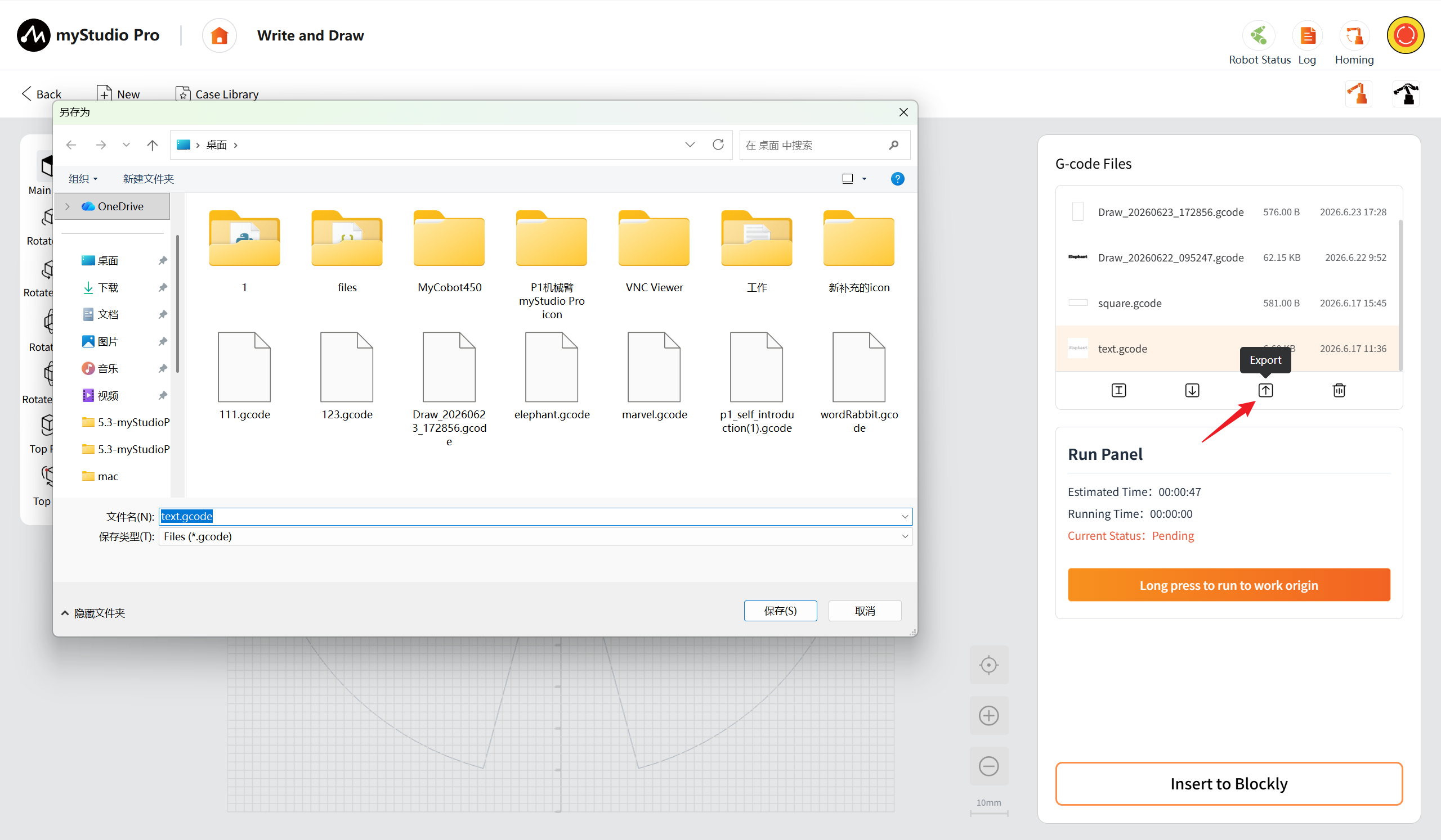
Export: After clicking the export button, you can export the selected file to your local device.
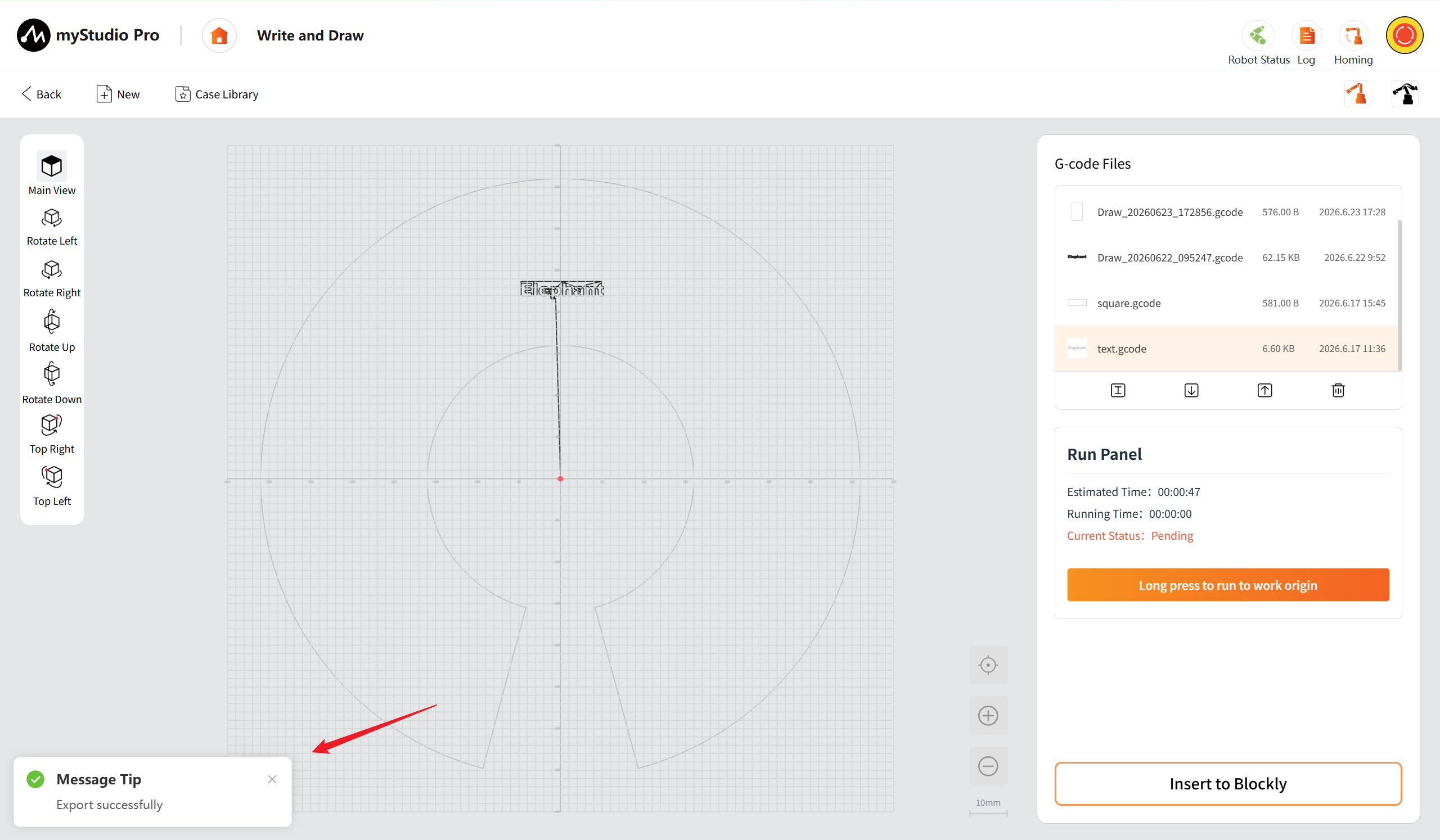
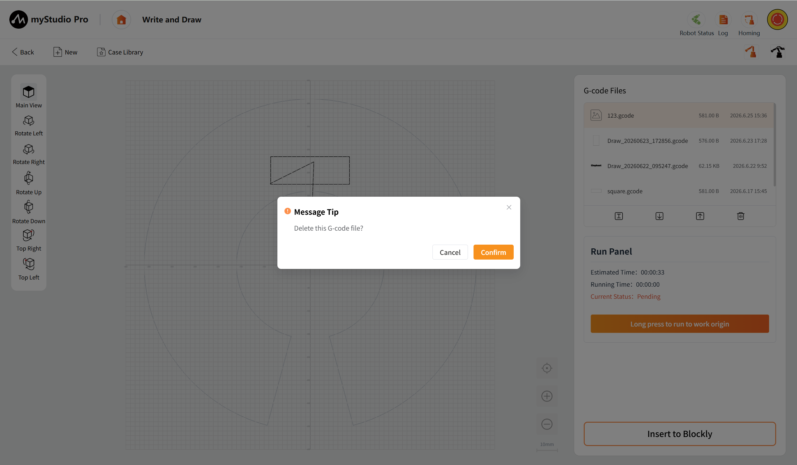
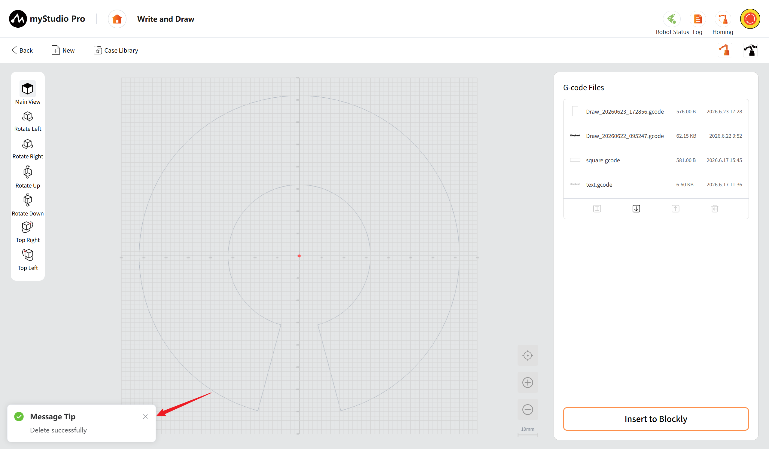
Deleted: After clicking the delete button, a pop-up window will appear. Confirm the operation and the selected files can be deleted. Click "Confirm" to delete.
Operation Panel
When the page is loaded, no G-code file is selected and the operation panel is in a hidden state. After a G-code file is selected, the operation panel for that G-code file is displayed.
Long press to run to work origin: After long pressing the button, the robotic arm will run to the preset work origin. Once it reaches the original position, the buttons for runn, pause, and stoppg will be displayed.
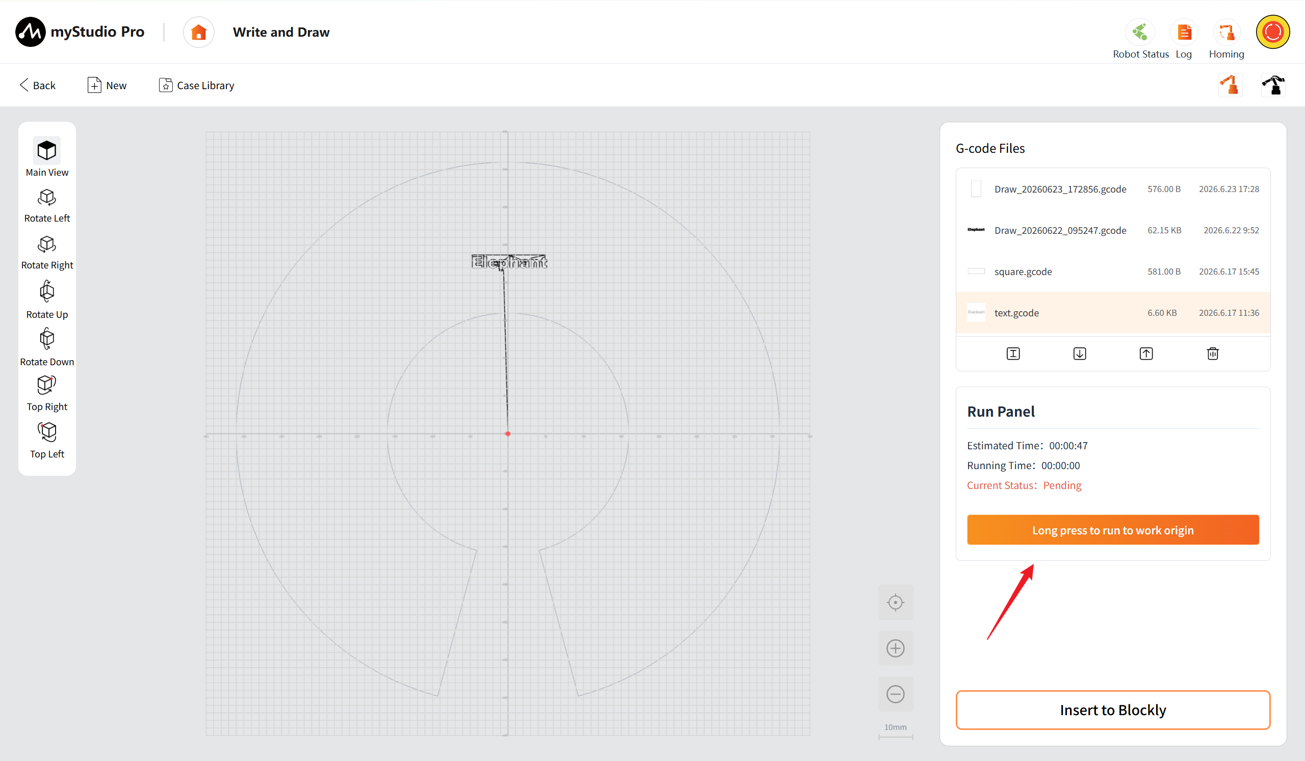
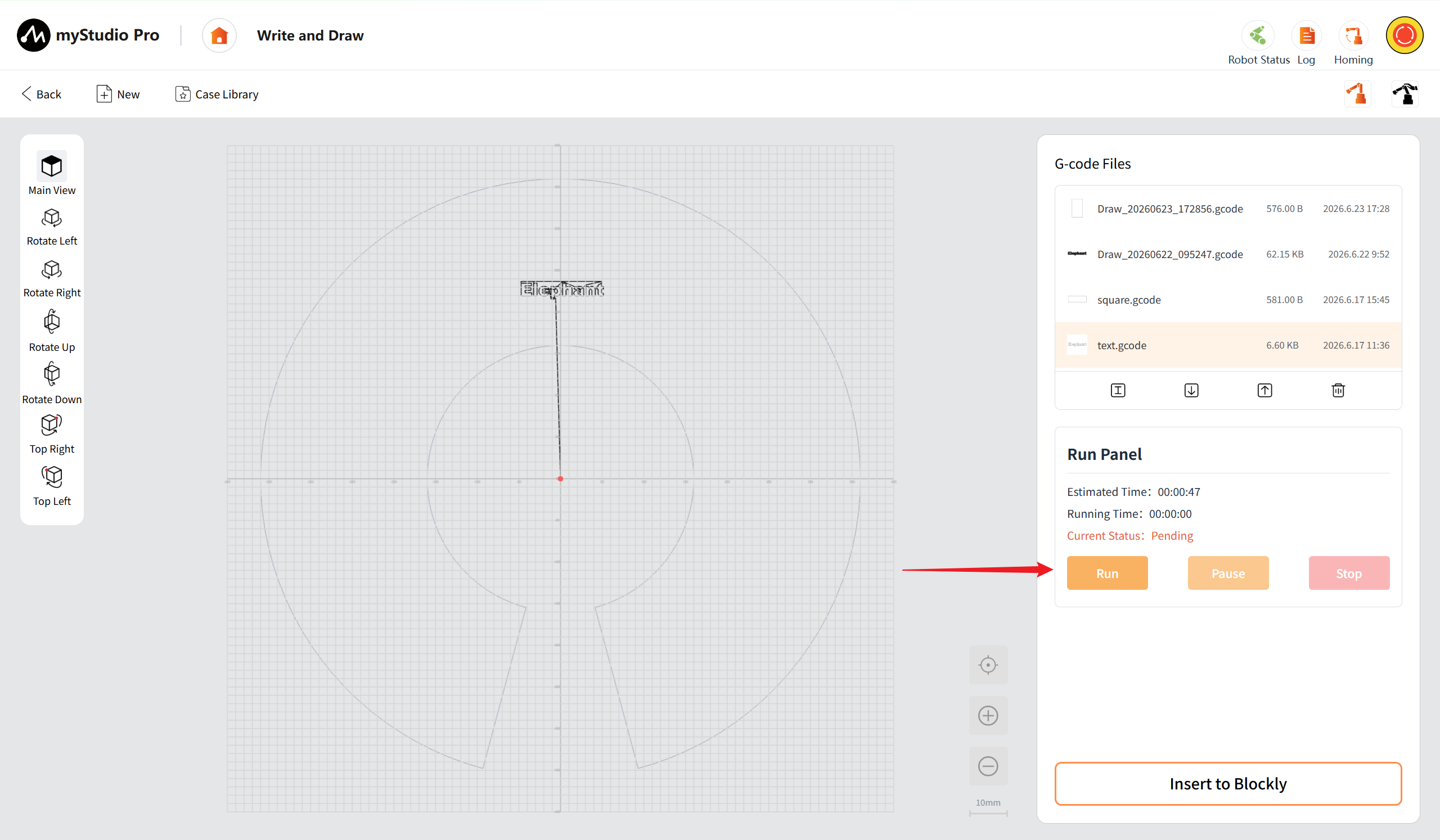
Run: After clicking the Run button, the robotic arm starts to process the file. The running time begins to be counted, the current status changes to "Running", the Run button turns to be disabled, while the Pause button and the Stop button become enabled.
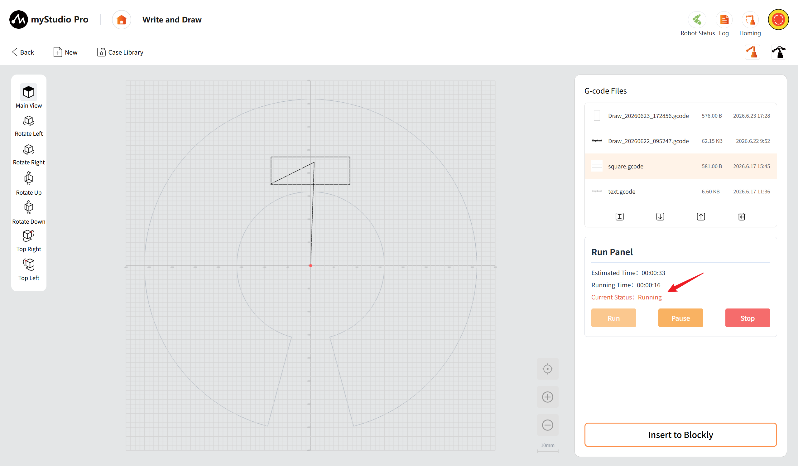
Pause: After clicking the pause button, the robotic arm stops running. The current status of the panel changes to "Paused", the run button becomes the "Resume" button, while the pause button becomes disabled and the resume button and stop button become enabled.
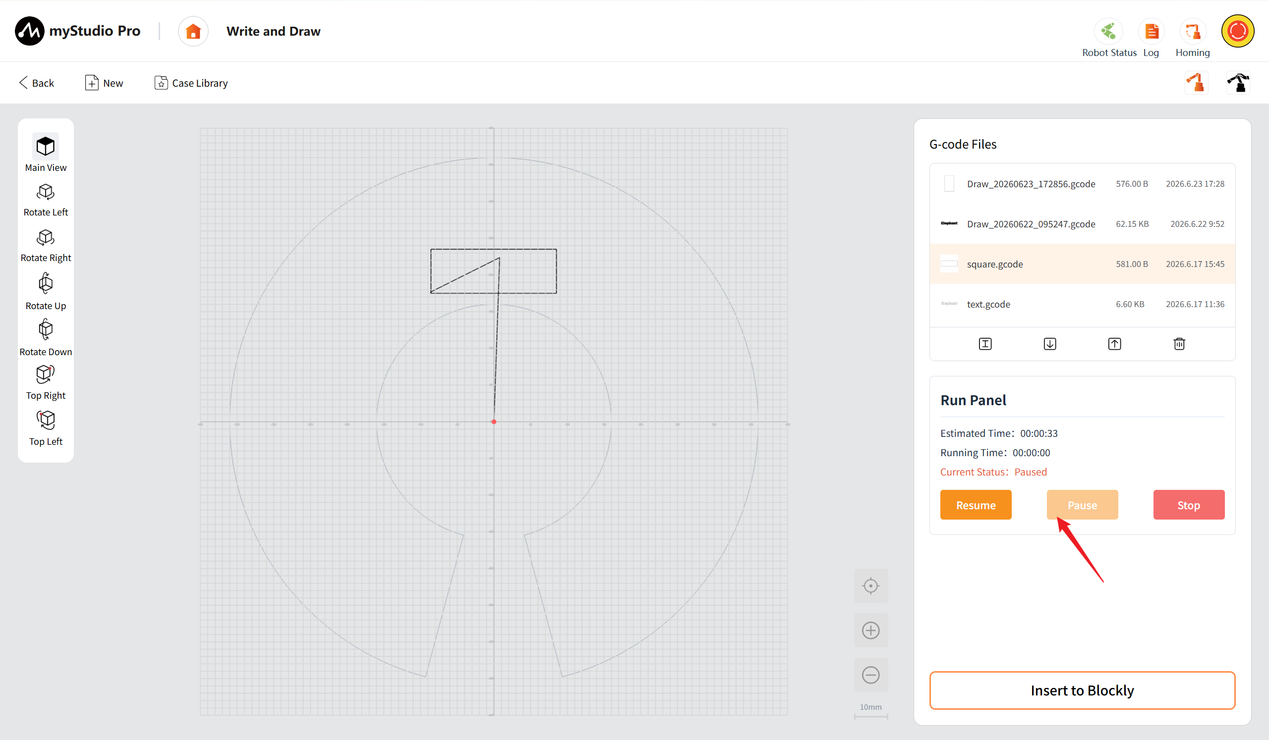
Resume: After clicking the "Resume" button, the robotic arm resumes its movement.
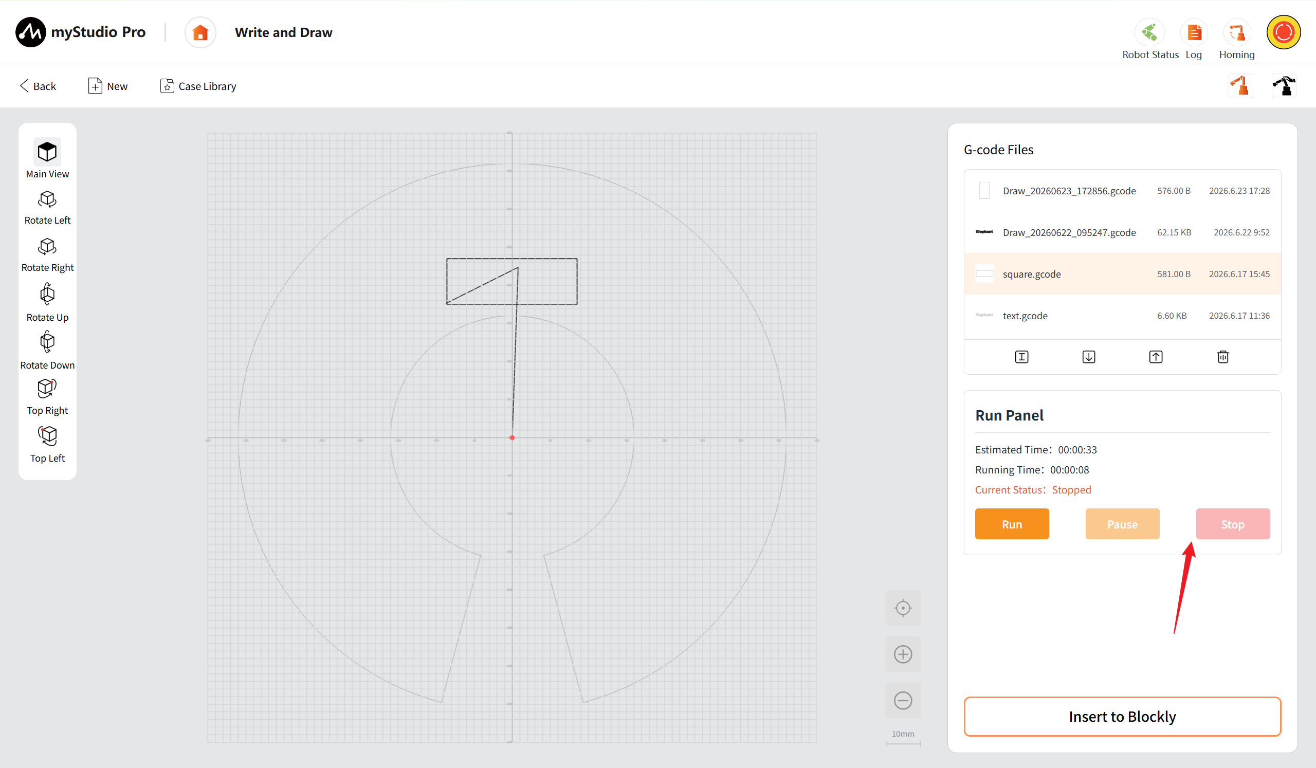
Stop: After clicking the stop button, the software stops issuing commands. The current status is "Stopped". Except for the Run button which is enabled, the pause button and the stop button are both disabled. The robotic arm will stop after completing the executed instructions. The current status of the operation panel is "Pending".
Insert into Blockly: After clicking the "Insert into Blockly" button, you will be redirected to the "Blockly Programming Workbench". You can achieve batch execution through block-based programming.
The Workbench
The writing and drawing workstation is the core interface for creating, editing, configuring parameters and executing tasks in pattern design.
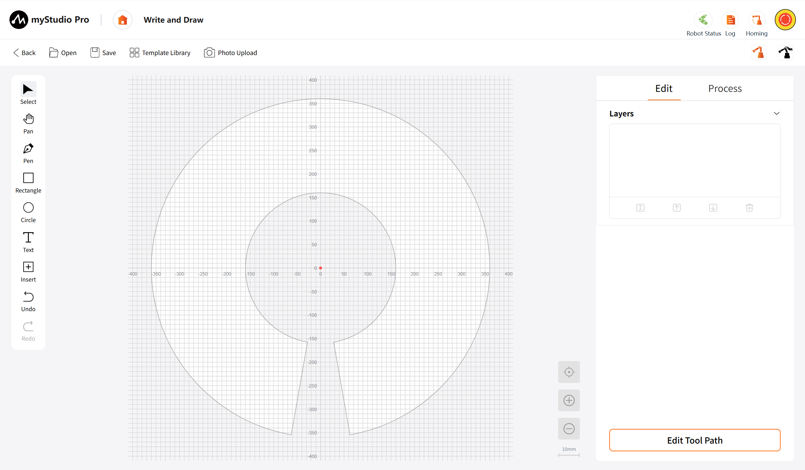
Top Toolbar
Project operations and material import include returning to the parent level, opening local projects, saving the current work, calling the built-in template library, and taking photos to upload images. This enables a complete process of operation from obtaining external resources to project file management. The point tool provides quick movement and free movement. After quick movement, a debugging pop-up window will appear, supporting the setting of the work origin, the starting point of the trajectory, and precise point position debugging; the free movement mode allows directly dragging the mechanical arm to the target point, simplifying the point position debugging process.
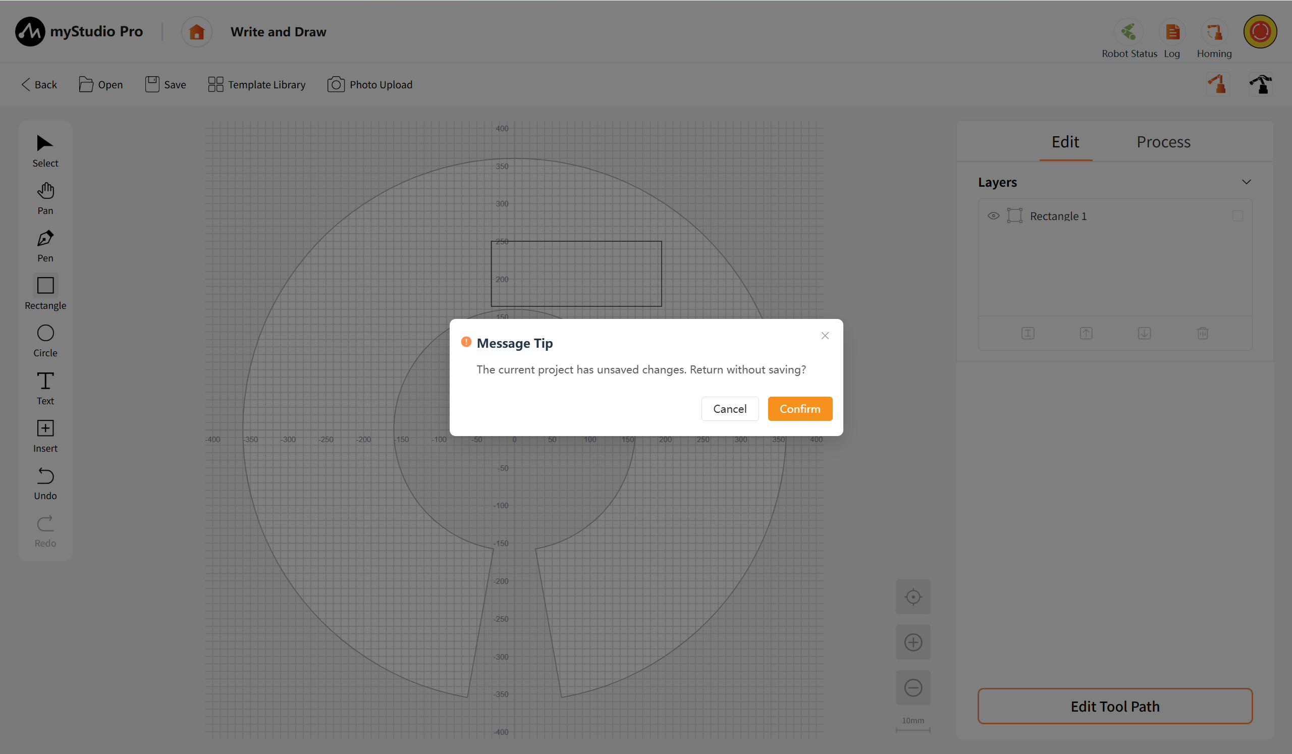
Back: Click the "Back" button to return to the "Scene Application main screen" of the previous level. If the current project has not been saved, the system will pop up a prompt box asking whether to return directly without saving. Click the "Confirm" button to return without saving, and click the "Cancel" button to close the prompt window and remain on the current editing page.
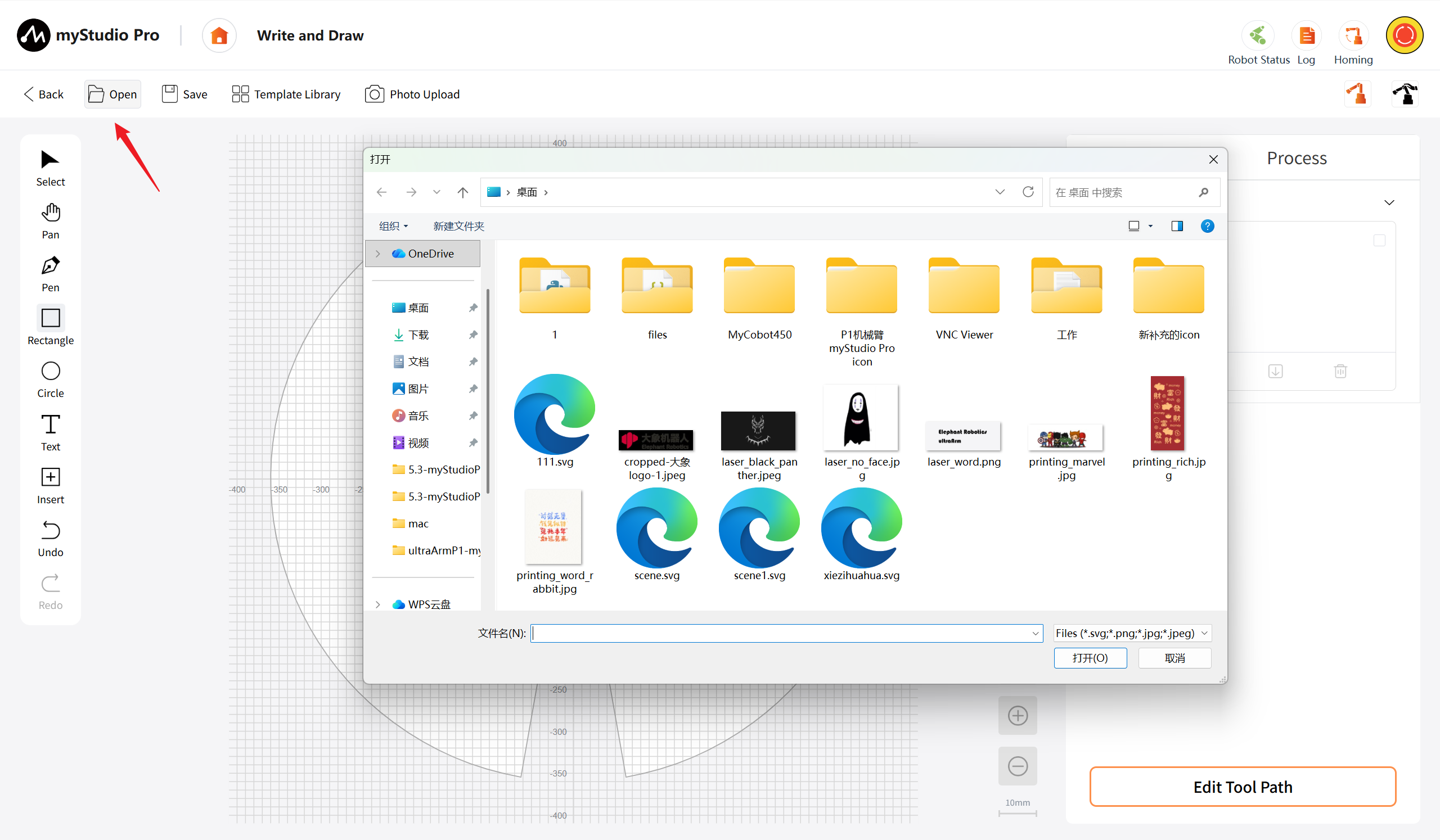
Open: Click the "Open" button, and a local file selection window will pop up. It supports the selection of project files (such as .svg, .png, .jpg, .jpeg) for import into the current workbench.
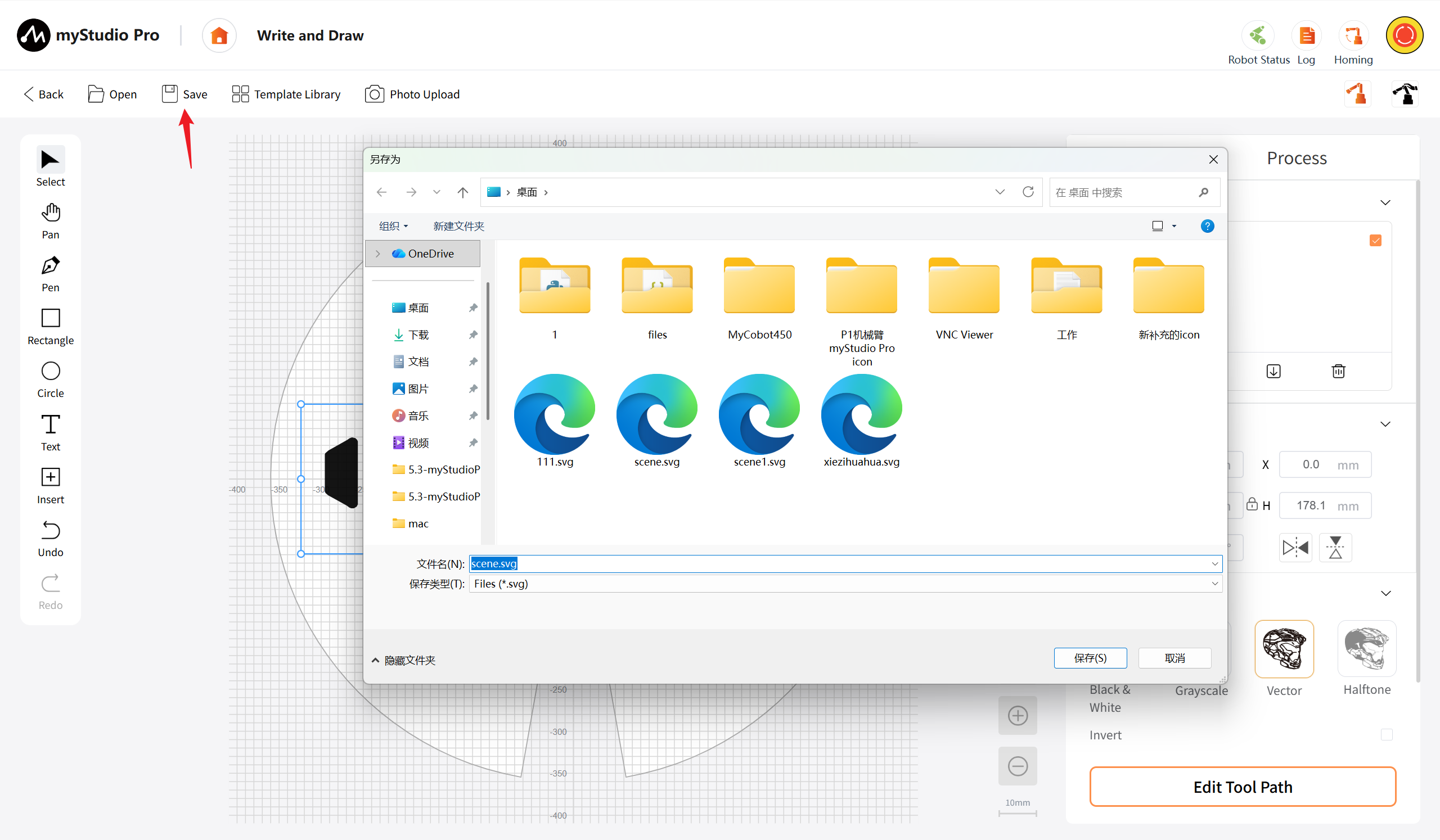
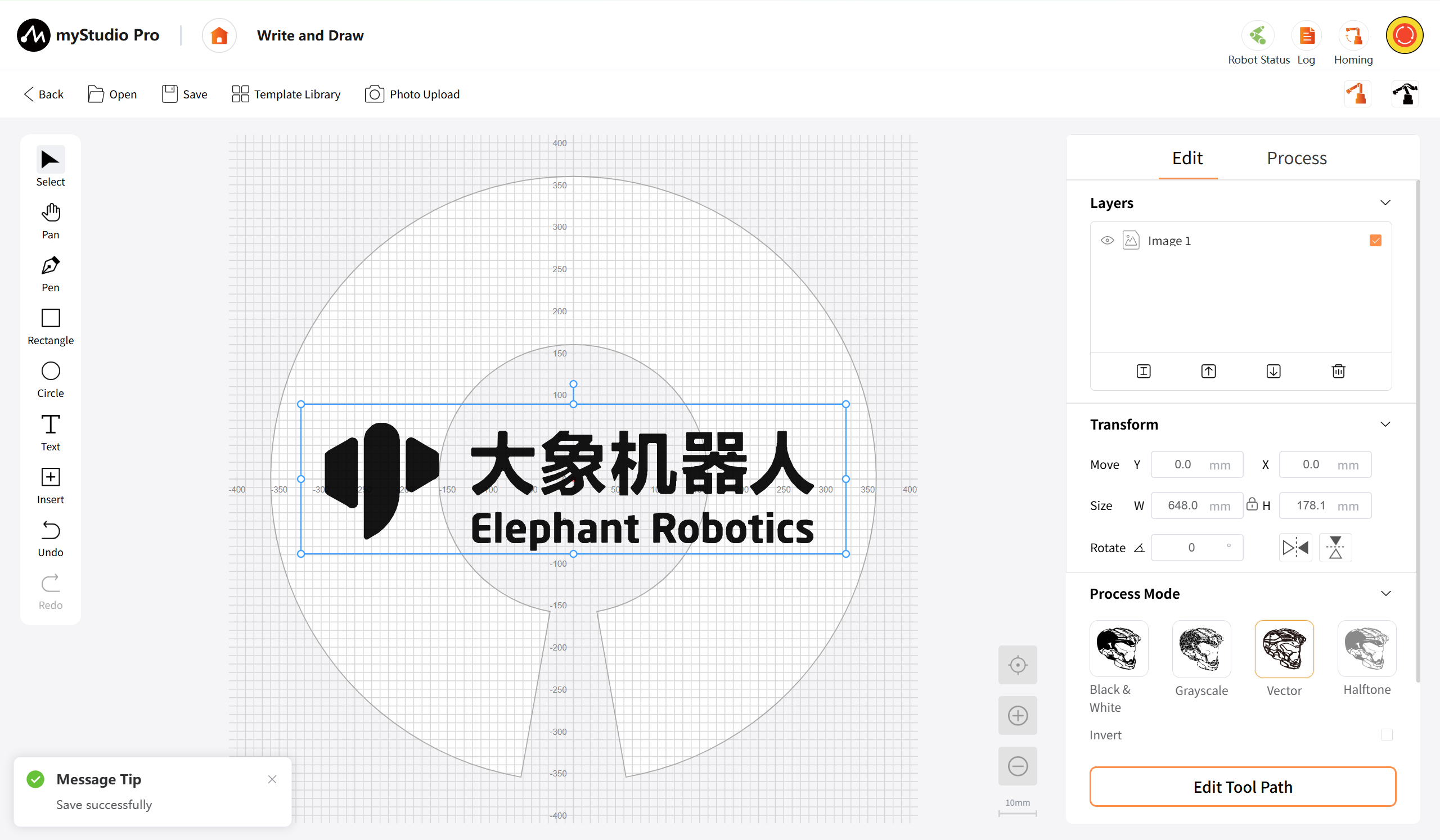
Save: Click the "Save" button to save the current pattern on the canvas as a project file. When saving for the first time (creating a new project), a local file saving window will pop up, allowing you to customize the file name and select the storage path. The default path is the software-specific directory, and the file format is.svg. Subsequent saves (if a corresponding file already exists) will directly overwrite the original file without displaying a window.
Template Library: Click the "Template Library" button, which will display a dropdown box. This box showcases the built-in preset patterns. After clicking any template, the system will automatically insert the template pattern at the center of the canvas and keep it selected for further editing.
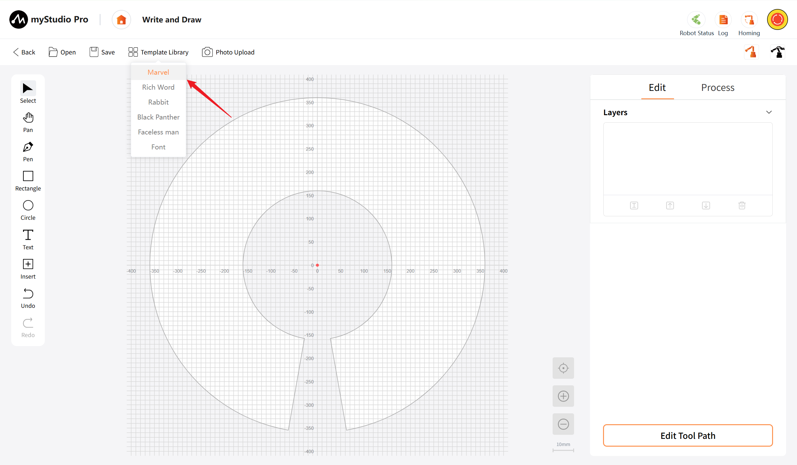
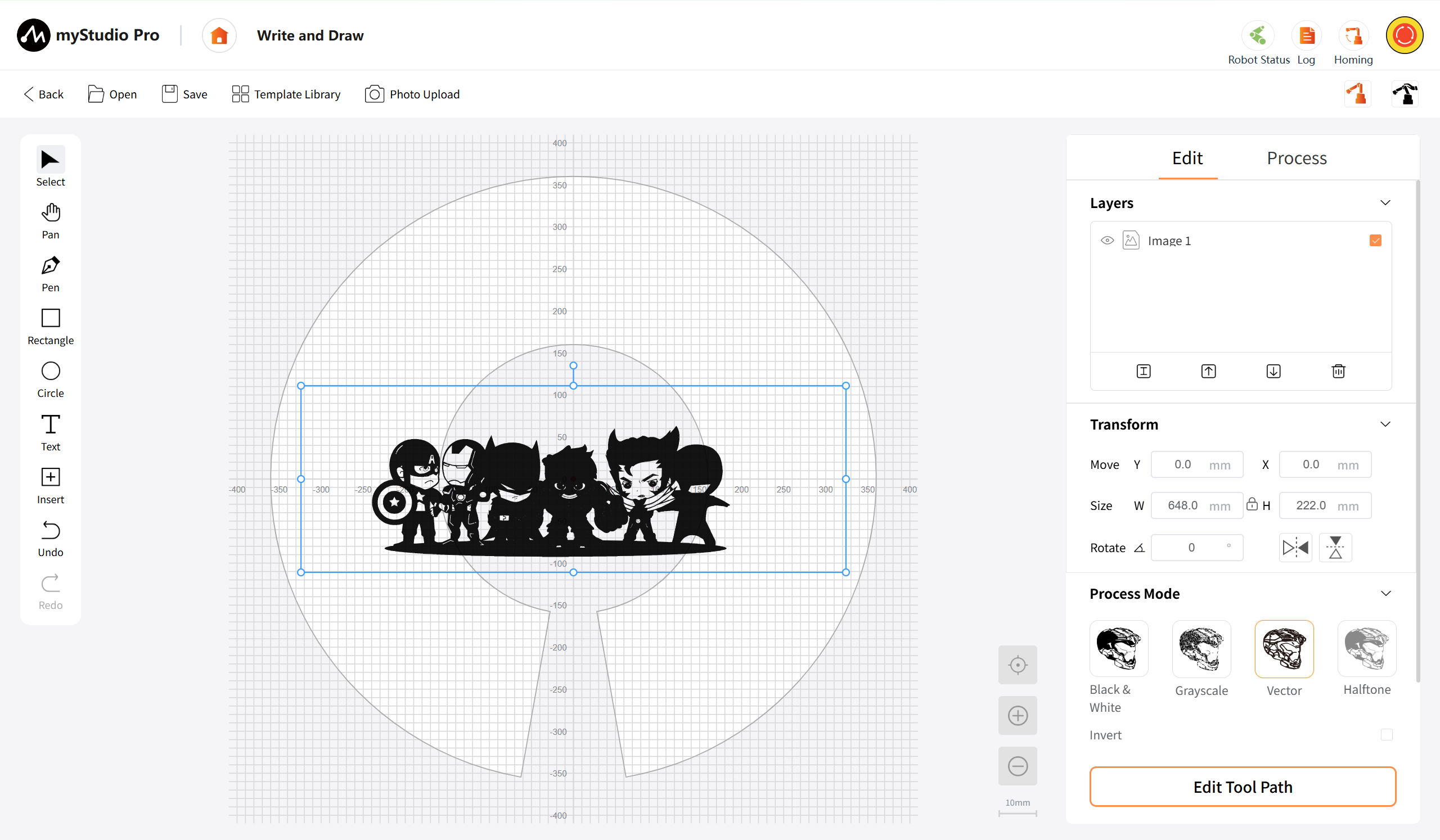
Photo upload : Under development.
Quick Movement: Click the button to open the Quick Movement Page.
Free Movement: : When clicked, a message box will pop up. After confirming, the robotic arm can be manually dragged and moved to the initial position, simplifying the debugging process.
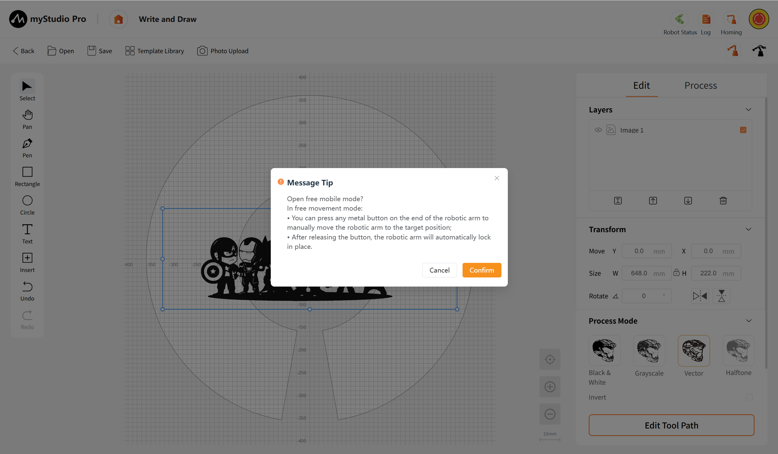
Left Toolbox
Comprises the core tools for graphic drawing and editing, offering object selection, canvas movement, pen drawing, circle drawing, text addition, insertion of preset graphics, as well as undo and redo functions. The undo and redo operations support shortcut key operations (Ctrl+Z/ Ctrl+Y), facilitating users to quickly revert or restore editing steps.
Select: Used to select graphic objects on the canvas. It supports single-click selection of individual graphic objects, or dragging the mouse to select multiple objects. After selecting an object, the color of the graphic object changes to blue, and editing operations such as moving, scaling, and rotating can be performed. Holding down the Shift key allows for continuous selection of multiple objects.
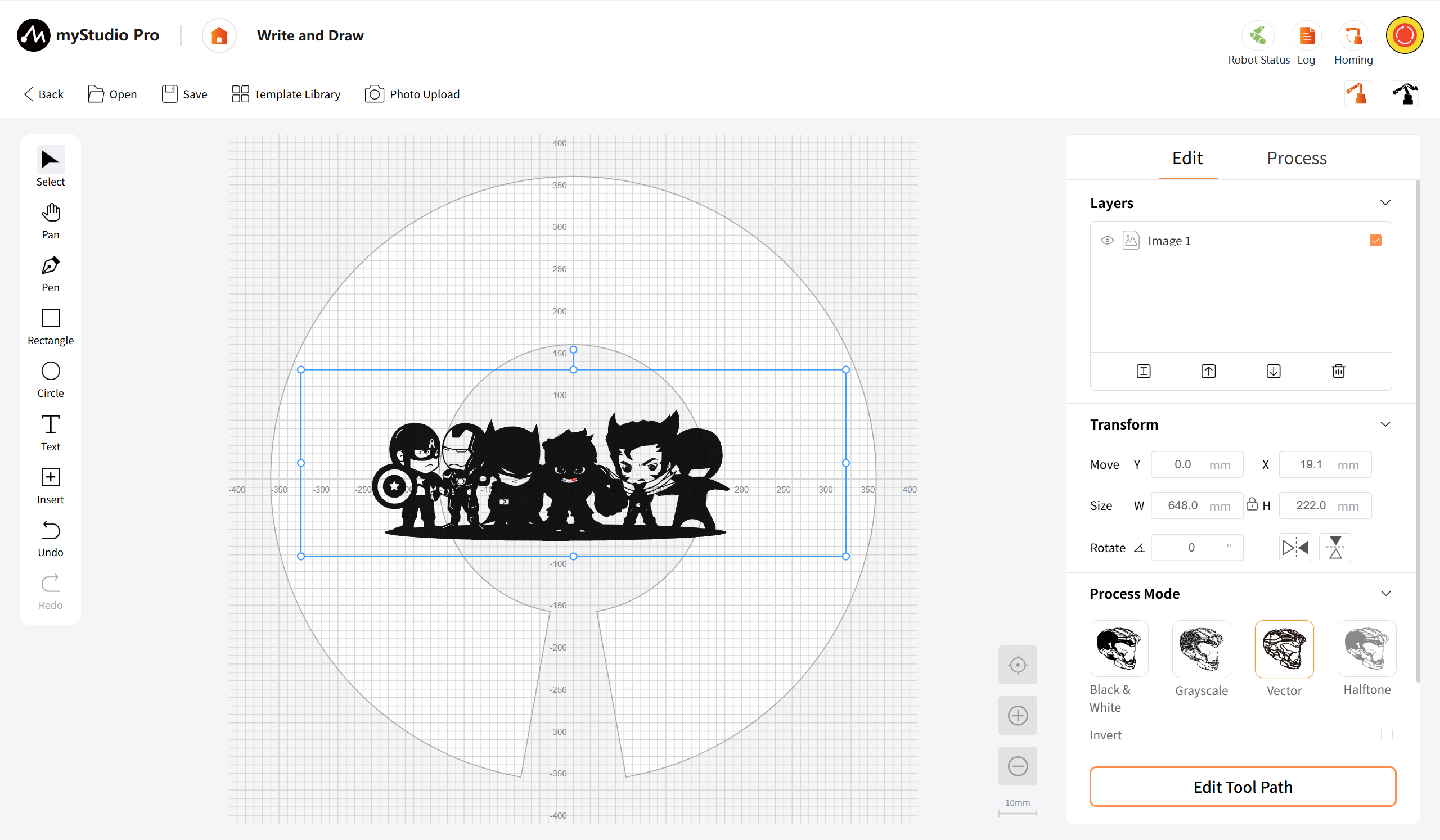
Pan: This function allows you to drag and shift the canvas perspective, facilitating the observation of different areas on the canvas.
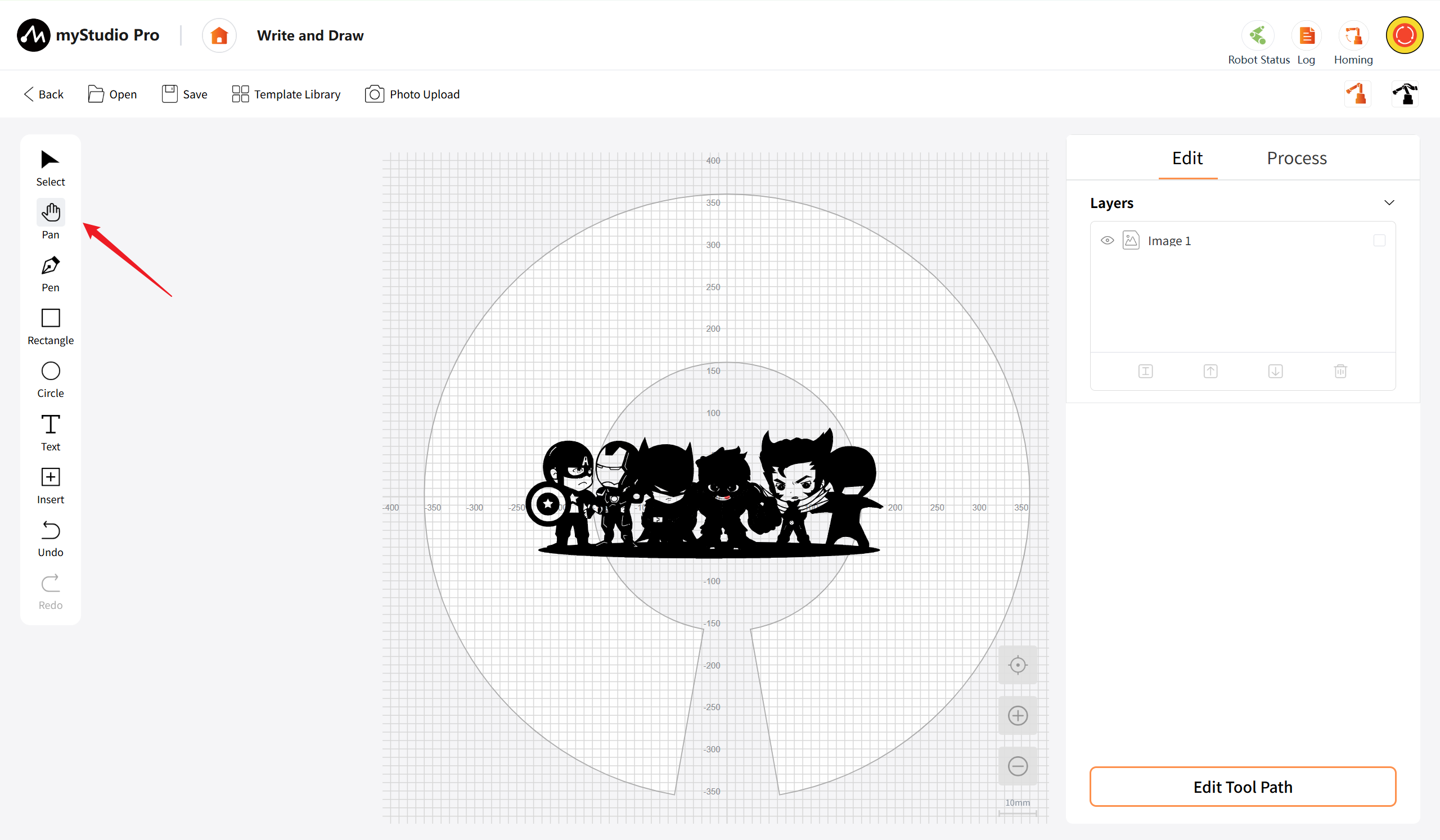
Pen: Used for drawing free curves or Bezier paths. Click the "Finish" button to end the current drawing.
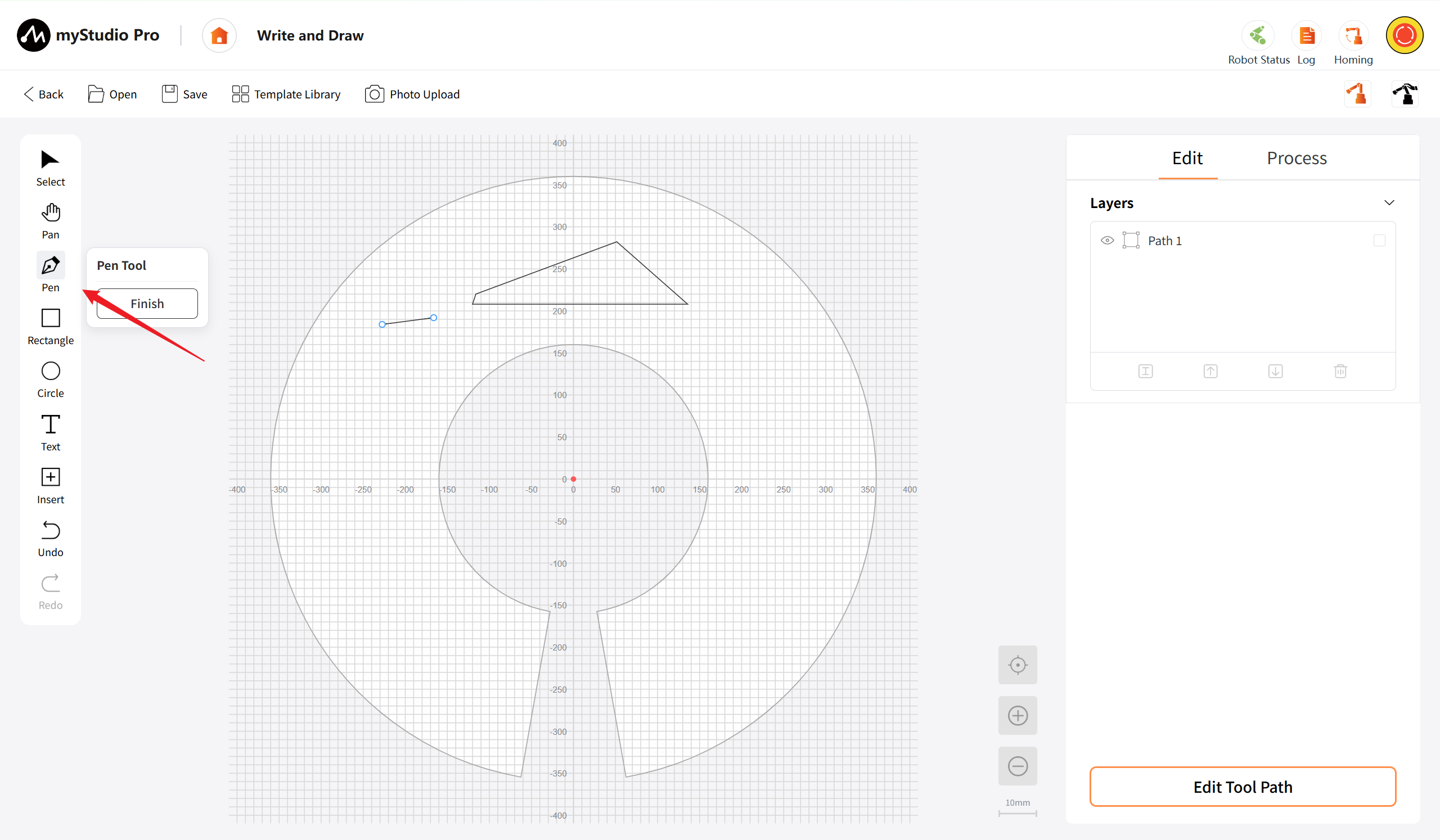
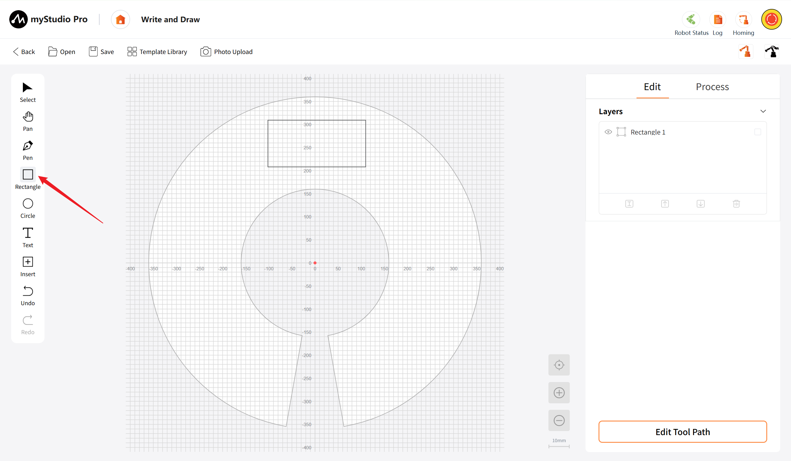
Rectangle: This tool is used to draw rectangular shapes. Simply hold down the left mouse button on the canvas and drag to create a rectangle. Release the mouse button to complete the drawing. Holding down the Shift key while dragging will allow you to draw a square.
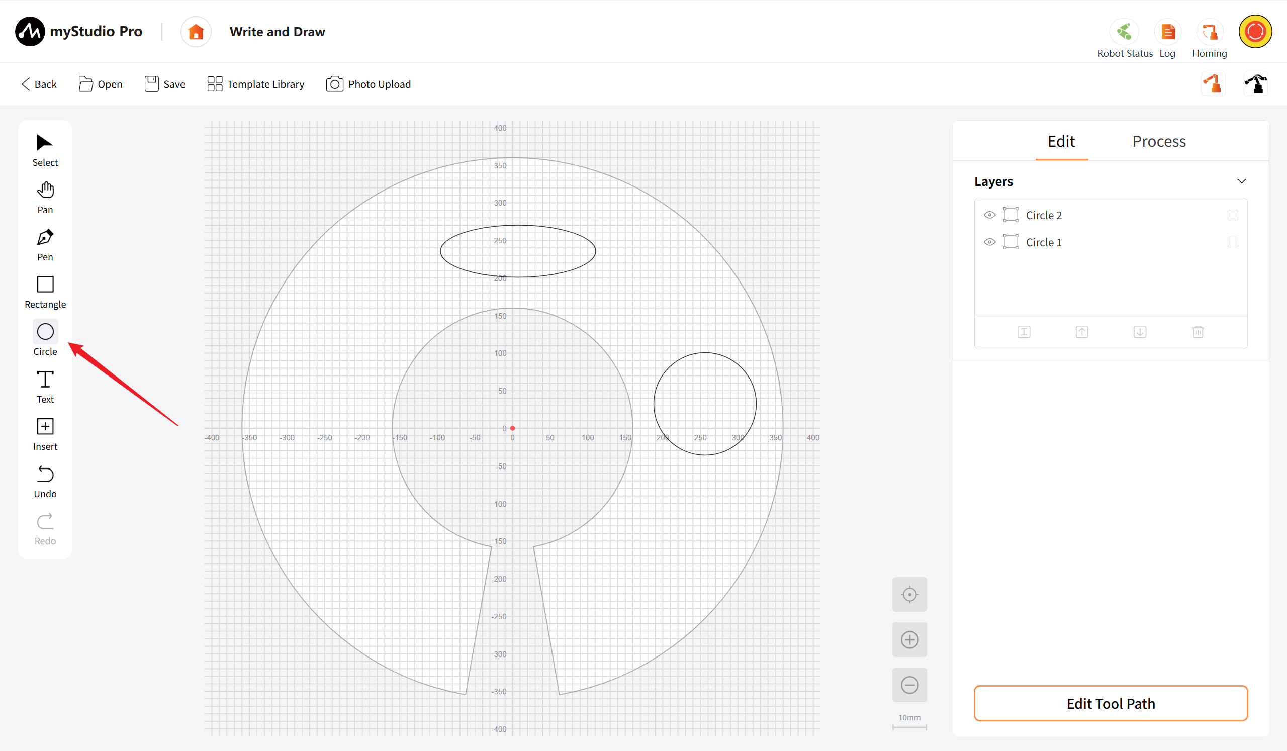
Circular: This tool is used to draw circular or elliptical shapes. Simply hold down the left mouse button on the canvas and drag to create an ellipse. Release the mouse button to complete the drawing. Holding down the Shift key while dragging allows you to draw a perfect circle.
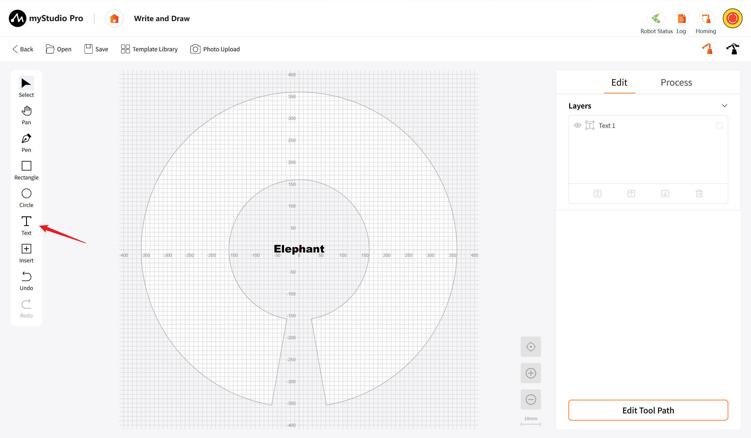
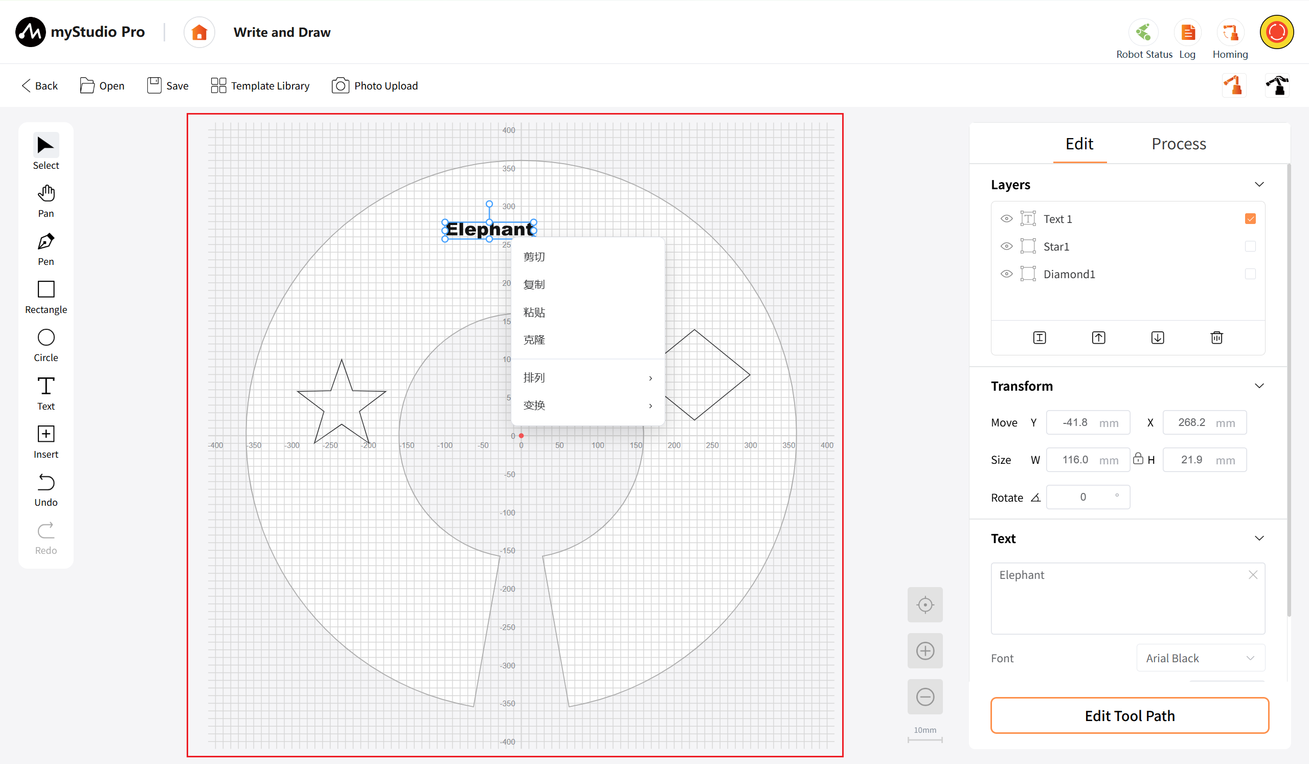
Text: This tool is used to add text objects onto the canvas. By clicking on the canvas, a text input box will appear. You can input Chinese or English text. After inputting, click outside the box to confirm. The generated text object supports subsequent editing of text content, setting of font, font size and other attributes.
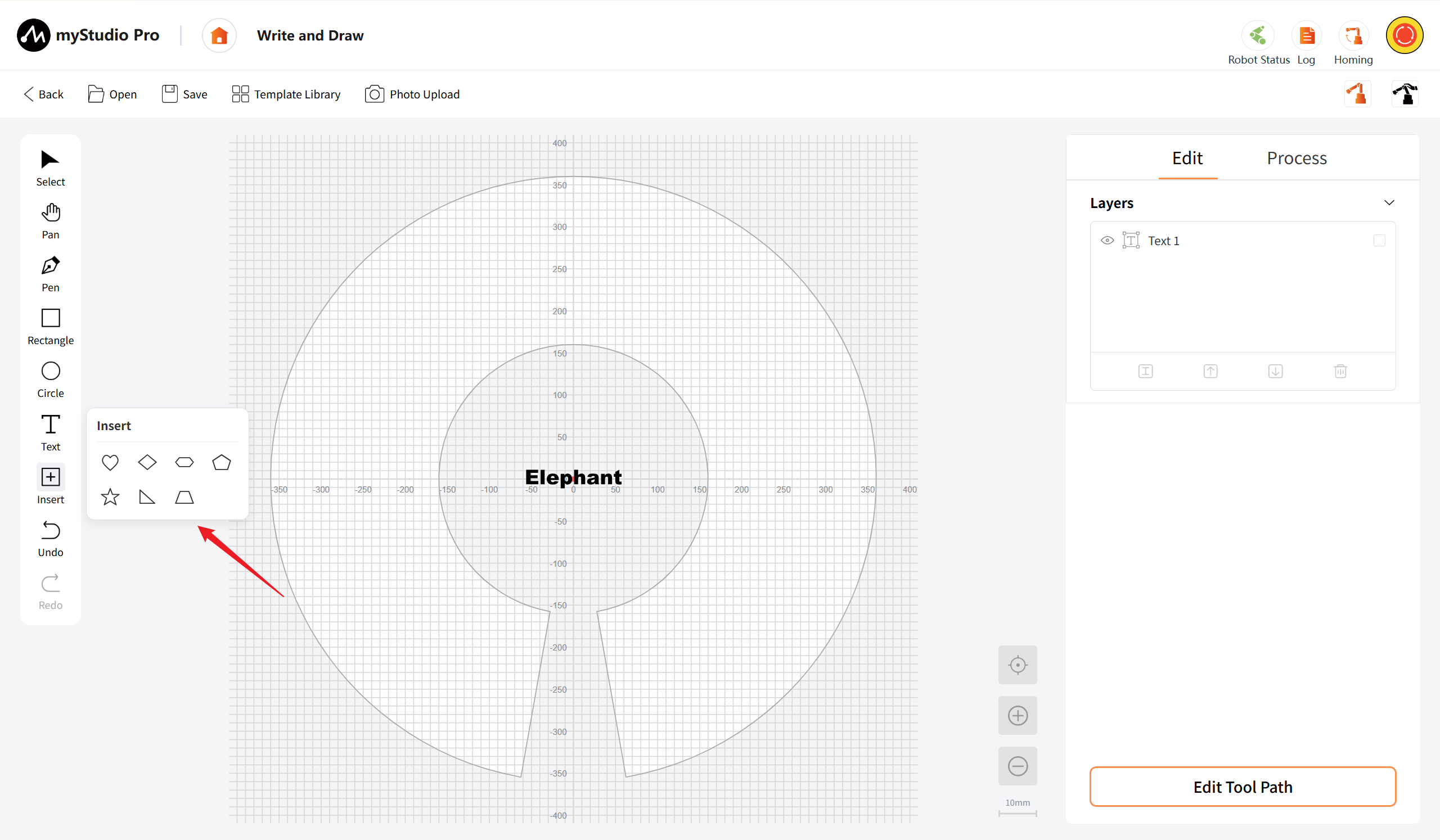
Insert: Used for inserting preset graphics. After clicking, a preset graphic selection panel will pop up, containing common shapes such as heart shapes, rhombuses, hexagons, pentagons, five-pointed stars, triangles, and trapezoids.
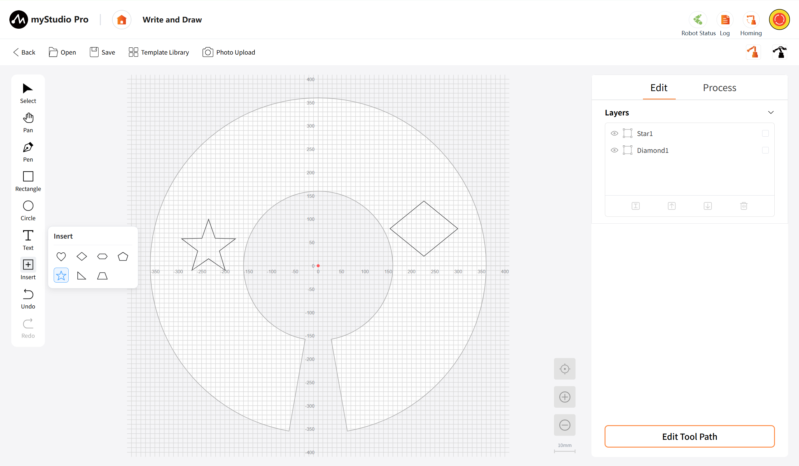
Undo: This is used to revert the previous editing operation. It supports continuous undo, allowing you to go back up to 50 historical operations. Additionally, it supports the shortcut key Ctrl+Z to quickly trigger the undo function.
Redo : Used to restore an operation that has been revoked. It can only be triggered after an undo operation has been performed. It supports continuous reversion until the latest state is restored. Additionally, it supports the shortcut key Ctrl+Y to quickly trigger the reversion function.
Canvas
The core display area, visually presenting the actual processing boundary of the robotic arm in a circular shape, hosting the display and basic interaction of the current edited graphic objects, supporting view operations such as canvas calibration and zooming, facilitating users to observe and edit the pattern from different scales.
The sector-shaped area represents the actual processing area for the robotic arm. The right-click of the mouse can access the tool menu.
Axis icon: It has no actual interactive effect; it merely serves as a coordinate axis indication: marking the X-axis and Y-axis.
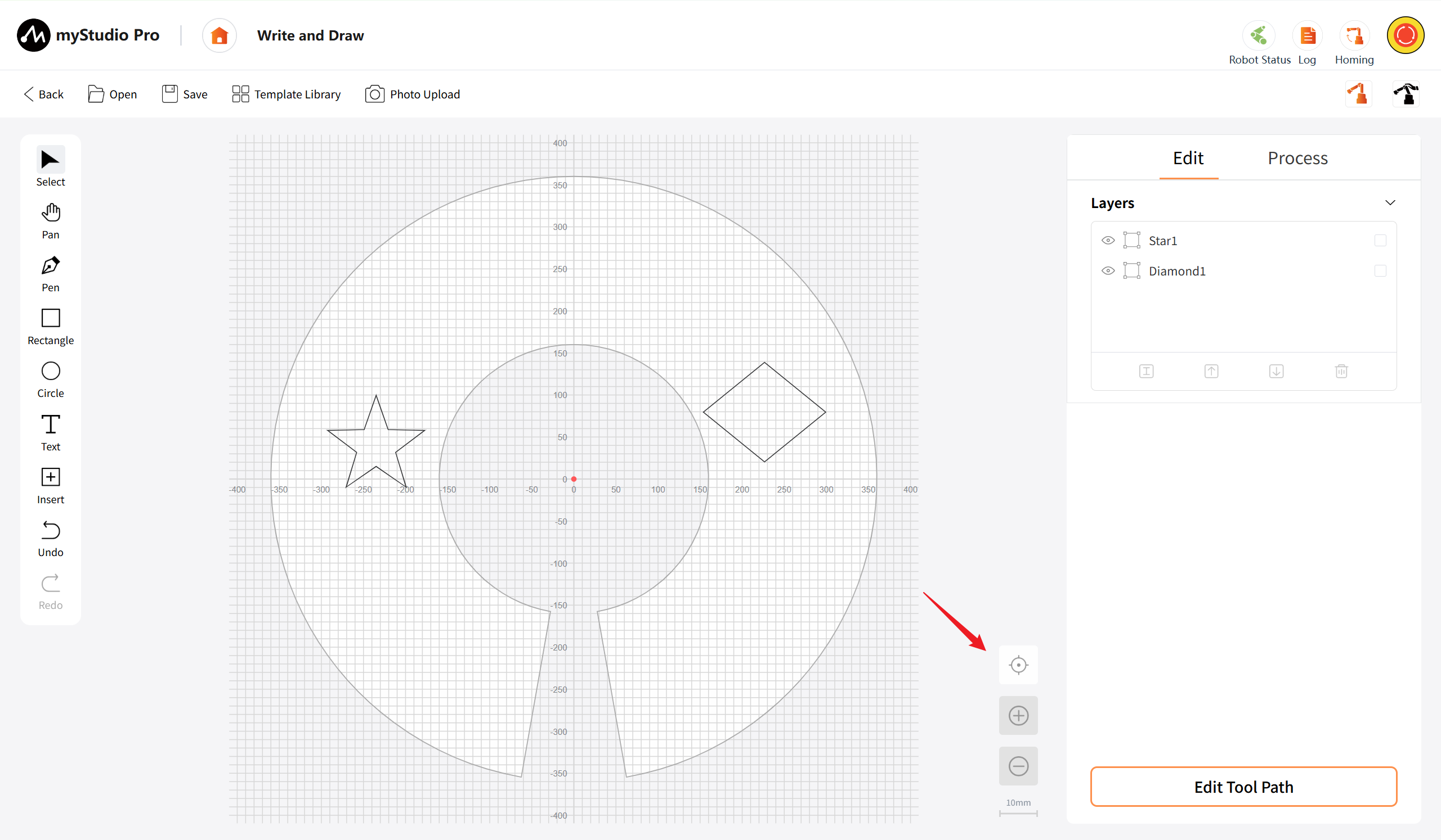
Calibration: Click the button to restore the canvas view to the default centered perspective, that is, the center of the canvas (0, 0). Align the view center, and the zoom ratio is restored to the default value (10mm/box).
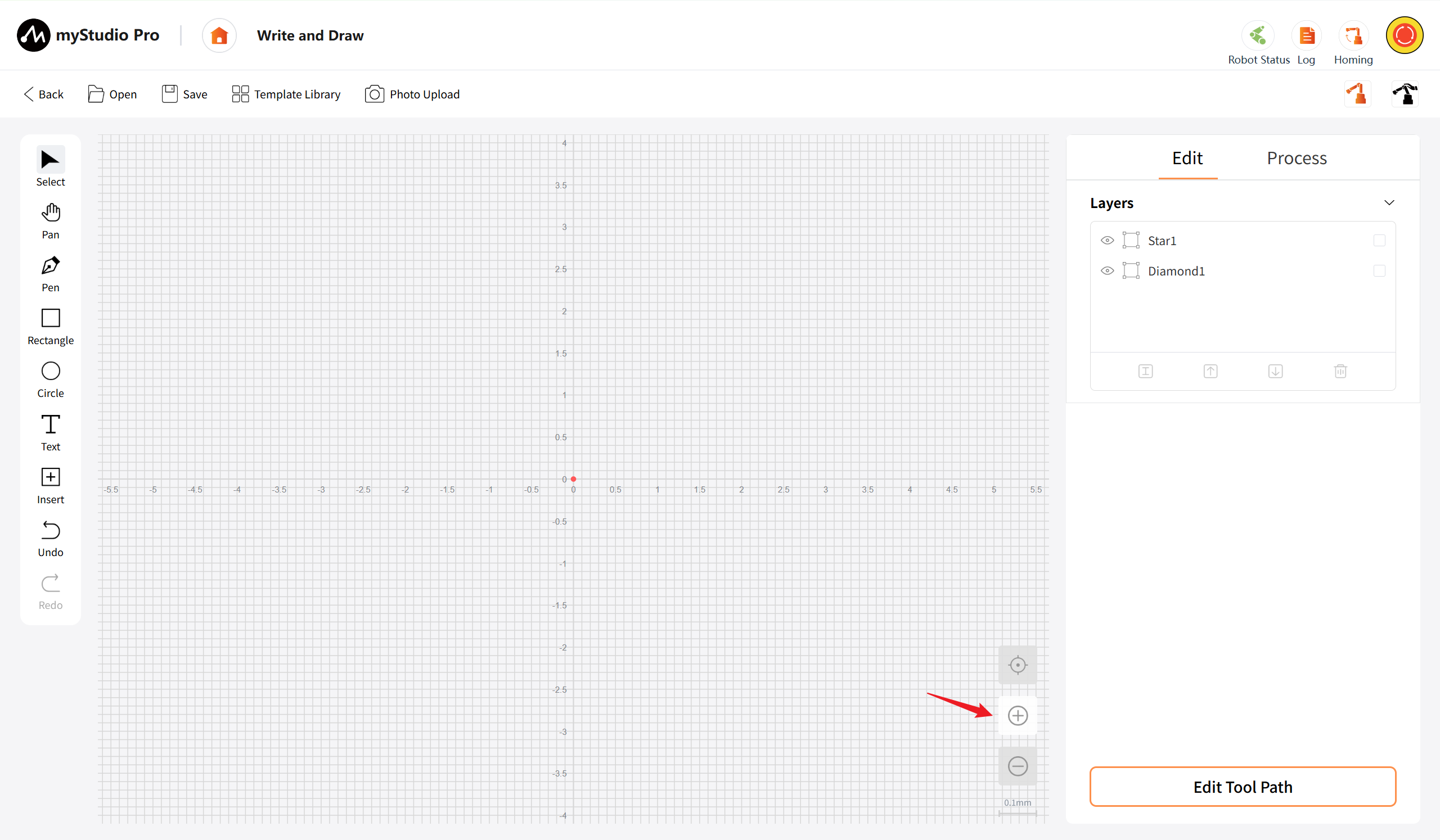
Zoom In: Click the zoom in button once to enlarge the canvas view by one level. The scale bar will switch to a smaller value according to the preset sequence (for example, from 10mm/interval to 5mm/interval). Support for continuous clicks to gradually zoom in to the minimum scale of 0.1mm/interval. Once the minimum scale is reached, clicking the button will have no effect.
Zoom Out: Click the "Zoom Out" button once to reduce the canvas view by one level. The scale will switch to a larger value according to the preset sequence (for example, from 10mm/interval to 20mm/interval). Support for continuous clicks to gradually zoom out to the maximum scale of 100mm/interval. Once the maximum scale is reached, clicking the button will have no effect.
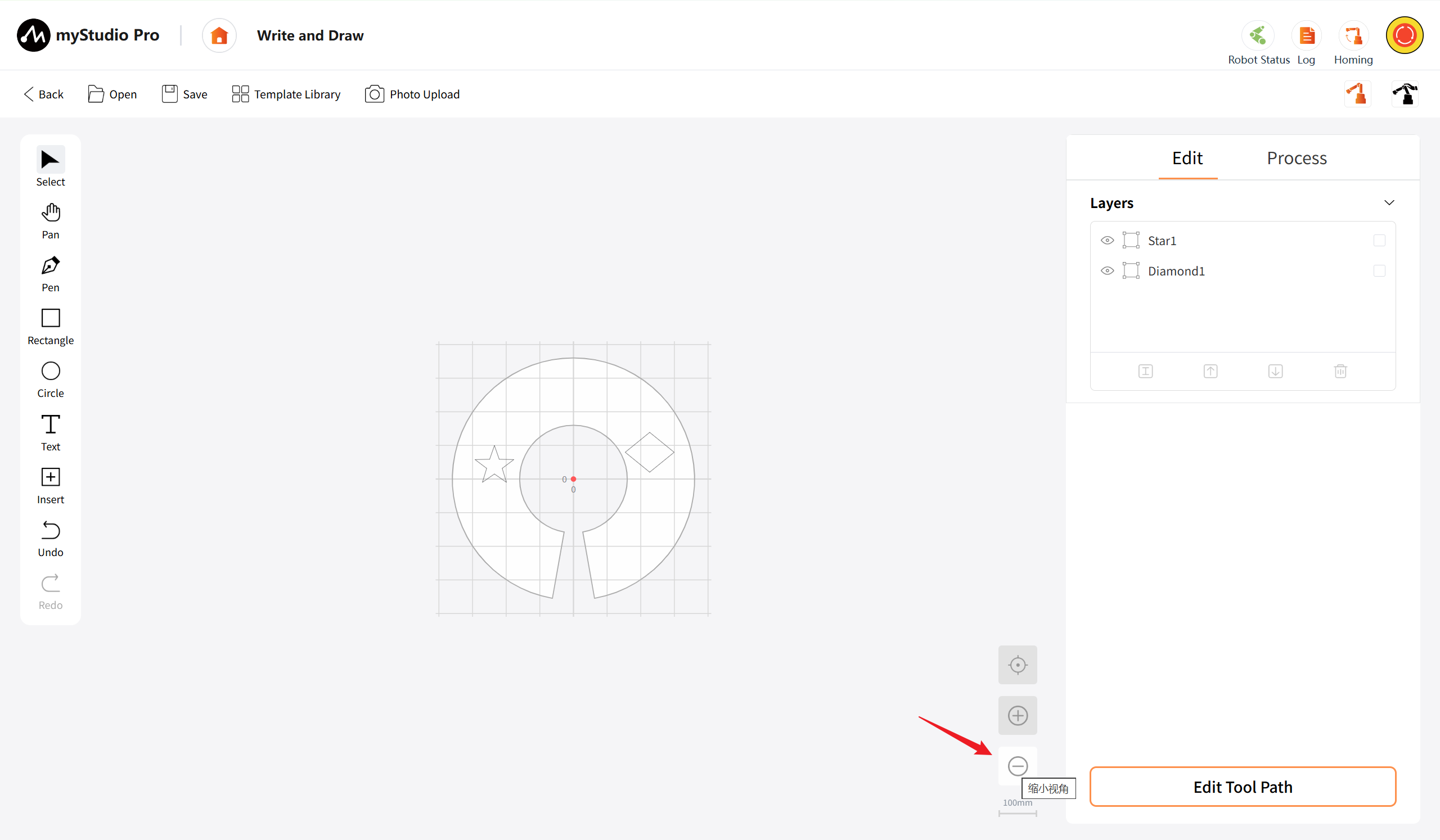
Scale display: The current scale is shown in the lower right corner of the canvas.
Right-hand Attribute Panel
As the core area for graphic attribute configuration and processing preparation, it features two functional modules: tab switching for editing and processing. The editing module supports layer management (renaming, level adjustment, deletion) as well as adjustment of transformation attributes for graphic objects (coordinates, dimensions, text, and image processing modes); the processing module enables selection of graphic objects and creation of tool paths, leading to the subsequent configuration of processing parameters and generation of G-code, achieving seamless transition from design to processing.
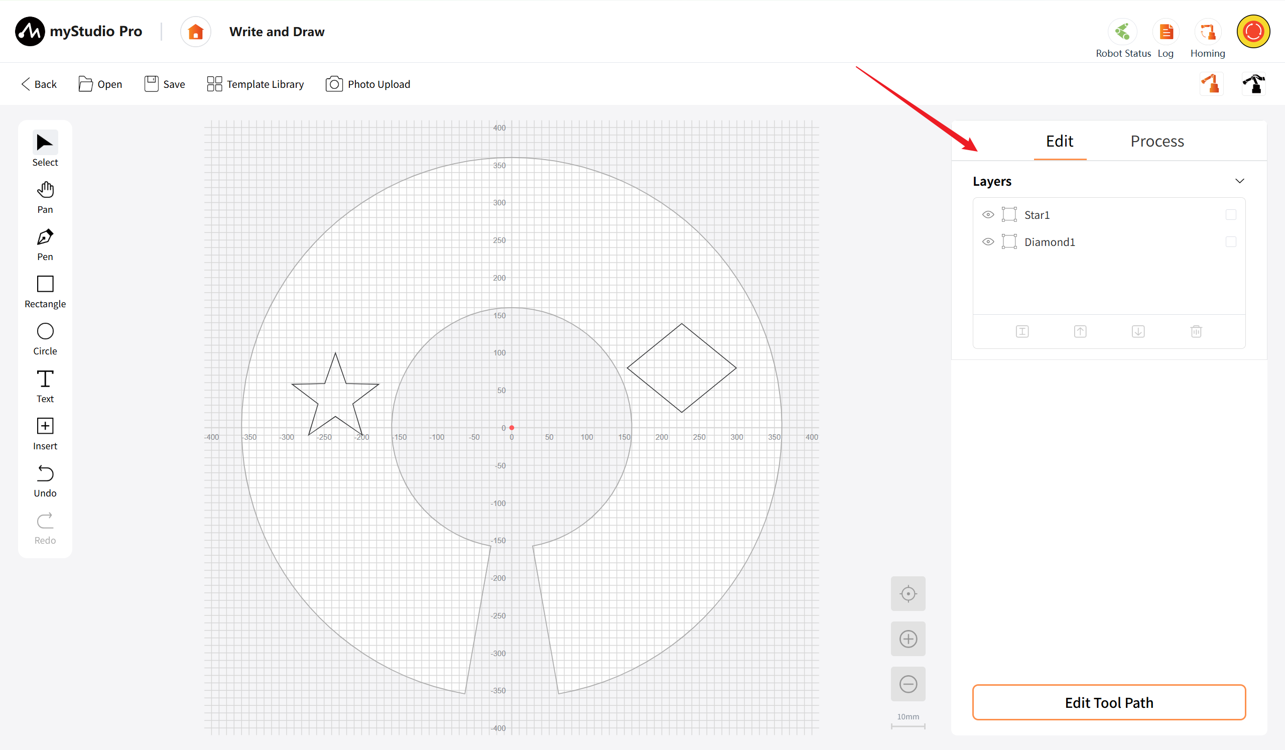
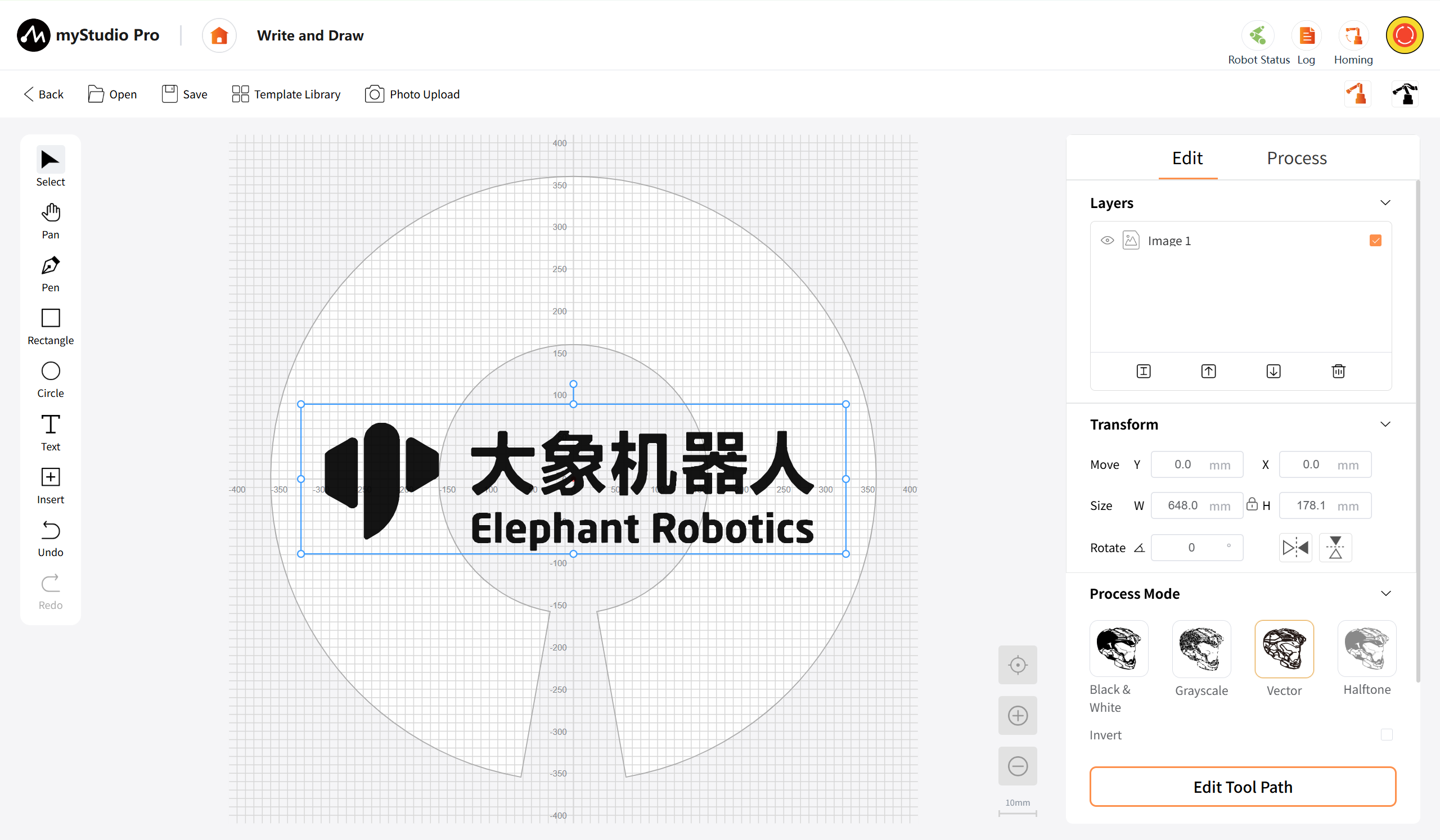
Layers: Displays the list of layers for all graphic objects on the current canvas. Each layer item shows the name of the object. Supports single or multiple selection of layers. When a layer is selected, the corresponding object color on the canvas changes to blue, and the attribute parameters of the object are simultaneously displayed in the corresponding area below (only in the case of single selection). There is a "Show/Hide" button on the left side of each list item, allowing for the display or hiding of the layer.
- When no layer is selected, all four management buttons in the layer list are disabled.
- When a layer is selected (image type), all four buttons are enabled, showing the transformation area and processing mode, and supporting modification of object properties (coordinates, size, whether to rotate or mirror, and image processing mode).
- When a layer is selected (graphic type), all four buttons are enabled, showing the transformation area, and supporting modification of object properties (coordinates, size, whether to rotate or mirror).
- When a layer is selected (text type), all four buttons are enabled, showing the transformation area and text processing, and supporting modification of object properties (coordinates, size, whether to rotate or mirror, and text processing).
- When two or more layers are selected, only the "Delete" button is enabled, while the other three buttons are disabled.
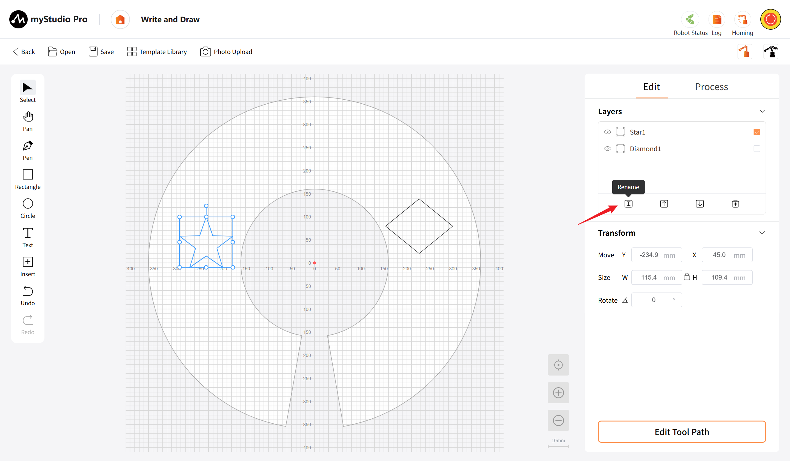
Rename: After selecting the layer, click the button to rename the layer name.
Up: After selecting the layer, click this button, and the current layer will be moved down one position in the list, thus being covered by the layer above. It is also possible to continuously click to move down multiple times until reaching the bottom layer.
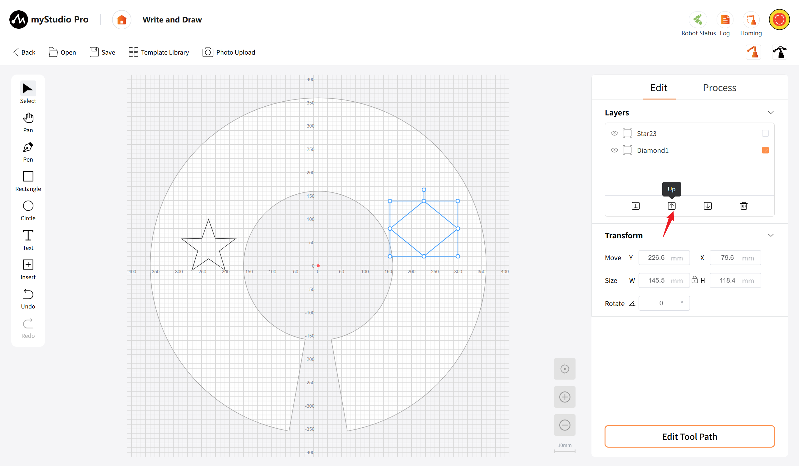
Down: After selecting the layer, click this button, and the current layer will be moved down one position in the list, thus being covered by the layer above. It is also possible to continuously click to move down multiple times until reaching the bottom layer.
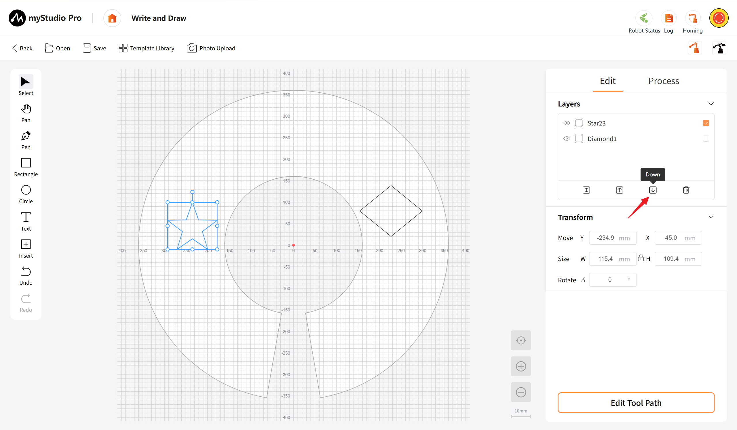
Delete: After selecting the layer, click this button to delete the currently selected layer and the corresponding graphic objects.
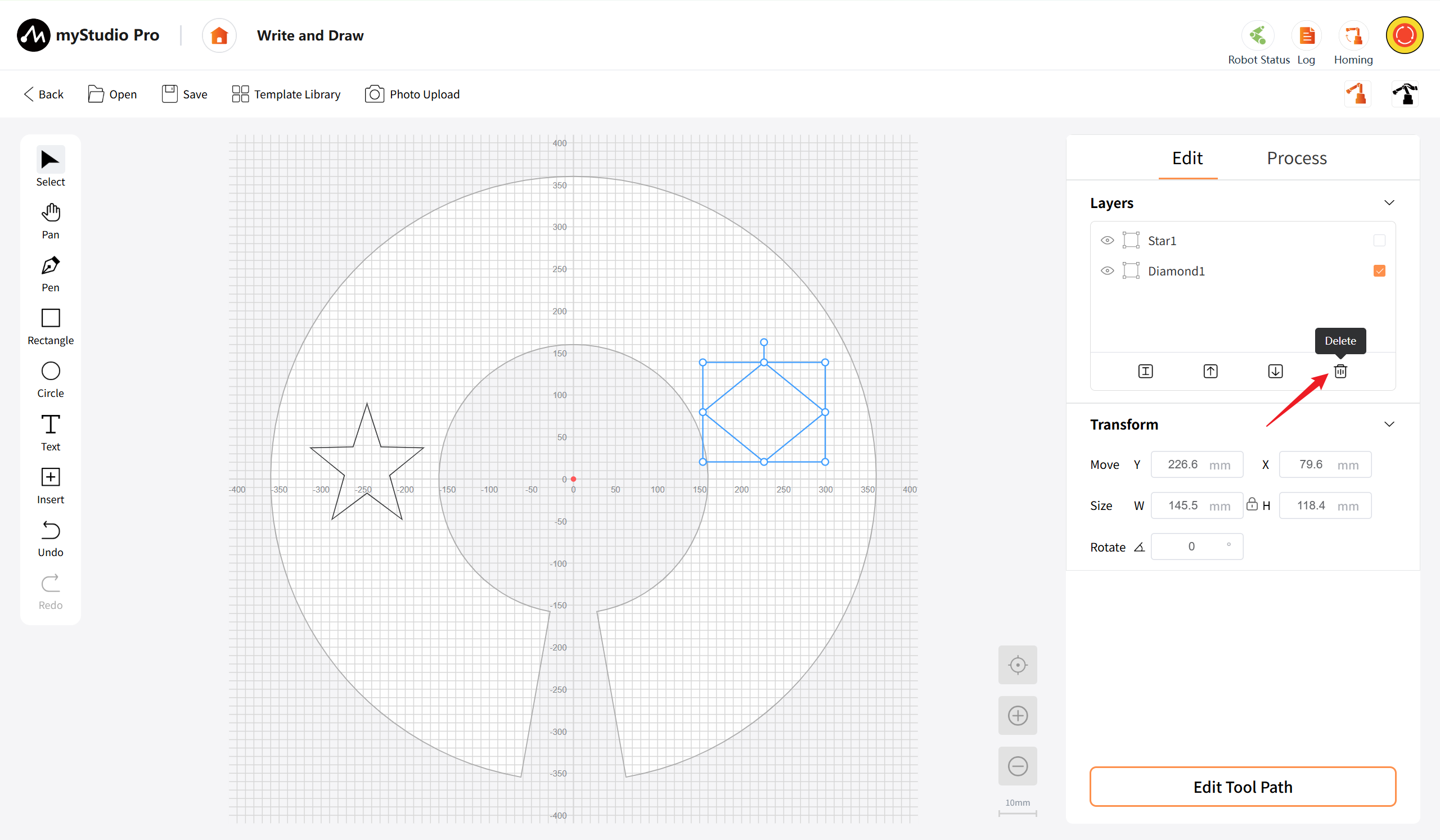
Transformation Area: This area is dedicated to displaying the transformation attribute parameters of the currently selected graphic object. It enables precise adjustment of the object's position, size, and rotation angle by inputting values. This area will only be displayed when a single-layer object is selected.
- Move: Displays the X and Y coordinates (in mm) of the currently selected graphic object. You can directly input numerical values to precisely adjust the position of the object on the canvas. The coordinate origin is the center of the canvas (0.0). Positive and negative values are supported, and the input range is -400 to 400.
- Size: Displays the width (W) and height (H) (in mm) of the currently selected graphic object. You can directly input numerical values to precisely adjust the size of the object. The aspect ratio locking function is supported (controlled by an external button). When either value is modified, the other value changes proportionally.
- Rotate: Displays the rotation angle (in degrees) of the currently selected graphic object. You can directly input numerical values to rotate the object. The input range is 0 to 360. It also supports dragging rotation through the rotation control points on the canvas. The numerical value is updated in real time.
- Horizontal Mirror: After clicking, the currently selected graphic object will be horizontally flipped (left-right mirror) along the vertical axis. The flip center is the geometric center of the object. The center point coordinates of the object remain unchanged, and the graphic content is swapped horizontally. Multiple consecutive mirror flips are supported (each click flips once). This operation supports undo (Ctrl+Z) to restore to the state before the mirror operation.
- Vertical Mirror: After clicking, the currently selected graphic object will be vertically flipped (up-down mirror) along the horizontal axis. The flip center is the geometric center of the object. The center point coordinates of the object remain unchanged, and the graphic content is swapped vertically. Multiple consecutive mirror flips are supported. This operation supports undo (Ctrl+Z) to restore.
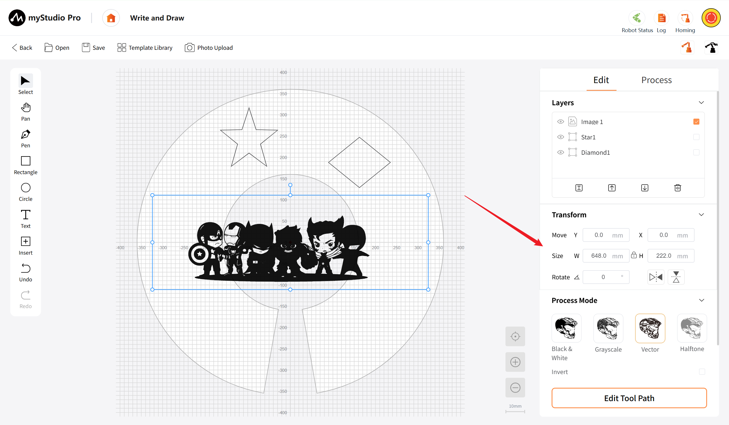
Processe Mode: The processing mode area will only be displayed when only the image object is selected. Four different image processing modes are supported, and the specific display fields will vary depending on the selected mode.
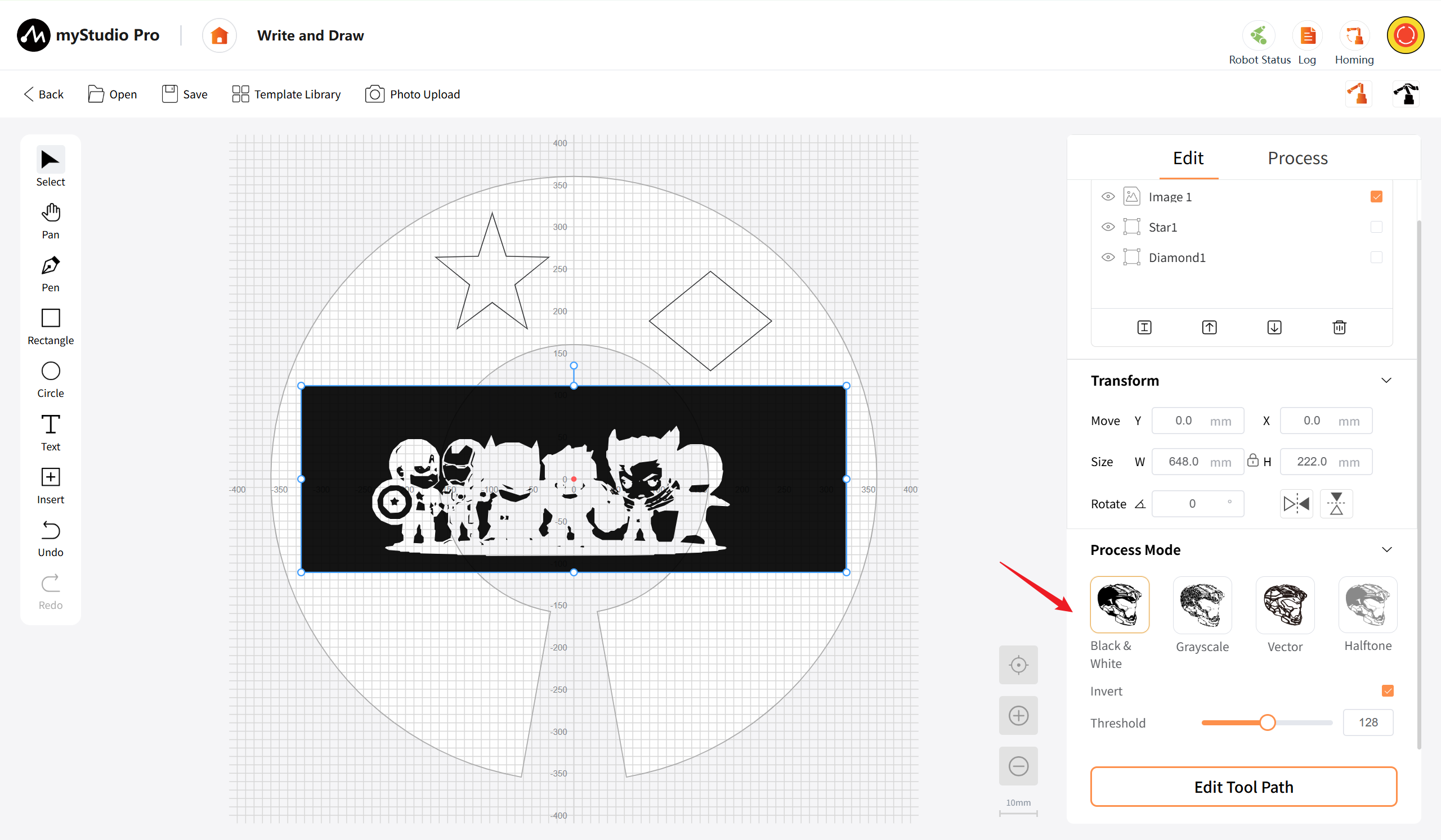
- Black and White: Available when the image object is selected. After clicking, the image will be converted to a black-and-white binary image mode (only retaining black and white colors), which is suitable for generating processed trajectories with clear contrast and distinct outlines.
- Invert: Switch button to reverse the black and white colors.
- Threshold: Supports input box or slider input to set the grayscale threshold (0-255). Pixels above the threshold will be white, and those below the threshold will be black.
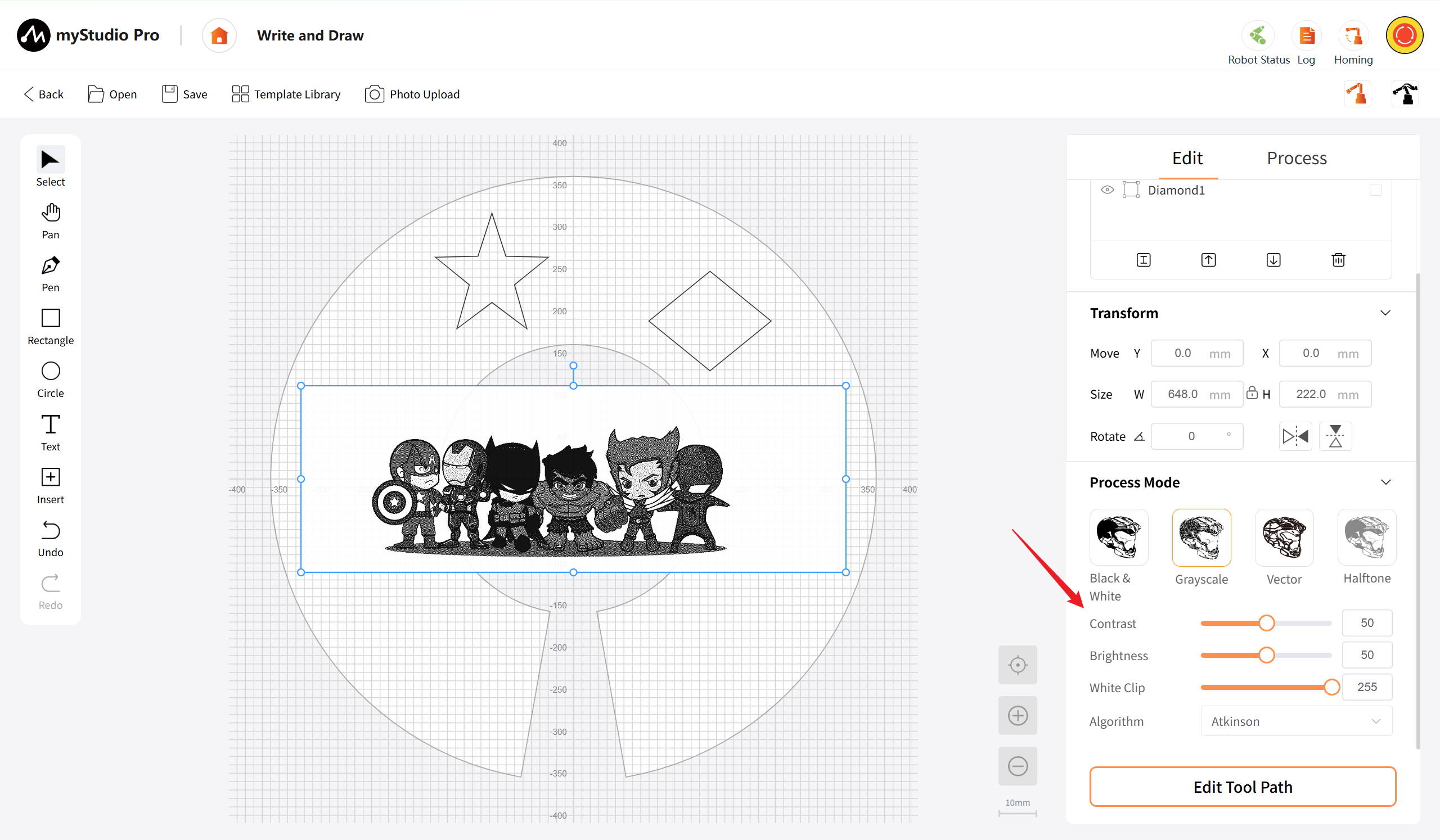
Grayscale: Converts the image into a grayscale one, suitable for creating detailed shading effects.
- Contrast: Supports input through an input box or slider to adjust the contrast between the light and dark areas of the image. The higher the value, the stronger the contrast. The input range is from 0 to 100.
- Brightness: Supports input through an input box or slider to adjust the overall brightness of the image. The input range is from 0 to 100.
- White Clip: Supports input through an input box or slider to set the cut-off value for highlights. Pixels above this value are uniformly processed as white to avoid overexposure and affect the visual effect of the image. The input range is from 0 to 255.
- Algorithm: Clicking the dropdown box allows you to select the image processing algorithm (such as Atkinson, Floyd-Steinberg, etc.), which optimizes the visual effect of grayscale conversion.
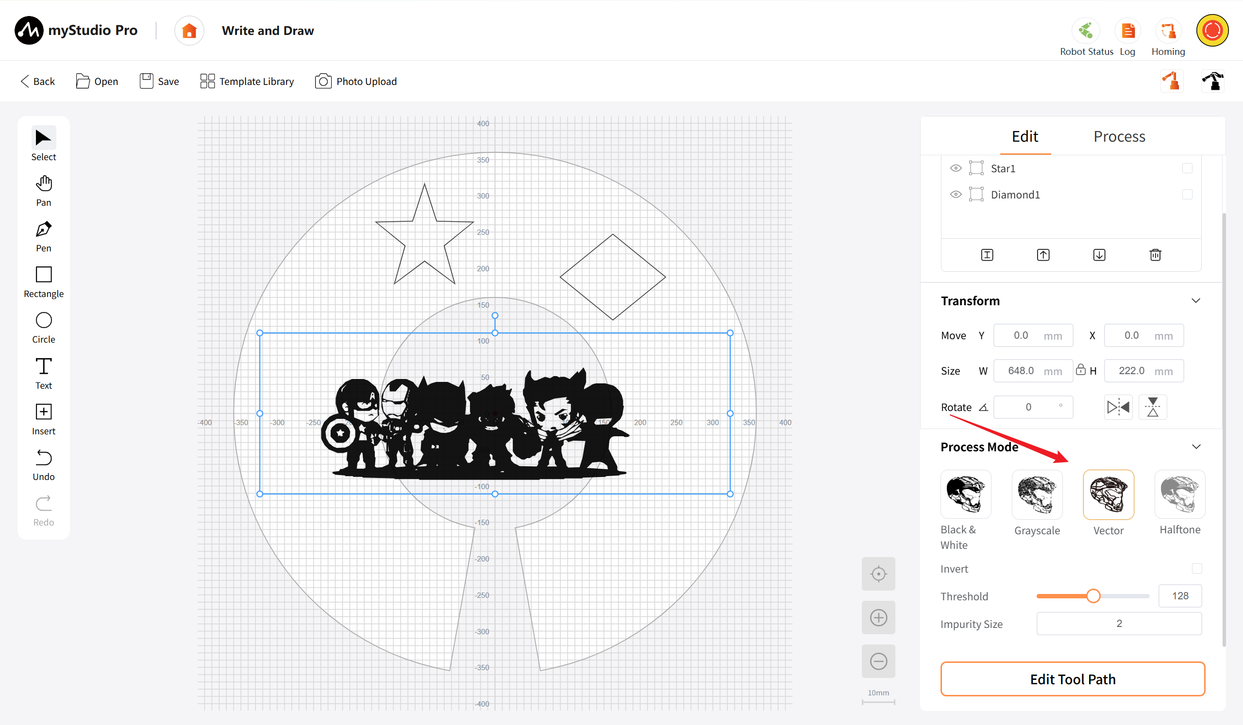
Vector: Converts the image into vector contour paths, generating editable line drawings through edge extraction, making it convenient for subsequent adjustments and optimizations.
- Invert: Switch button to reverse the black and white colors.
- Threshold: Supports input box or slider input to set the grayscale threshold (0-255). Pixels above the threshold will be white, and those below the threshold will be black.
- Impurity size: Supports input box or slider input to set the minimum allowed impurity size to be displayed. Filters out isolated noise points smaller than this value in the image, making the generated trajectory cleaner. The input range is 0 to 1000.
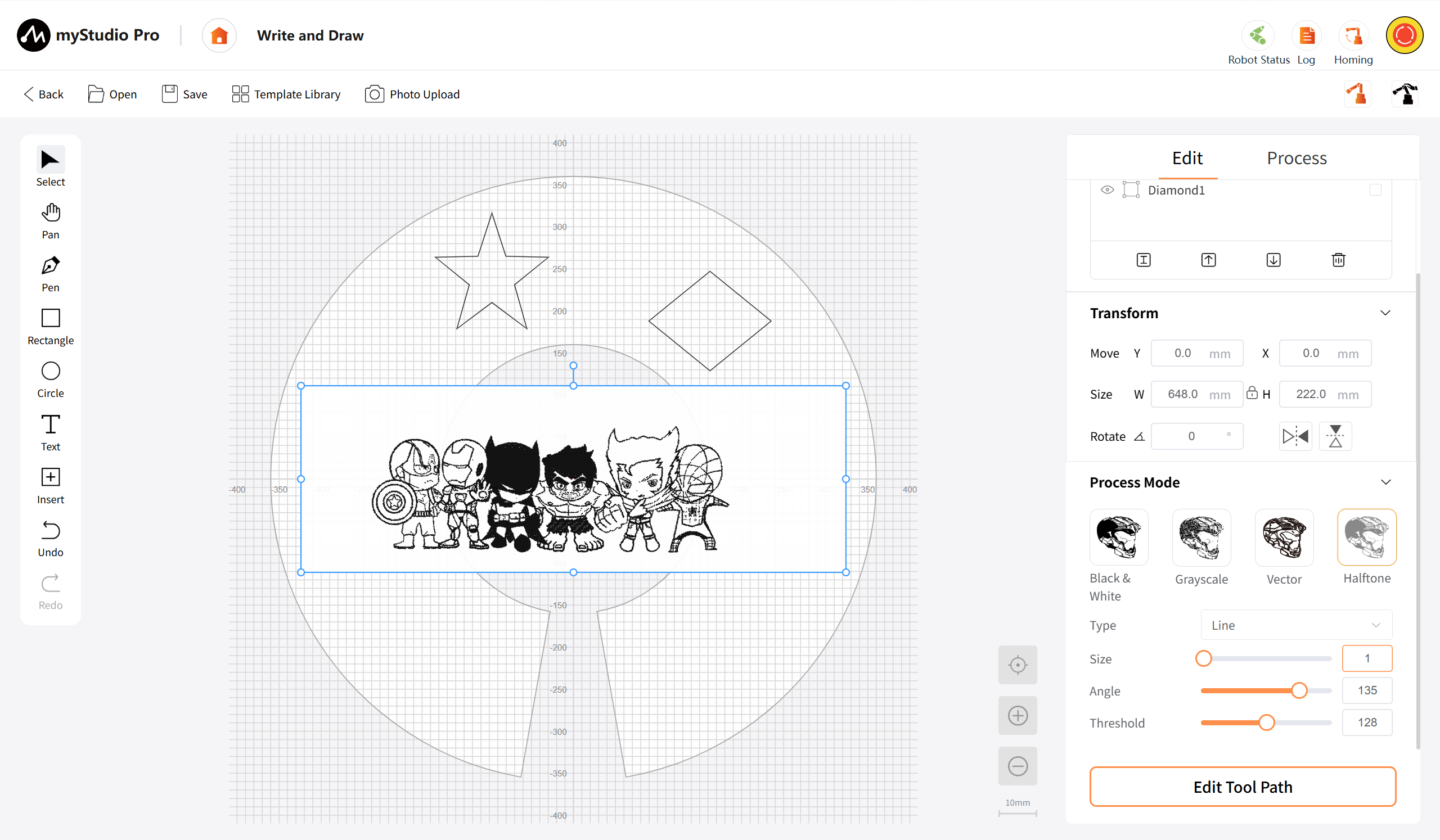
Halftone: Converts the image into a halftone dot matrix or line effect, using different sizes or densities of dots/lines to simulate the light and dark areas of the image. This is suitable for artistic processing effects.
- Type: Arrangement method of selected points.
- Size: Supports input box or slider input to set the size of the points. The input range is from 0 to 50.
- Angle: Supports input box or slider input to set the rotation angle of the selected object. The input range is from 0 to 180.
- Threshold: Supports input box or slider input to set the gray level threshold (0-255). Pixels above the threshold will be white, and pixels below the threshold of 0 will be black.
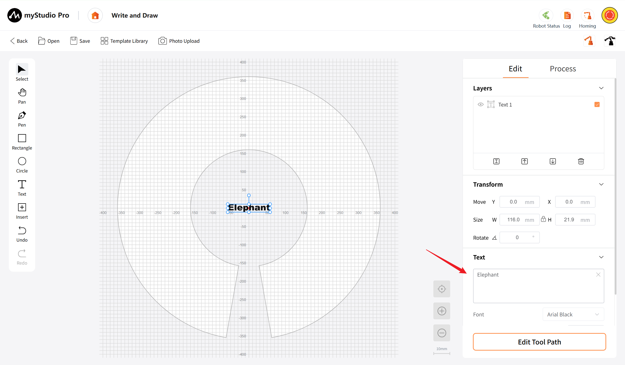
Text: When a text object is selected on the canvas, the area displays the settings related to the text attributes, allowing for adjustments to the text style.
- Font: A dropdown selection box. Clicking on it will expand the list of installed fonts, allowing you to select a font to apply to the currently selected text object. After selection, the selected text will immediately update to the corresponding font style. The default font used for the current text is displayed (e.g., "Arial Black-Regular")
- Font size: A numeric input box for setting the font size of the text, with units in pt (points). The size of the selected text is updated in real time after modification.
- Alignment: Three buttons are provided to control the horizontal alignment of the text object within its bounding box: left alignment, center alignment, and right alignment. The button corresponding to the currently selected alignment is highlighted. After changing the alignment, the position of the selected text is adjusted in real time.
Tool Path List
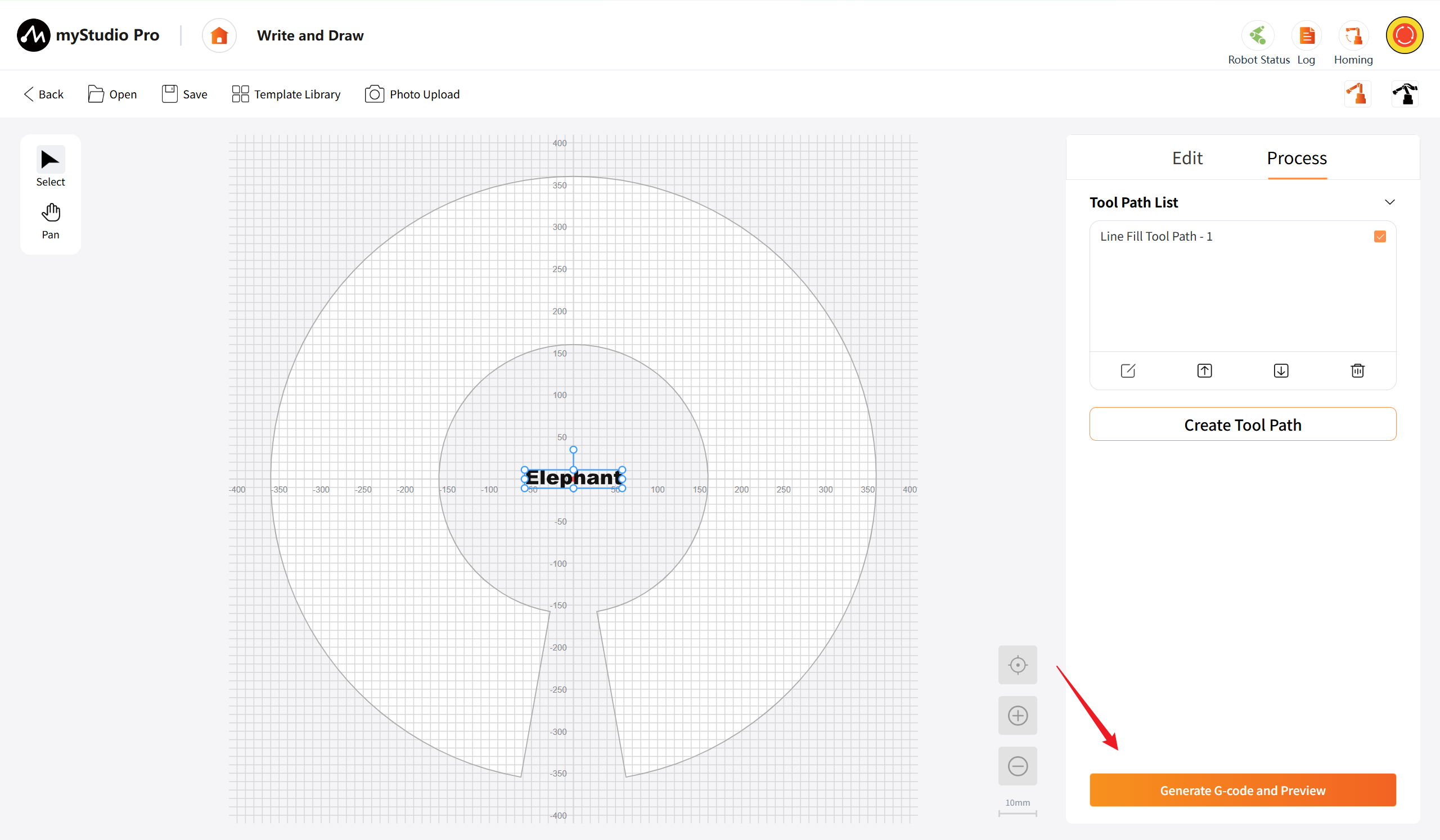
Display all the created tool path entries in the current project, arranged from top to bottom in the order of processing.
Edit: After selecting the tool path, click this button to expand the detailed parameter setting area for this path, making it easier to modify various processing parameters. This function is the same as double-clicking the path entry.
Up: After selecting the tool path, click this button. The current path in the list will be moved one position upwards, meaning the processing priority will be advanced. You can also click this button multiple times in succession to move it to the top.
Down: After selecting the tool path, click this button. This will move the current path one position down in the list, which means the processing priority will be shifted to the next level. It is also supported to click this button multiple times in succession to move it all the way to the bottom.
Delete: After selecting the tool path, click this button. A secondary confirmation dialog box will pop up, stating "Delete this tool path? This action cannot be undone.." After confirming, the current selected tool path and all its parameter configurations will be deleted, and the list will automatically refresh.
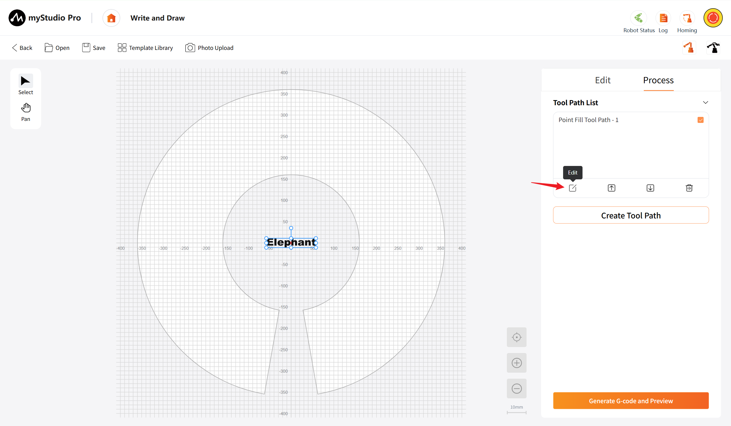
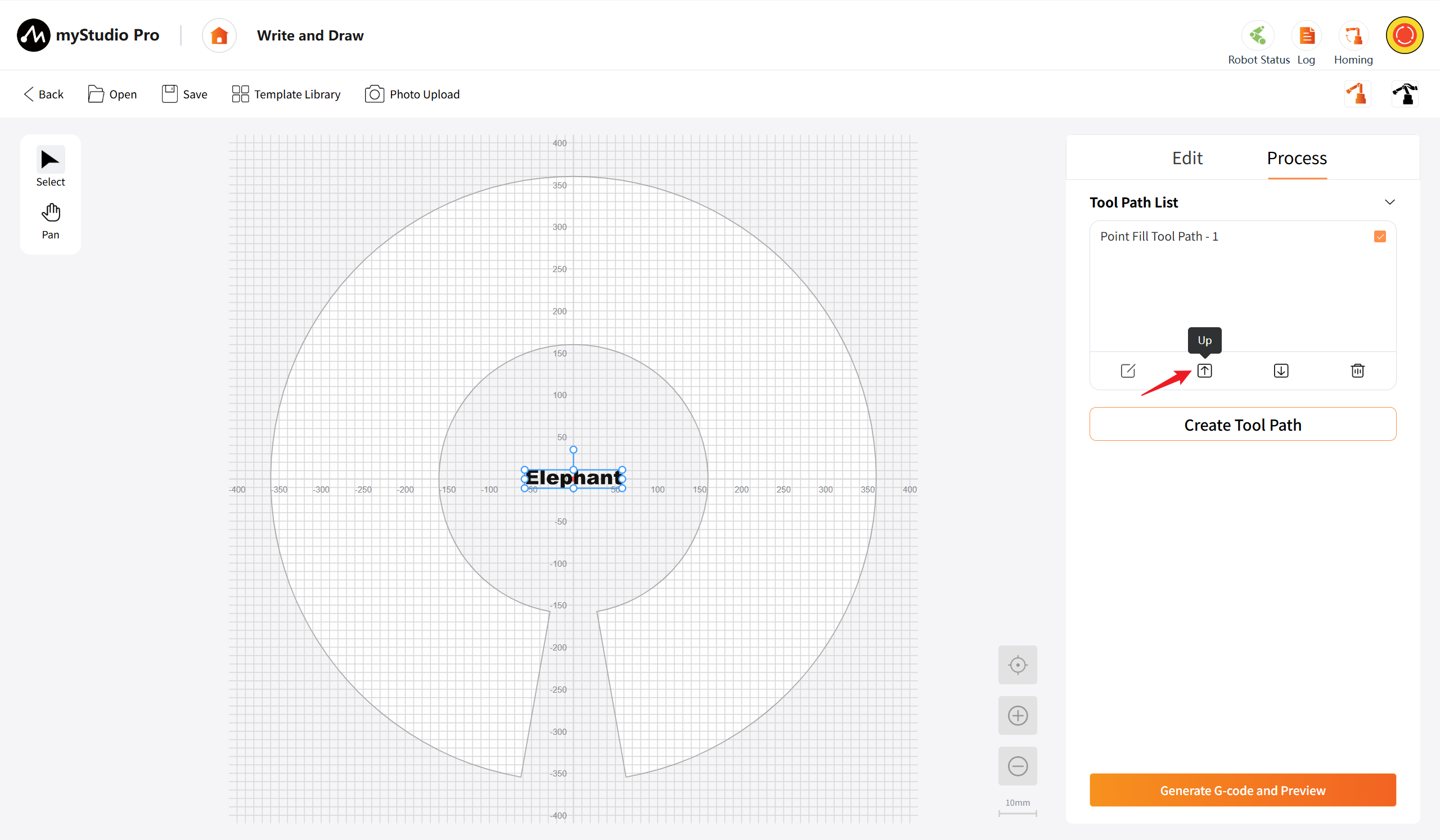
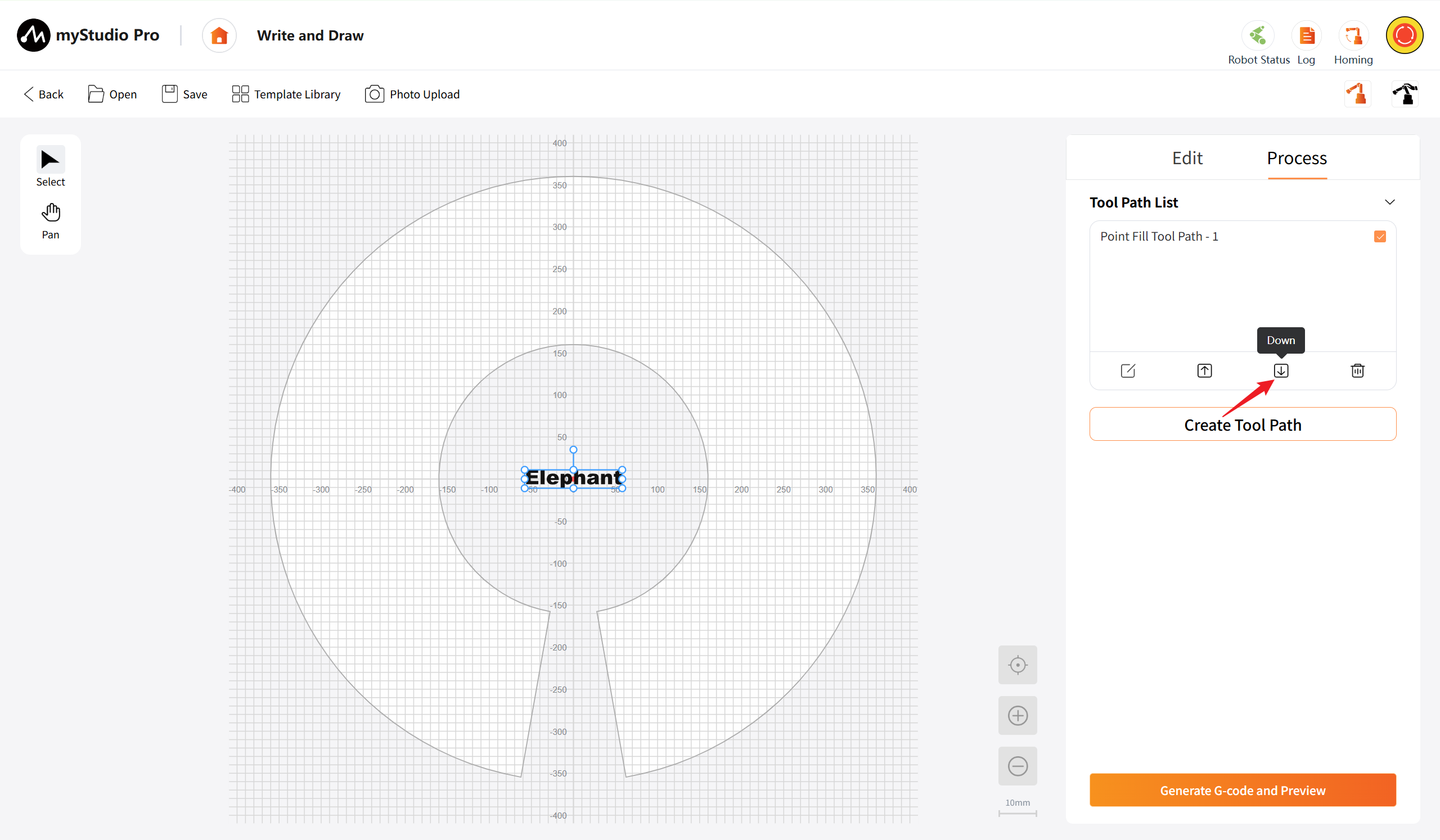
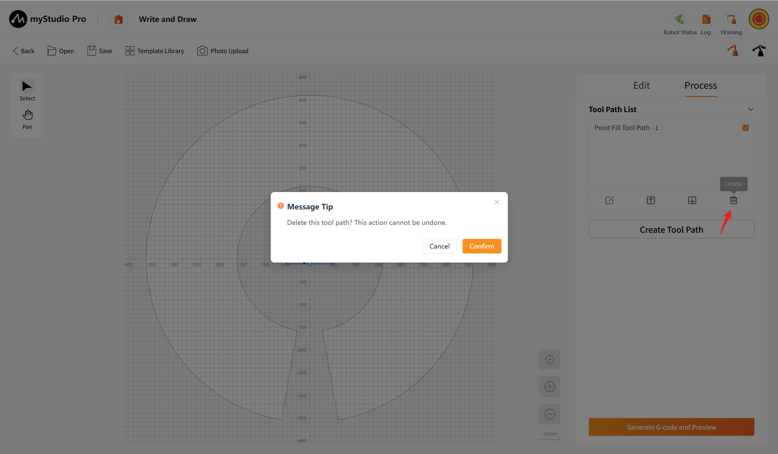
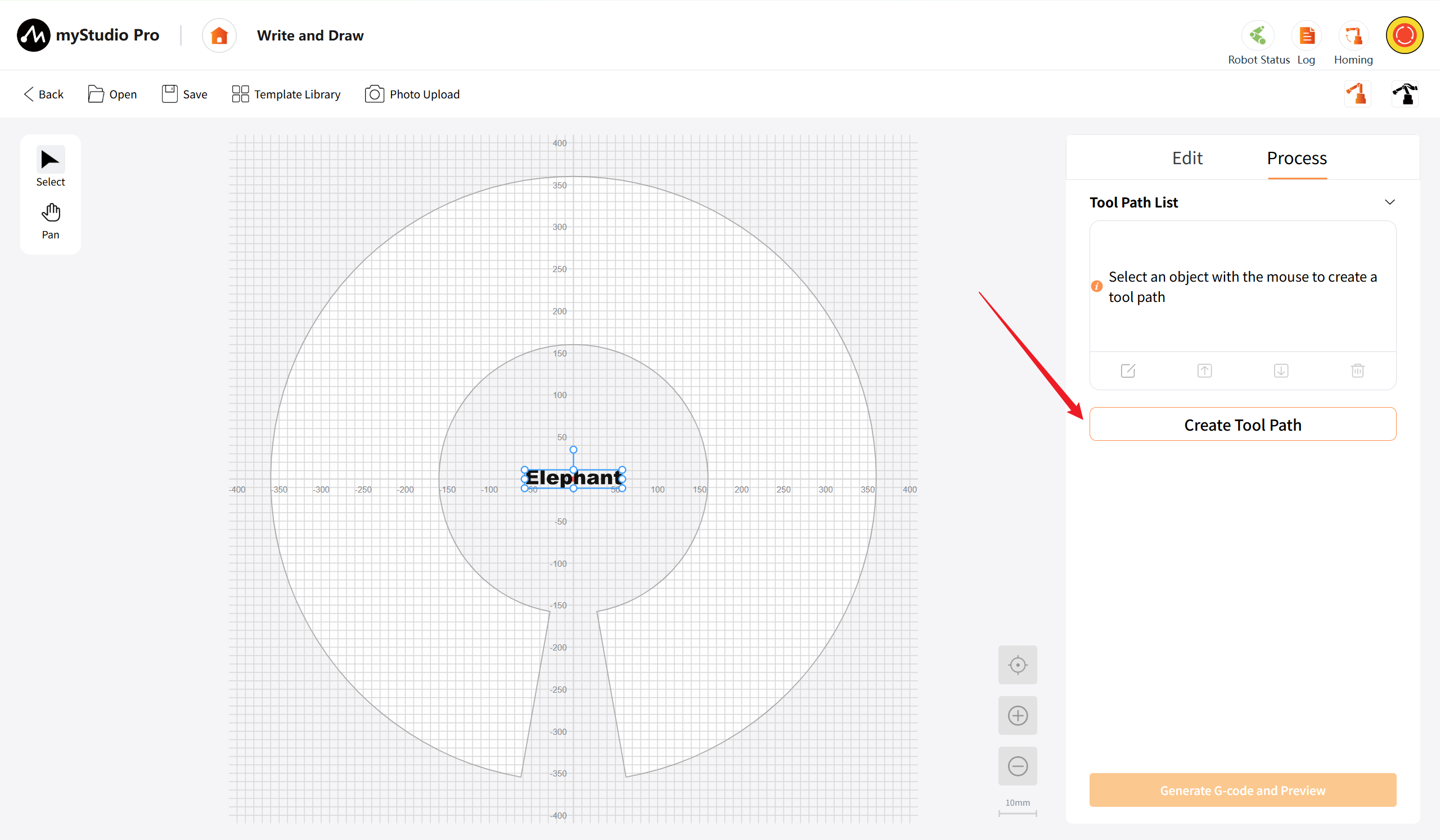
Create Tool Path: Select one or more graphic objects on the canvas. This button becomes enabled, while the others remain disabled. After clicking, a tool path is created based on the selected graphic objects, and the "Tool Path Parameter Settings" will be displayed.
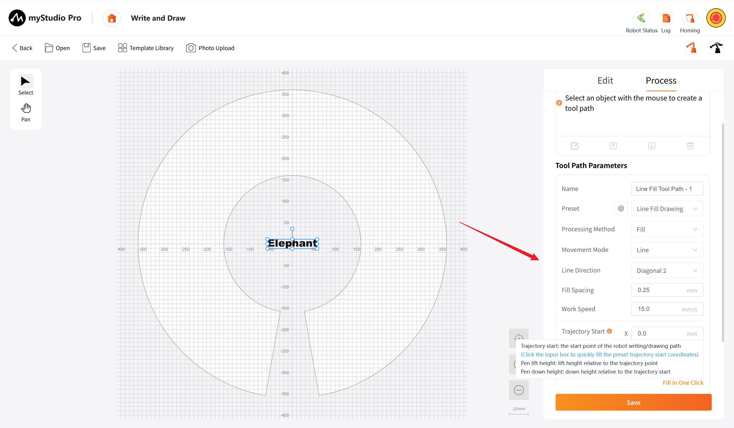
Tool Path Parameters: This area is used to create and edit the detailed parameters of a single tool path, including path name, preset mode selection (point/line/vector engraving), processing parameters, movement method in fill mode, line direction, fill spacing, etc. After completing the parameter settings, save them. The path will then be added to the tool path list, ready for subsequent processing sorting and execution.
- Name: Customizable identifier name for the current tool path to facilitate identification and management in the list.
- Preset: Dropdown selection for preset processing templates (such as point filling drawing, line filling drawing, vector drawing). After selection, the corresponding parameters will be automatically filled in, and modifications can be made on this basis.
- Processing Method: Click the dropdown box to select the path generation method. If the preset configuration selection is "point filling drawing" and "line filling drawing", the automatic filling parameters are "filling"; if the preset configuration selection is "vector drawing", the automatic filling parameters are "along the path". Customization is supported.
- Movement mode: (Shown when the processing method is "filling") Click the dropdown box to select the filling movement mode: line, point. If the preset configuration selection is "point filling drawing", the automatic filling parameters are "point"; if the preset configuration selection is "line filling drawing", the automatic filling parameters are "line". Customization is supported.
- Line Direction: (Shown when the movement mode is "lines") Click the dropdown box to set the direction of the filled lines: horizontal, vertical, diagonal 1, diagonal 2. Diagonal 1 direction refers to from left to right. Diagonal 2 direction refers to from right to left.
- Fill spacing: (Shown when the processing method is "filling") Click the input box to fill in the filling spacing. The range is 0.05 to 6000. The unit is mm. When the movement mode is selected as "lines", the system automatically fills in the parameters as 0.25mm; when the movement mode is selected as "points", the system automatically fills in the parameters as 0.14mm. Customization is supported.
- Work speed: Click the input box to input the moving speed of the robotic arm during processing. The value range is 0.1 to 100. The unit is mm/s. The default is 15mm/s.
- Pen Up height: Set the height of the tool lifting during the processing (unit mm). The range is 0 to 999999. The default is 5mm.
- Pen down height: Set the height of the tool contacting the material during the processing (unit mm), which determines the processing depth. The range is 0 to 999999. The default is 5mm.
- Trajectory start: The preset starting point of the processing trajectory, which can be pre-set in the "Quick Movement Page" and supported by one-click filling.
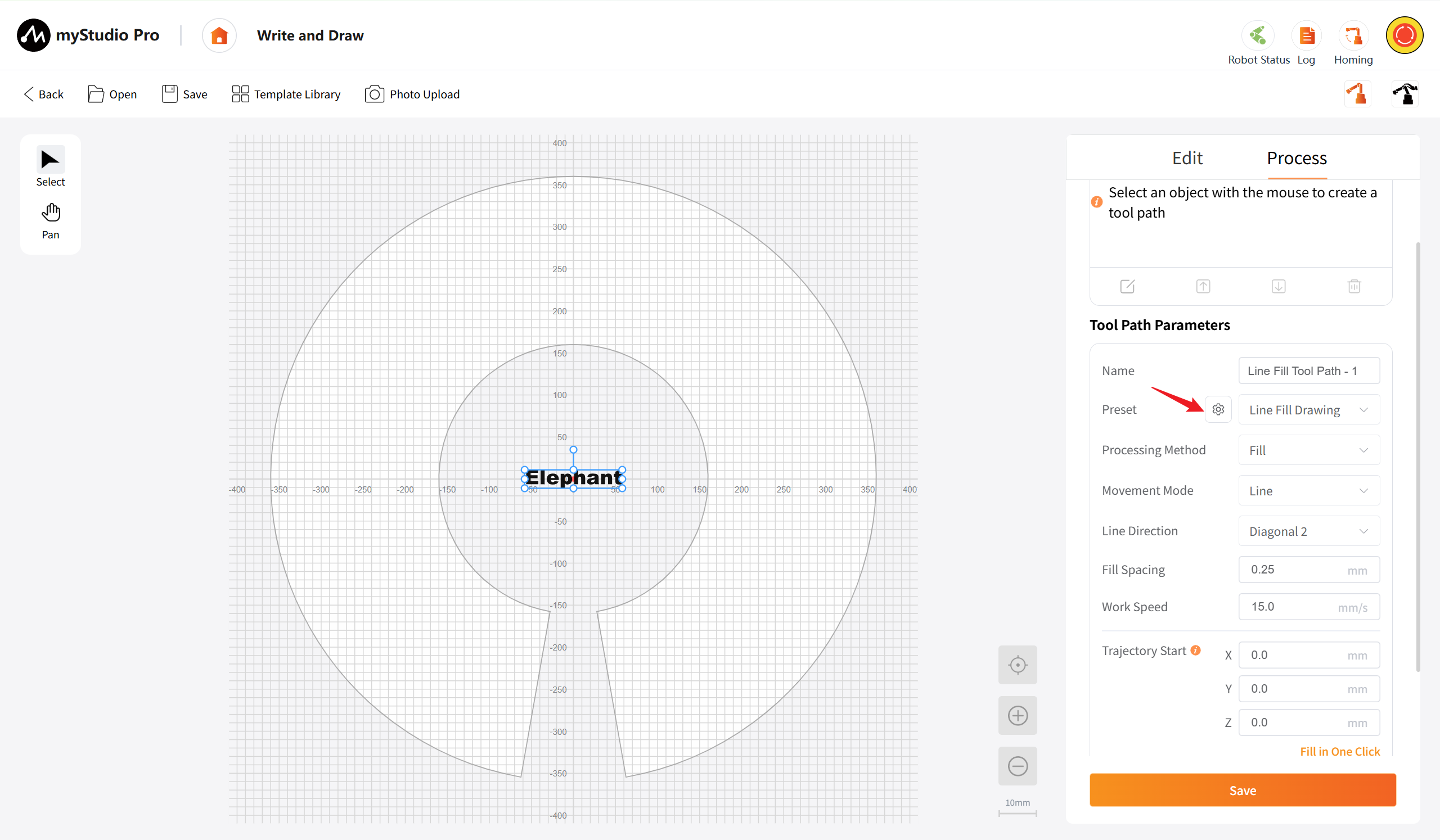
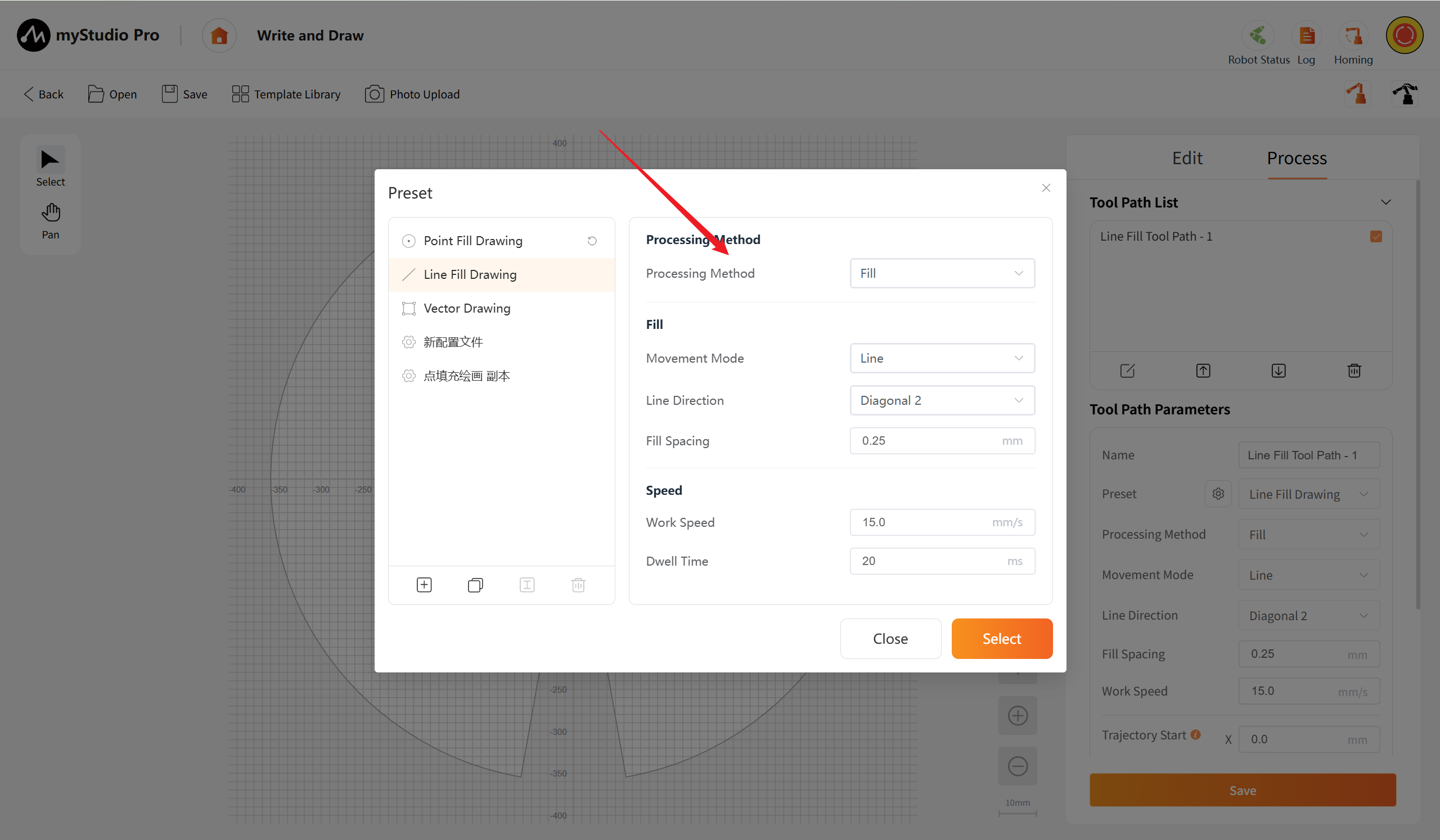
Preset: Clicking the button will pop up the "Default Configuration Settings Dialog Box. This button is only available when the tool path is selected.
Generate G-code and preview: When one or more tool paths are selected in the tool path list, this button becomes enabled. Clicking the button will then navigate to the "Preview" page.
Default Configuration List: This area displays all available preset configuration templates, and only single selection is supported.
- System default preset: Point fill painting, Line fill painting, Vector painting (cannot be deleted or renamed, but can be created as copies based on them).
- User-defined preset: Configuration items generated by the user through "Create" or "Copy", with default names such as "New Configuration File", support renaming and deletion.
- Clicking on a list item enables selection of the configuration, and the right parameter configuration area synchronously displays the detailed parameters of the selected configuration.
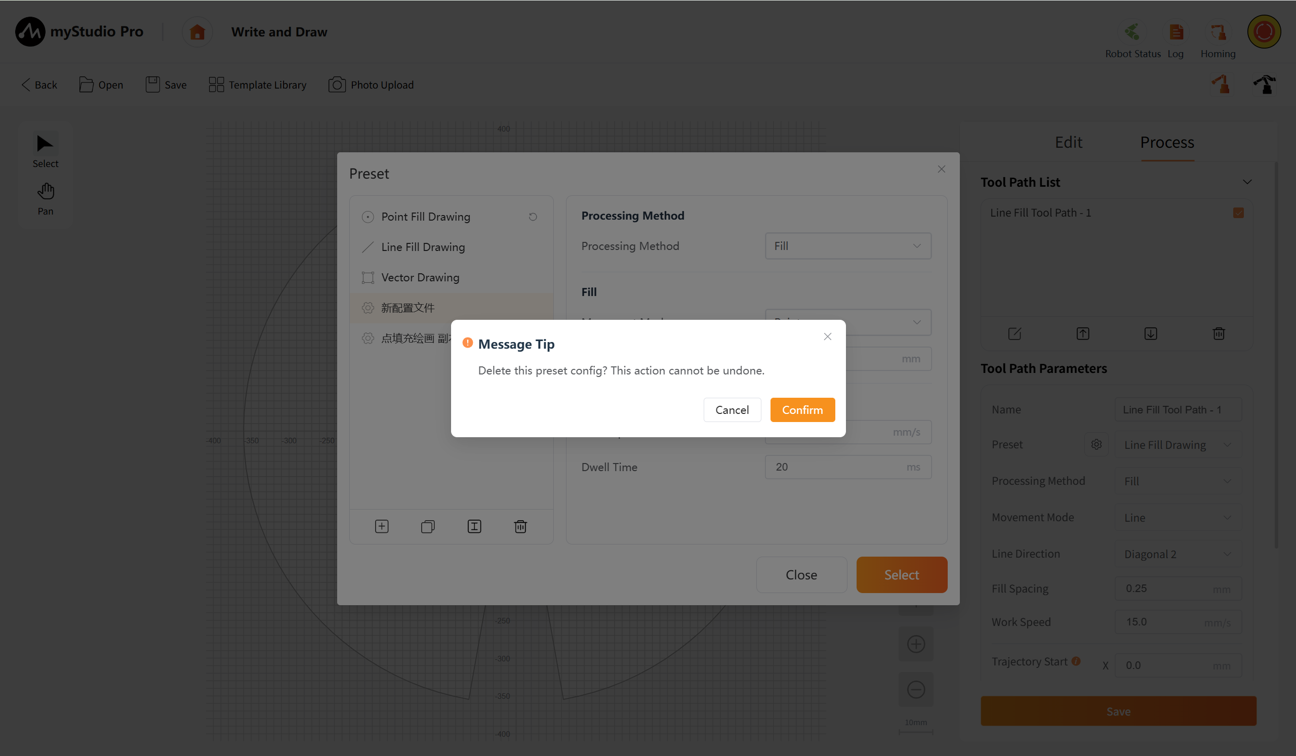
- When the system default configuration is selected, the "Rename" and "Delete" buttons become grayed out and disabled.
- Support for users to modify configuration parameters. If the system default configuration is modified by the user, an "Restore" icon appears, and clicking the "Restore" icon can restore the system configuration. Clicking the "Restore" icon of the list item can restore all parameters. If the "Restore" icon in the right parameter configuration area is clicked, a single click only restores one field. If the custom configuration modified by the user is selected, the "Restore" icon will not appear.
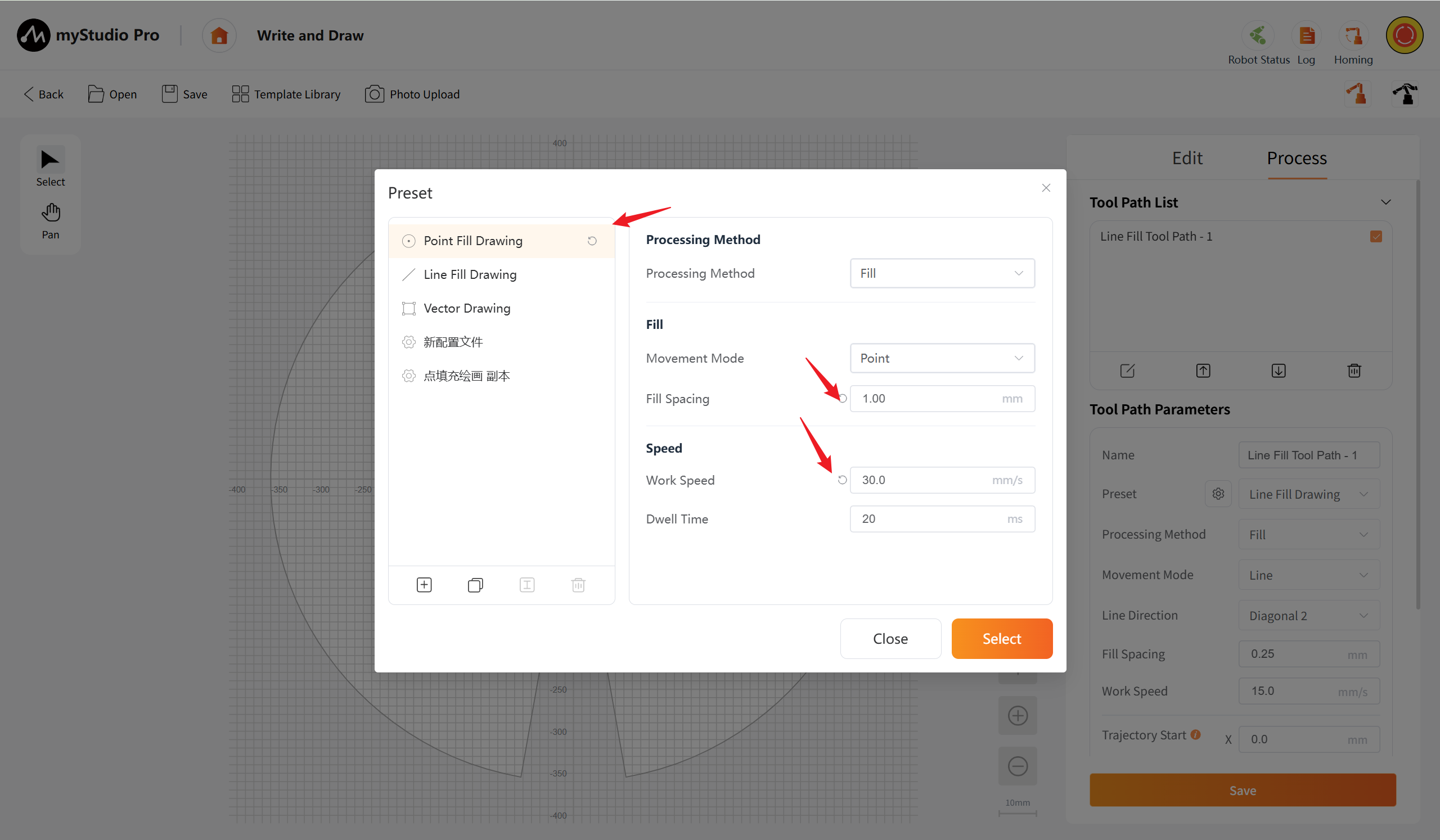
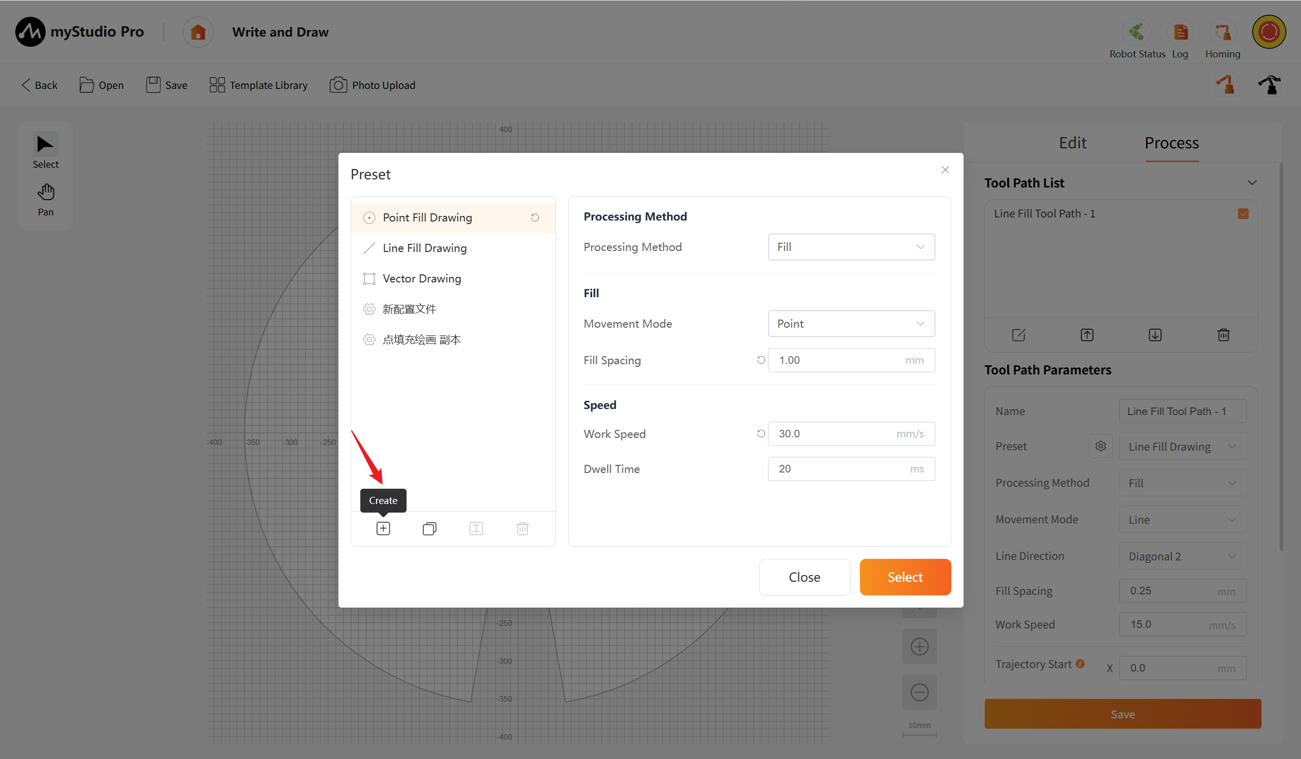
Create: Click the button to open a pop-up window where you can input the name of the new configuration file to create a new preset configuration template. After saving, the new configuration will be added to the end of the list and automatically selected.
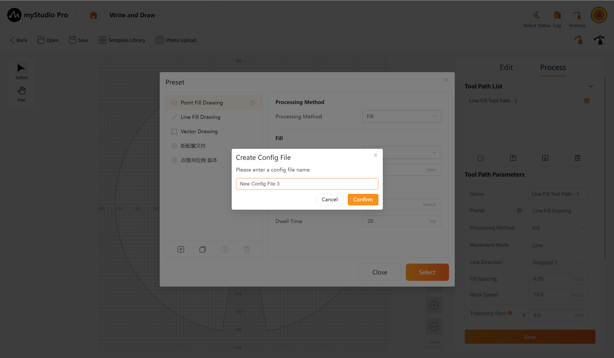
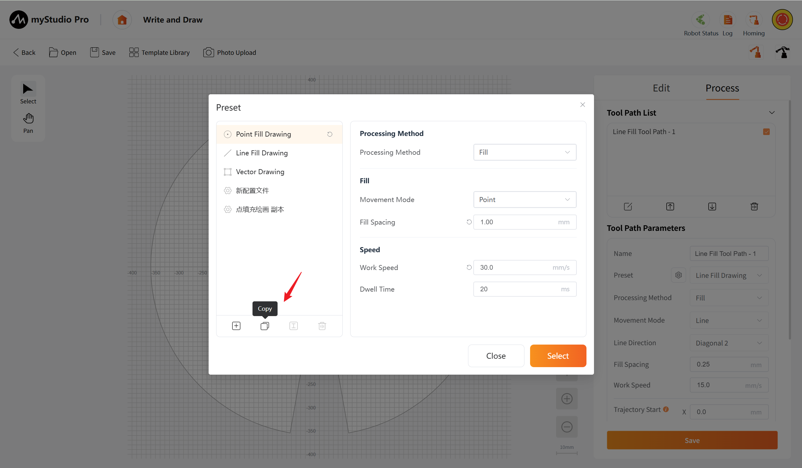
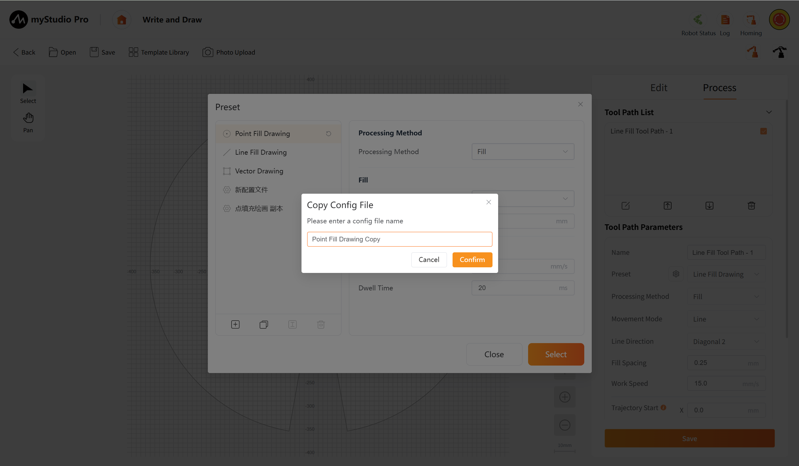
Copy: After clicking the button based on the currently selected preset configuration, a copy will be generated. A "Copy Configuration File Dialog Box" will pop up. Enter the name of the new configuration file, confirm, and a new configuration item will be created and added to the end of the list.
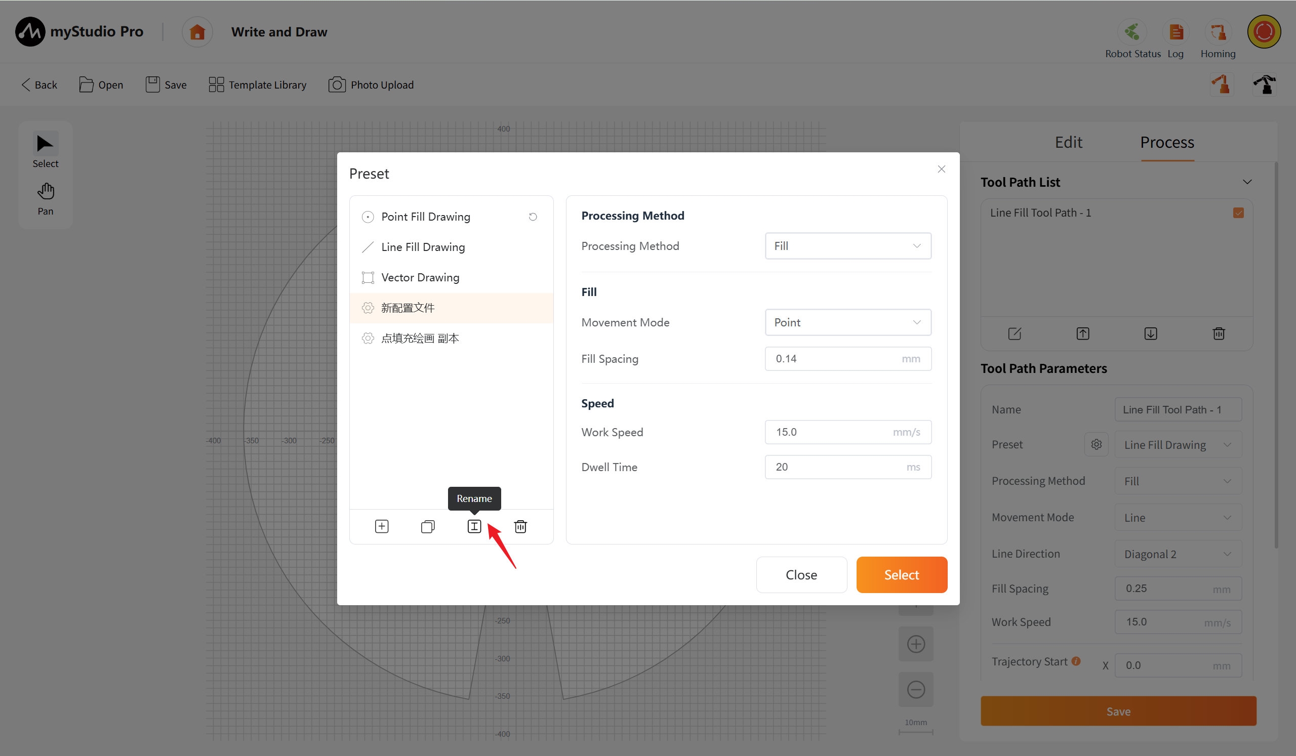
Rename: Change the name of the currently selected custom preset configuration.
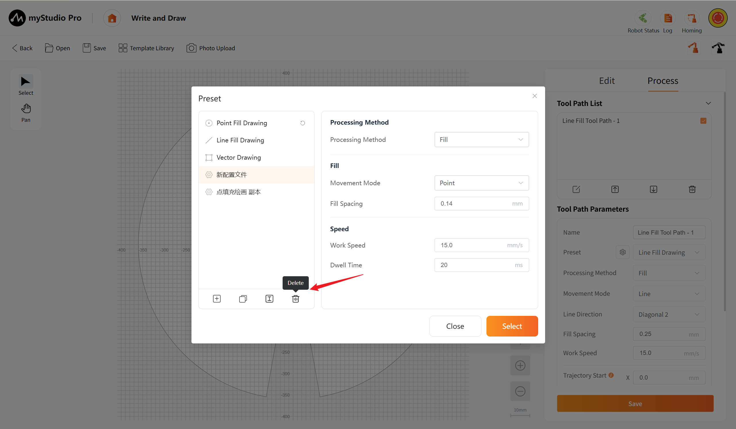
Delete: Delete the currently selected custom preset configuration.
Parameter Configuration Area: Displays and allows editing of the detailed processing parameters for the currently selected preset configuration.
- Process method: Click the drop-down box to select the path generation method: Fill, Along Path.
- Movement mode: (Shown when the processing method is "Fill") Click the drop-down box to select the filling movement method: Line, Point.
- Line direction: (Shown when the movement mode is "Line") Click the drop-down box to set the direction of the filled line: Horizontal, Vertical, Diagonal 1, Diagonal 2. Diagonal 1 direction refers to from left to right. Diagonal 2 direction refers to from right to left.
- Fill spacing: (Shown when the processing method is "Fill") Click the input box to fill the filling spacing. The range is 0.05 to 6000. The unit is mm. When the movement mode is selected as "Line", the system automatically fills the parameters as 0.25mm; when the movement mode is selected as "Point", the system automatically fills the parameters as 0.14mm. Customization is supported.
- Work speed: Click the input box to input the movement speed of the robotic arm during processing. The value range is 0.1 to 100. The unit is mm/s. The default is 15mm/s.
Preview Page
After the user completes graphic creation on the workbench, by clicking the "Generate G-code and Preview" button, they will be directed to the dedicated preview and debugging interface. The page focuses on verifying and preparing for the execution of the current generated G-code file, and does not support graphic editing. This ensures that the user can concentrate on the final confirmation of the processing file.
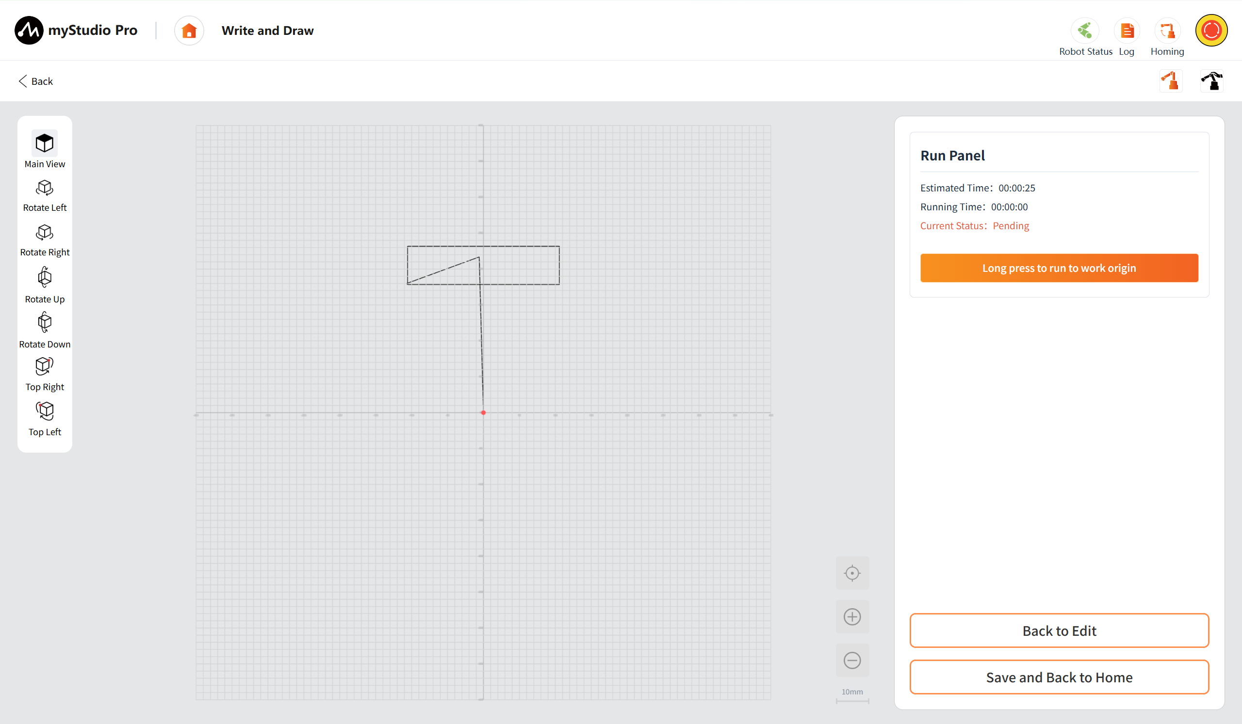
It is mainly divided into the following areas:
Top Toolbar
It offers the functions of returning, rapid movement and free movement, facilitating users to quickly position the robotic arm and calibrate the initial point during the processing.
Back: Clicking "Return" will take you back to the previous page.
Quick Movement: As on the main page, click to open the Quick Movement Page.
Free Movement: Consistent with the main page, click to open the free movement pop-up window.
Left View Control Area
Integrated with multi-directional view adjustment buttons (main view, left rotation/right rotation/upward rotation/downward rotation to adjust the viewing angle, and upper left point/upper right point to quickly position the view center to the upper left or upper right point of the work area), facilitating users to examine the processing trajectory from multiple dimensions.
Main View: After clicking the button, the 3D preview area will be restored to its default initial perspective. The main view of this page is set as a top-down view by default.
Rotate Left: Support single-click and long-press. Click to rotate 15 degrees, and long-press to rotate continuously to the left at a speed of 30 degrees per second until you release the button to stop.
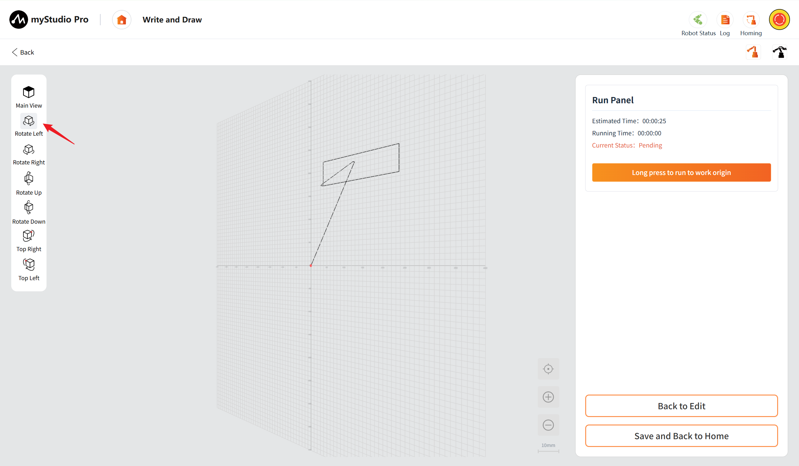
Rotate Right: Support single-click and long-press. Click to rotate 15 degrees, and long-press to rotate continuously to the right at a speed of 30 degrees per second until you release the button to stop.
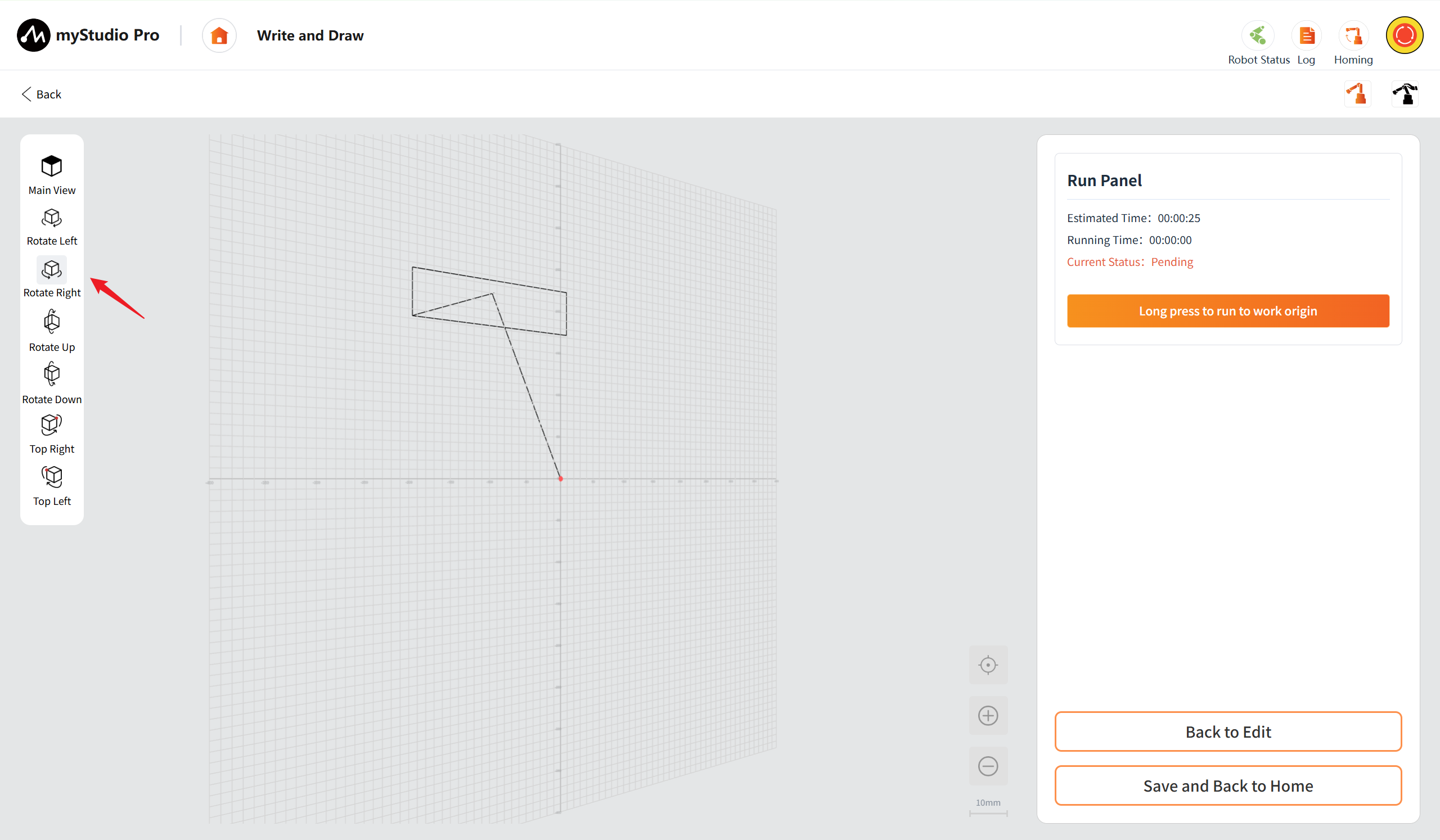
Rotate Up: Support single-click and long-press. Click to rotate 15 degrees, and long-press to rotate upwards at a speed of 30 degrees per second continuously until the button is released to stop.
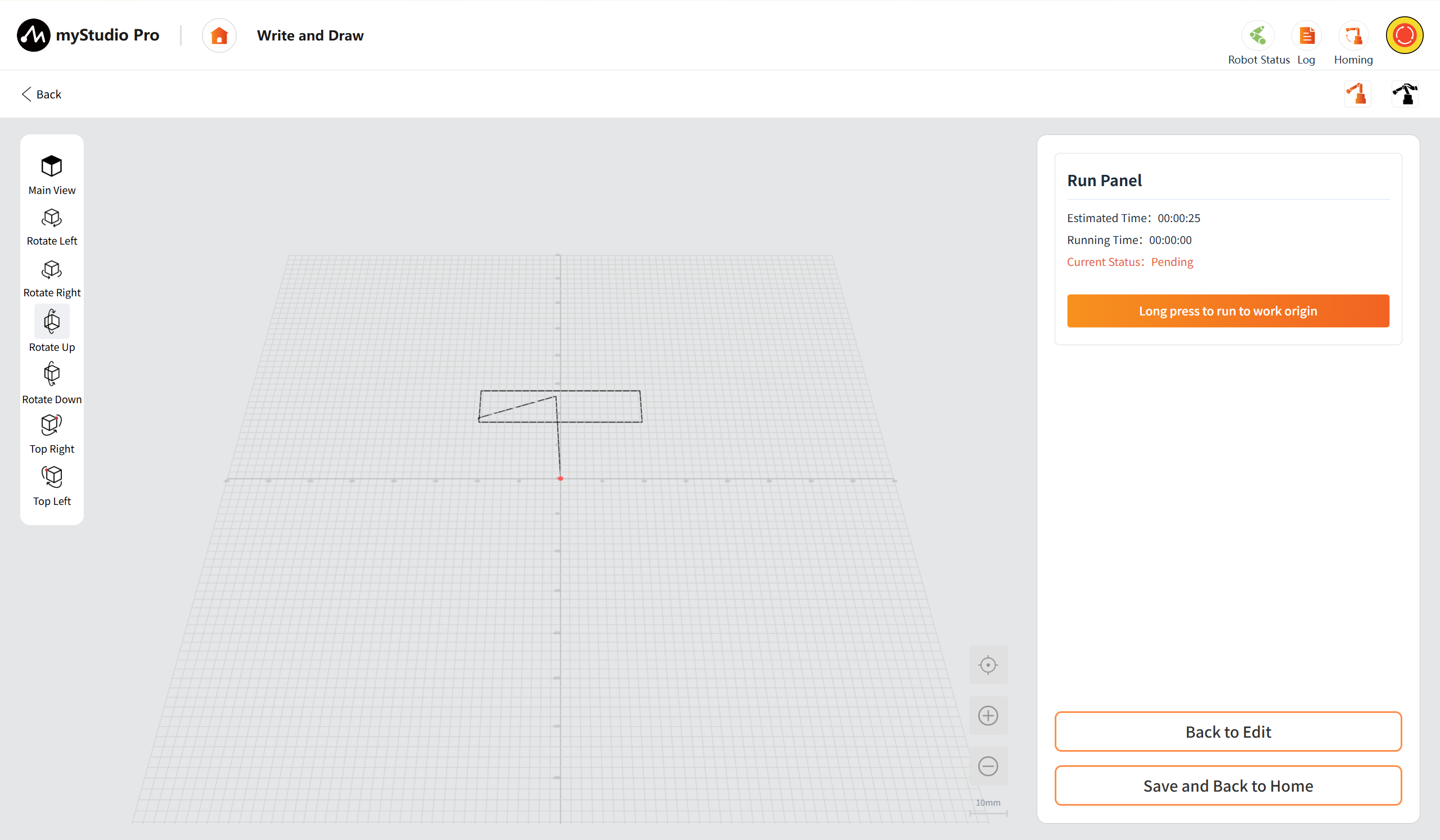
Rotate Down: Support single-click and long-press. Click to rotate 15 degrees, and long-press to rotate downward at a speed of 30 degrees per second continuously until you release the button to stop.
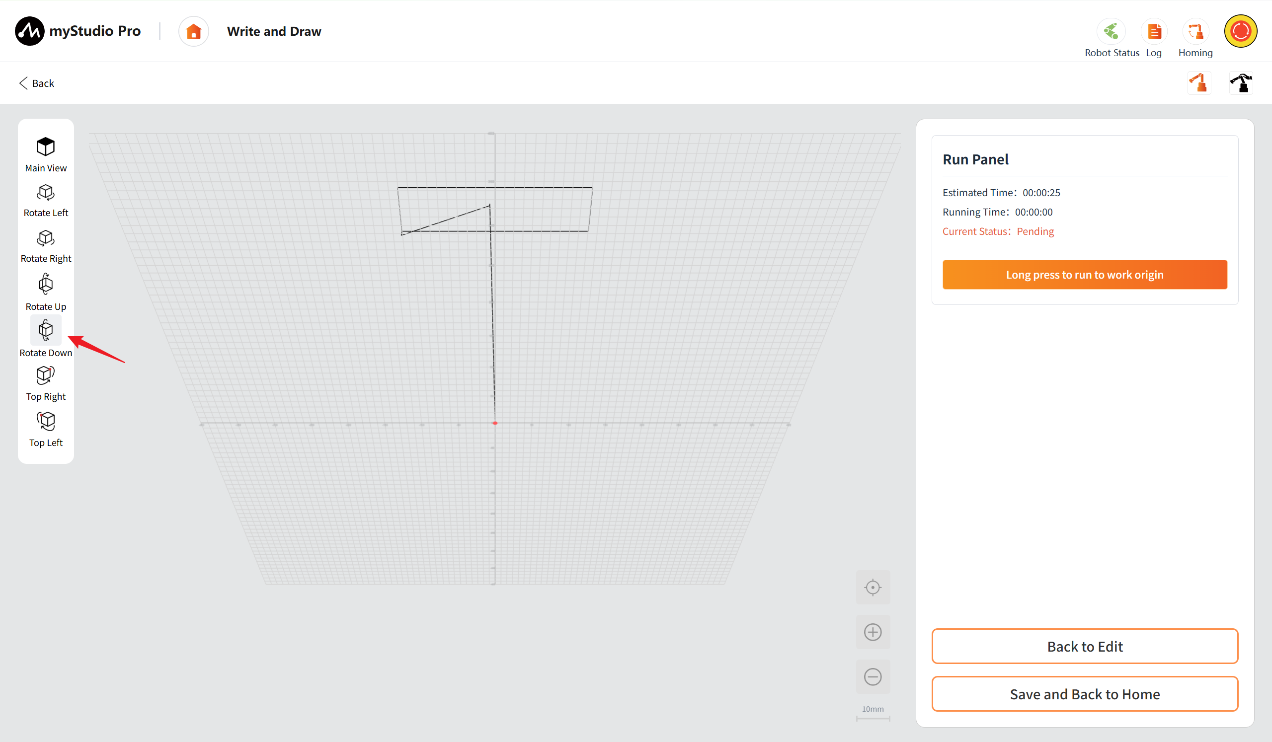
Top Right: After clicking the button, the viewing center will be quickly positioned to the upper right point of the work area.
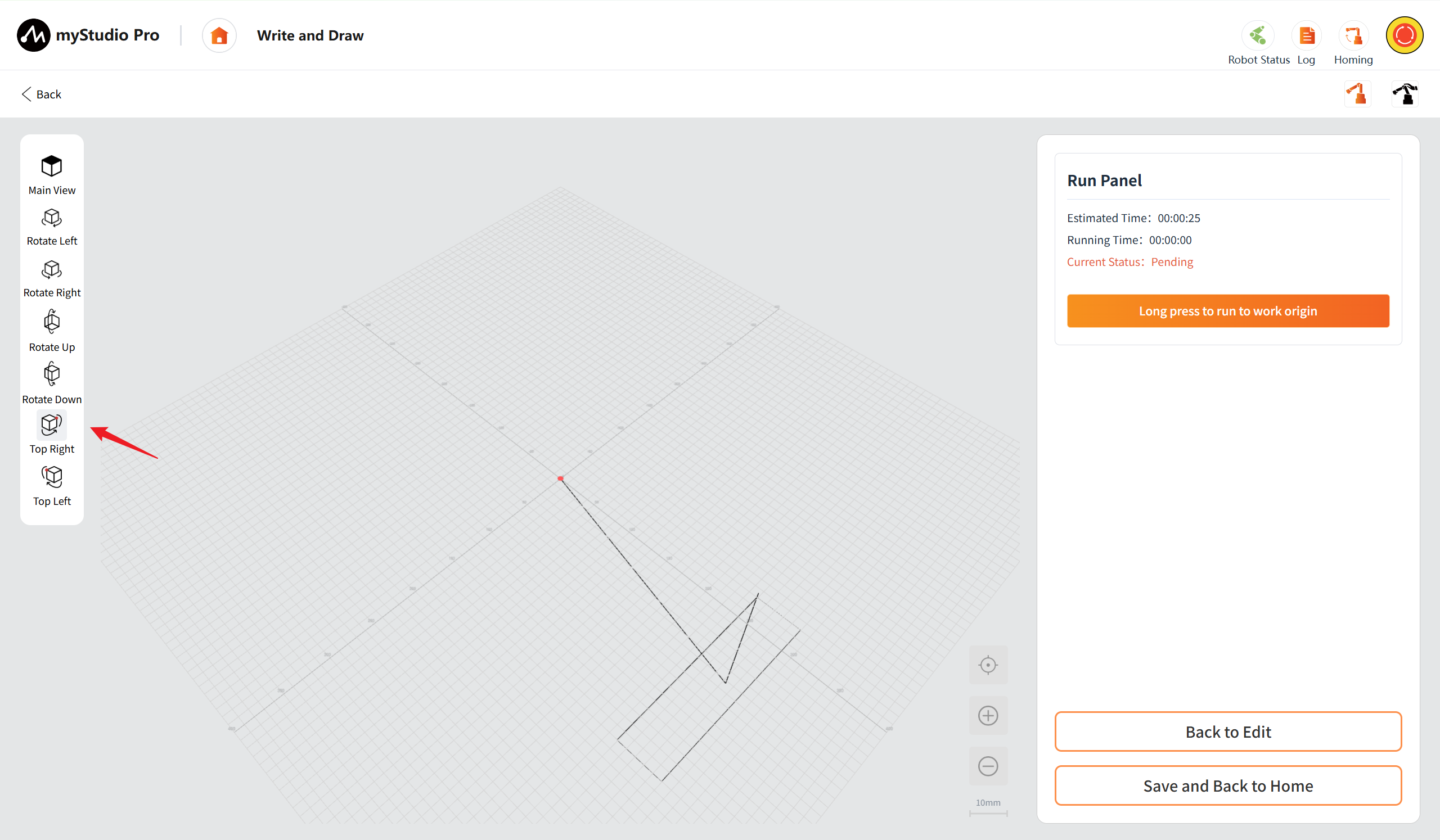
Top Left: After clicking the button, the viewing center will be quickly positioned to the upper left point of the work area.
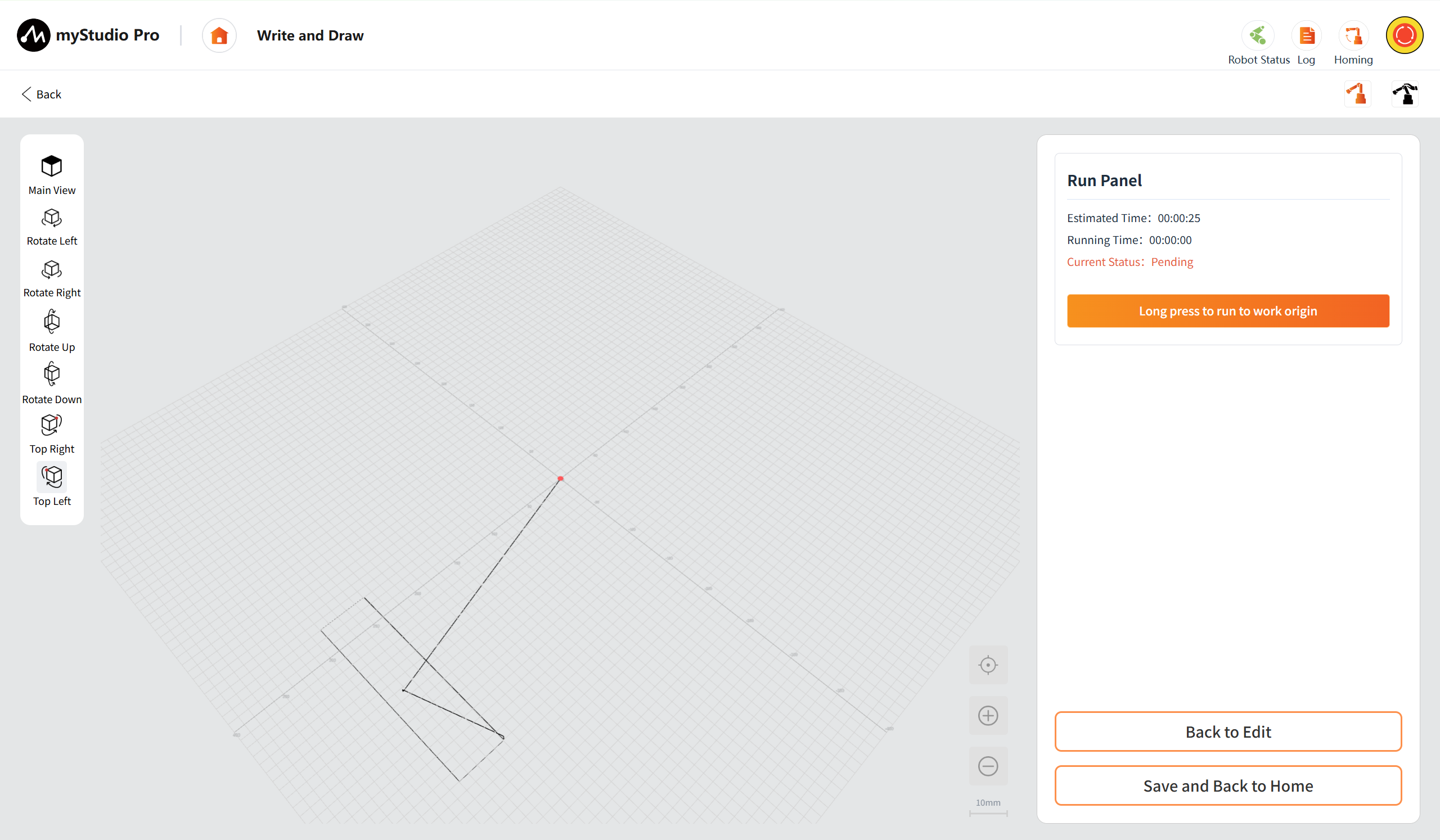
Integrates multi-directional view adjustment buttons (main view, rotation, positioning), allowing for free switching of viewing angles and enabling detailed examination of the trajectory from any perspective.
3D Processing Trajectory Preview Area
Renders the processing trajectory of the current G-code file in a three-dimensional form. The circular boundary clearly indicates the processing range that the robotic arm can reach. It supports operations such as zooming, rotating, and translating, and dynamically displays the grid scale.
The mouse can be used to drag for perspective movement, and the scroll wheel can determine the center point for zooming in and out.
Calibration: Click the "Calibration" button to restore the view to the default main perspective and the zoom ratio to the default value (10mm/grid) .
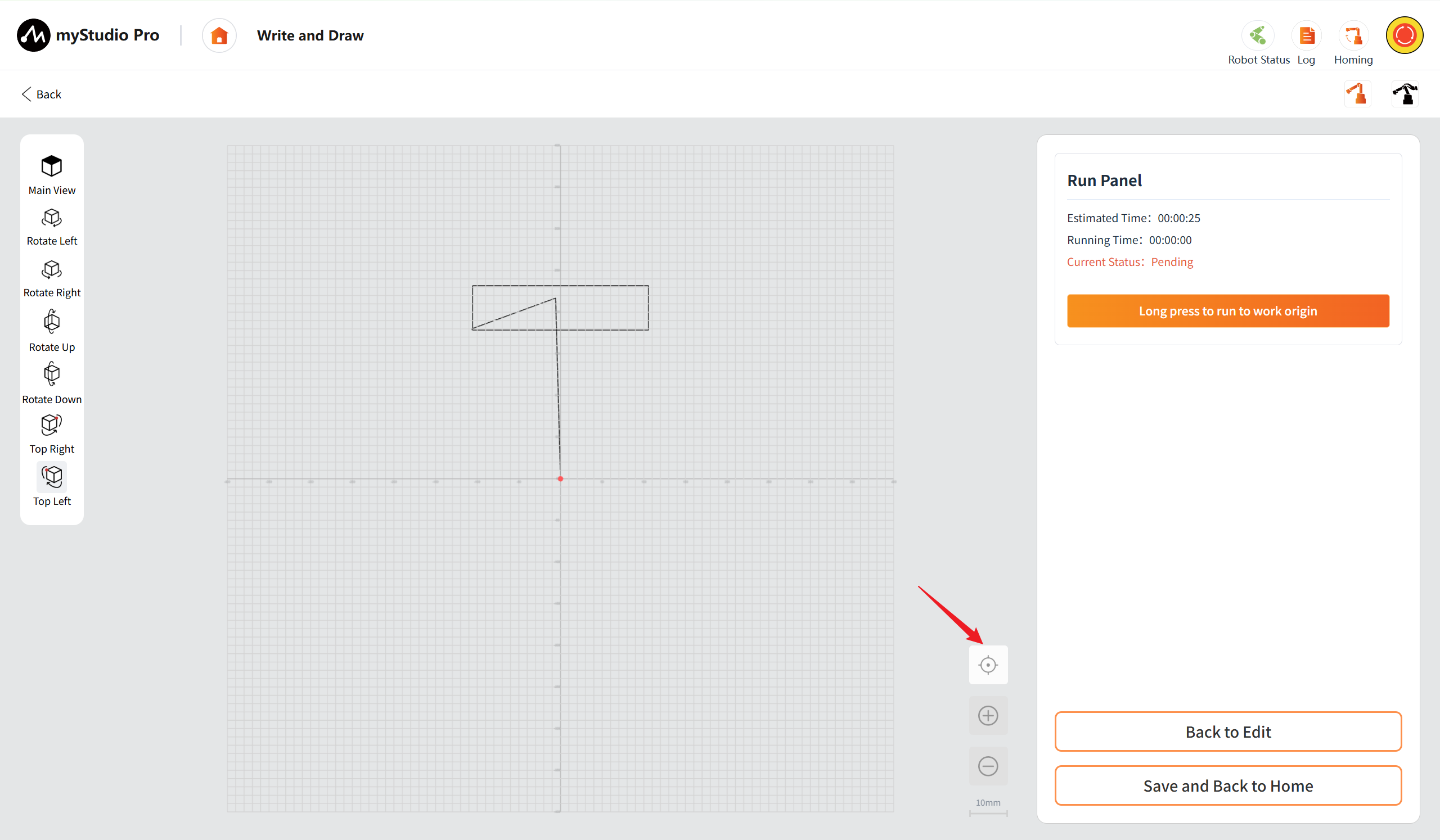
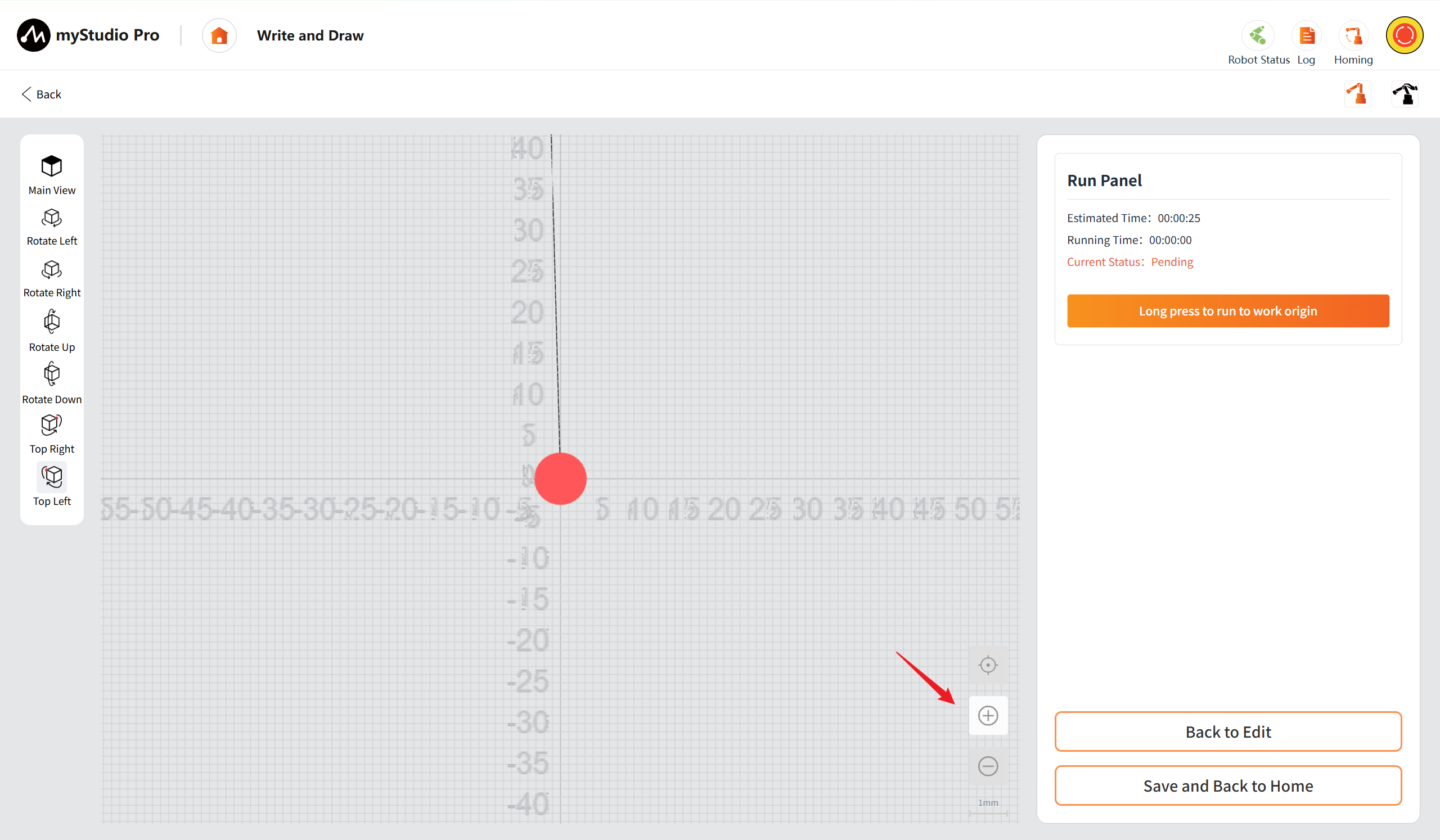
Zoom In: Click the "Zoom In" button once to increase the view level by one step. The scale will switch to a smaller value according to the preset sequence (for example, from 10mm/interval to 5mm/interval). Support for continuous clicks to gradually zoom in to the minimum scale of 1mm/interval. Once the minimum scale is reached, clicking the button will have no effect.
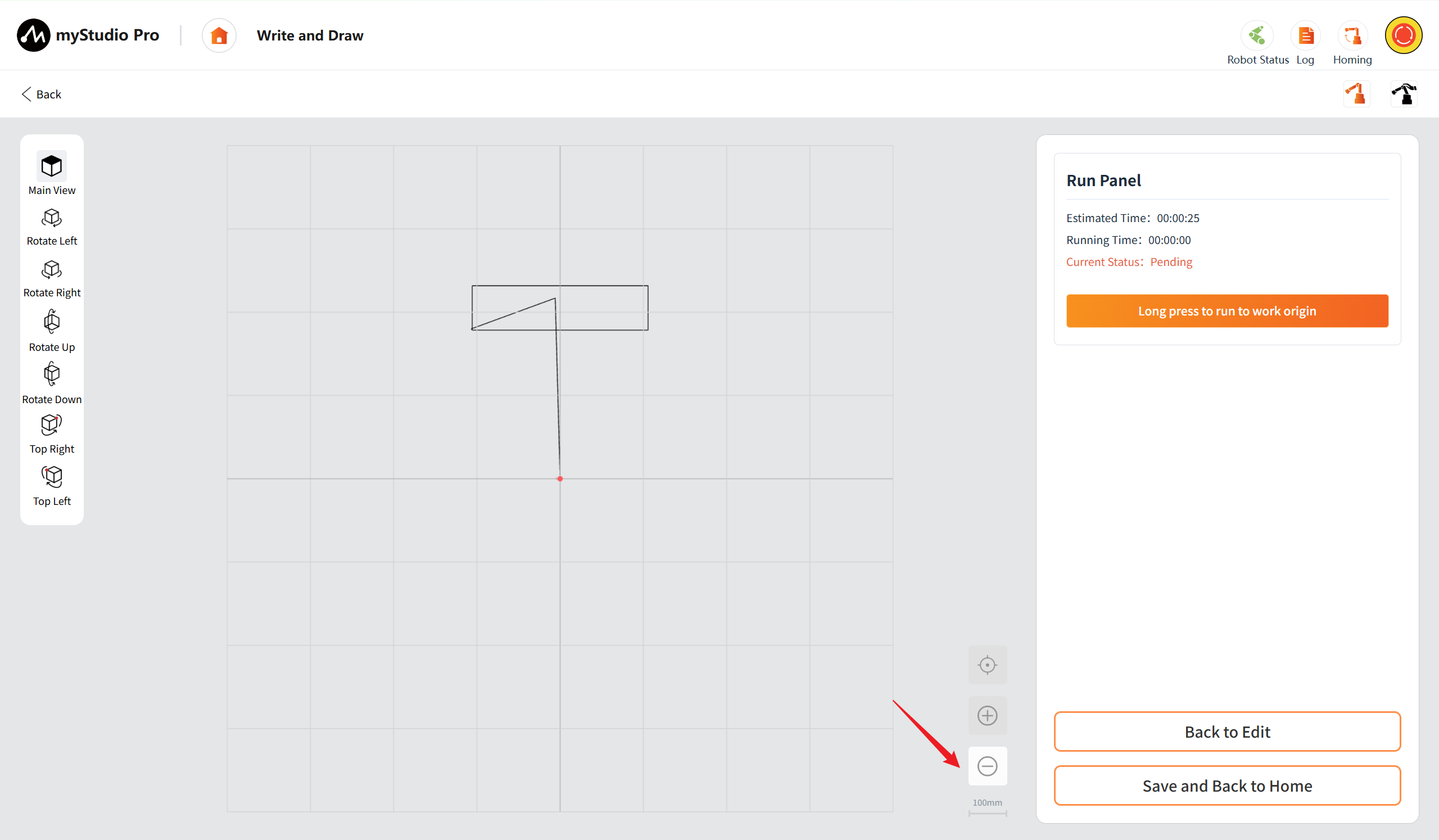
Zoom out: Click the "zoom out" button once, the view is scaled down one level, and the scale scale is switched to larger values in a preset sequence (e.g., from 10mm/ cell to 50mm/ cell). Support for continuous clicks to gradually reduce to the maximum scale of 100mm/interval. Once the maximum scale is reached, clicking the button will have no effect.
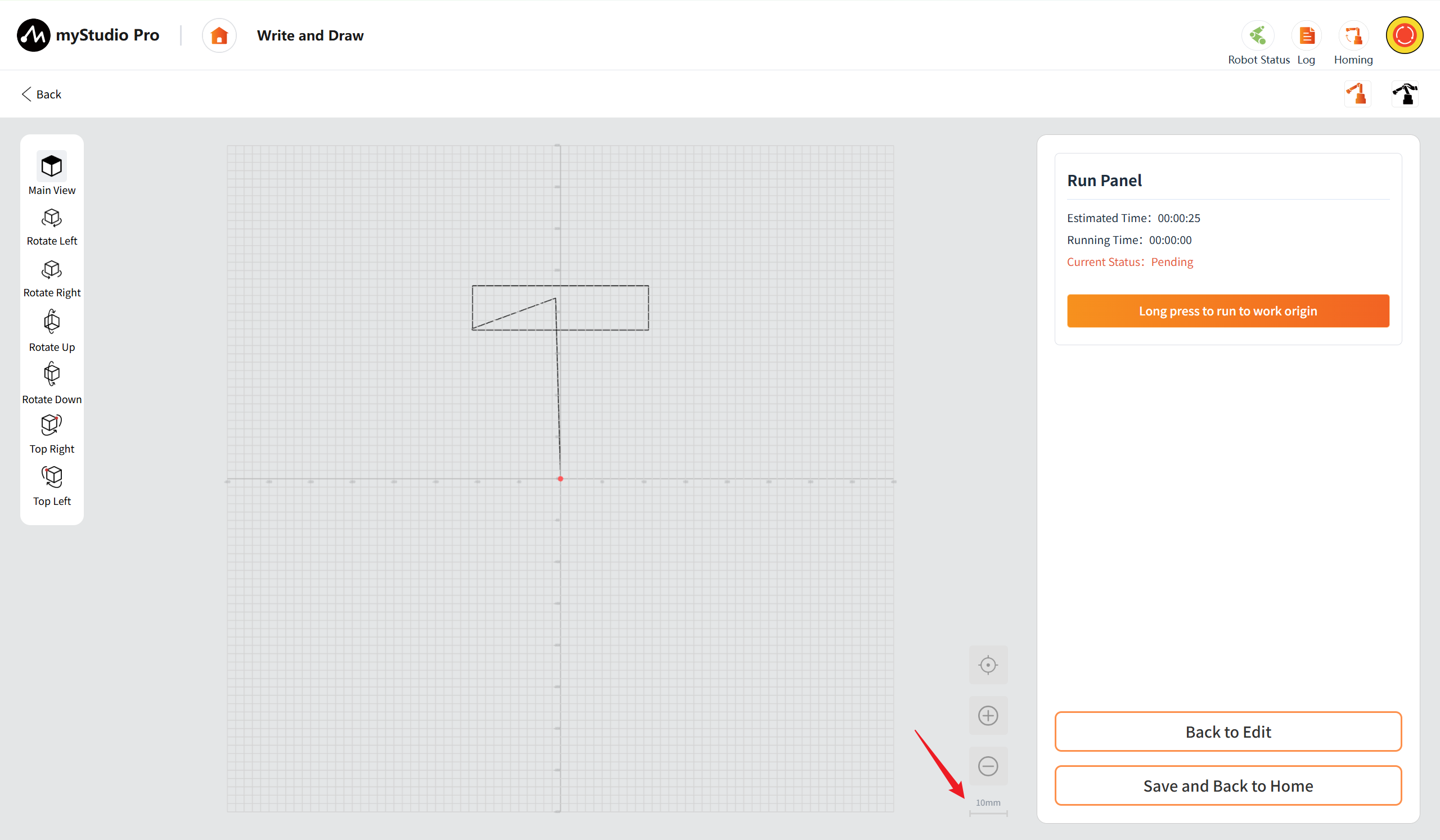
Scale: The current scale is displayed in the lower right corner, in the format "10mm", indicating the actual length represented by each small grid on the current grid.
Right debugger
The operation panel supports debugging runs. If any errors are found during the debugging run, you can return and make adjustments for editing. Once the processing file is confirmed to be correct, it can be saved and returned to the main interface.
Long press to run to work origin: After pressing the button, the robotic arm will move to the preset work origin. Once it reaches the original position, the buttons for running, pausing, and stopping will be displayed.
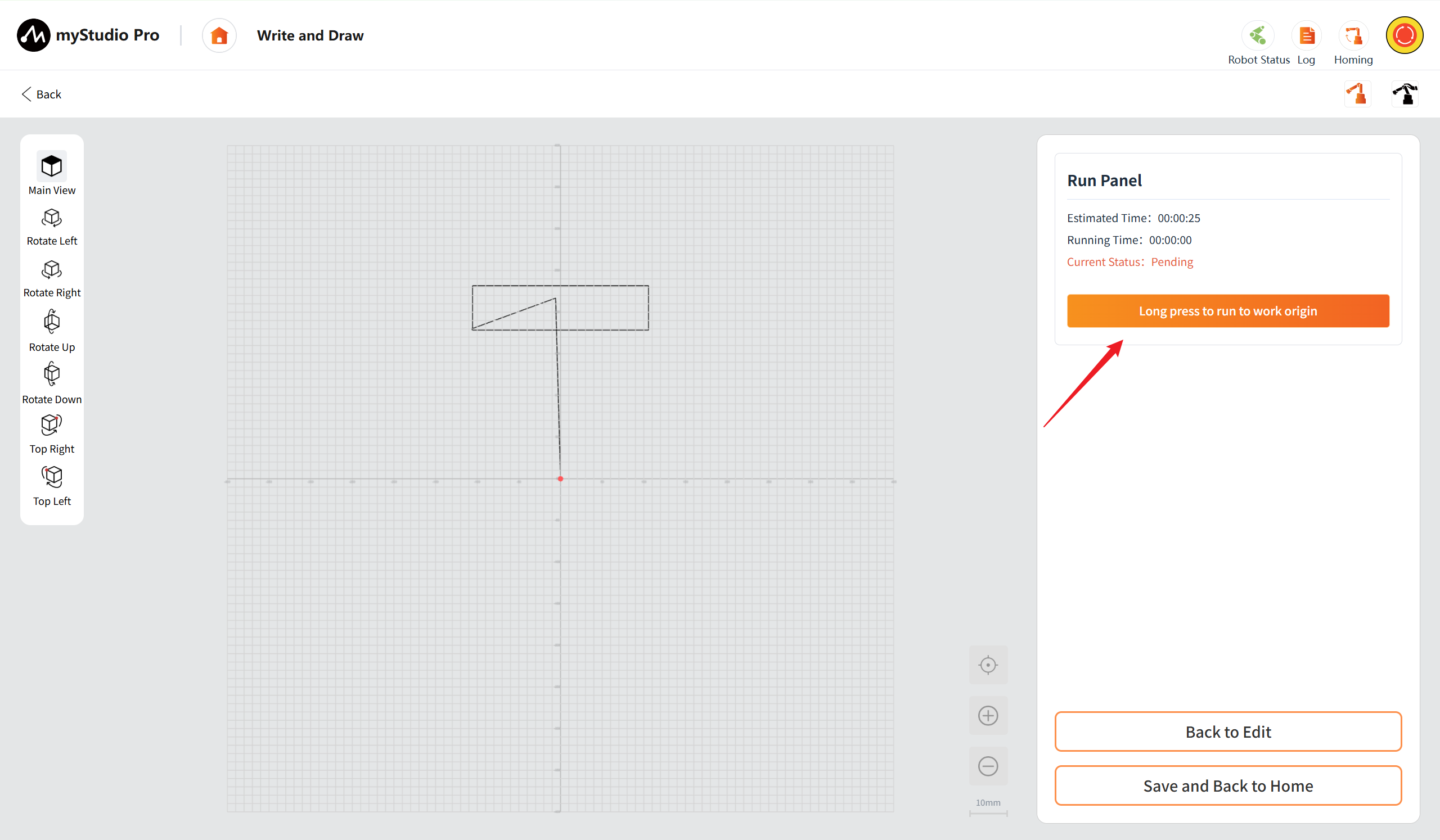
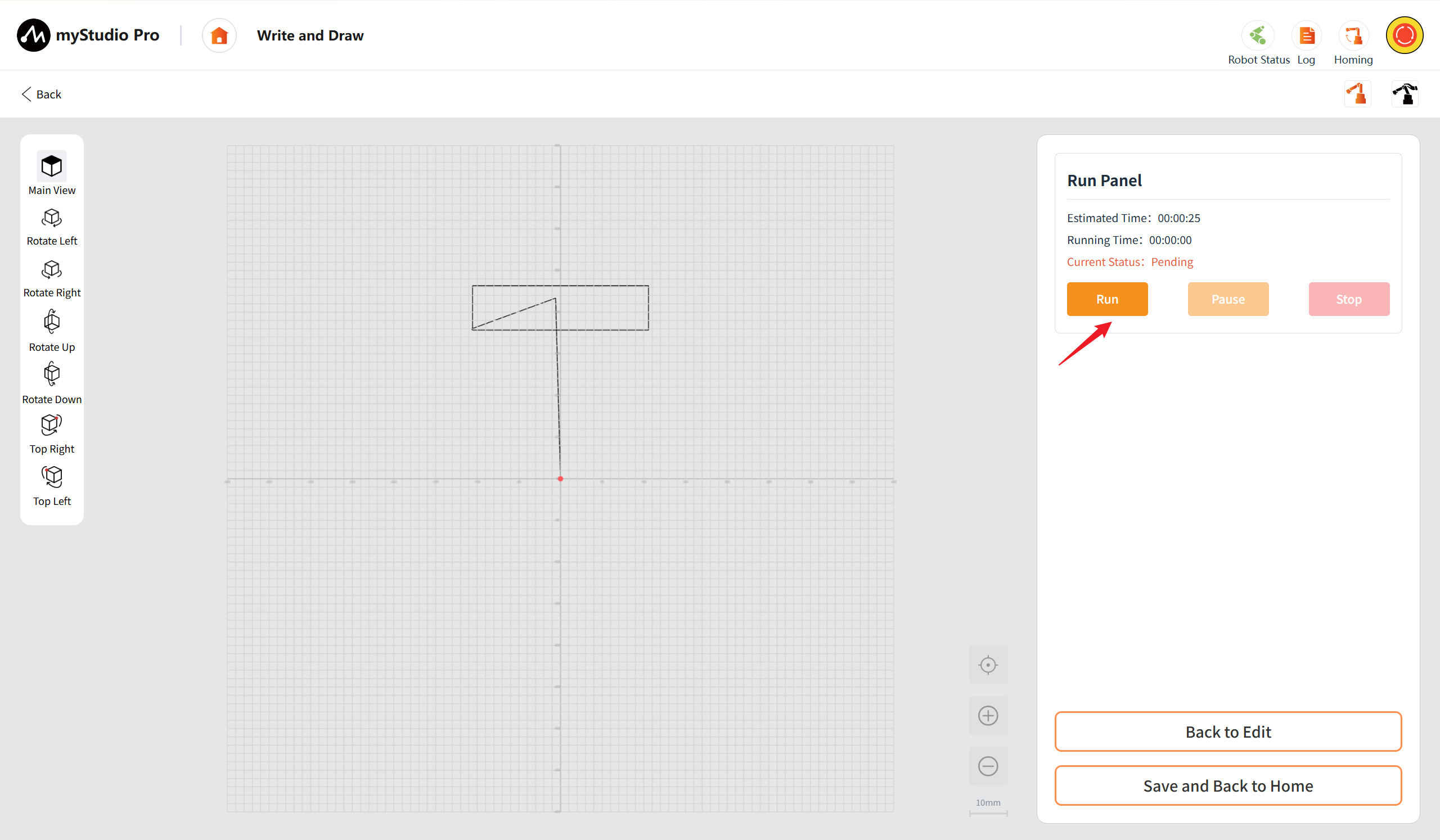
Run: After clicking the Run button, the robotic arm starts to process the file. The running time begins to be counted, the current status changes to "Running", the Run button turns to be disabled, while the Pause button and the Stop button become enabled.
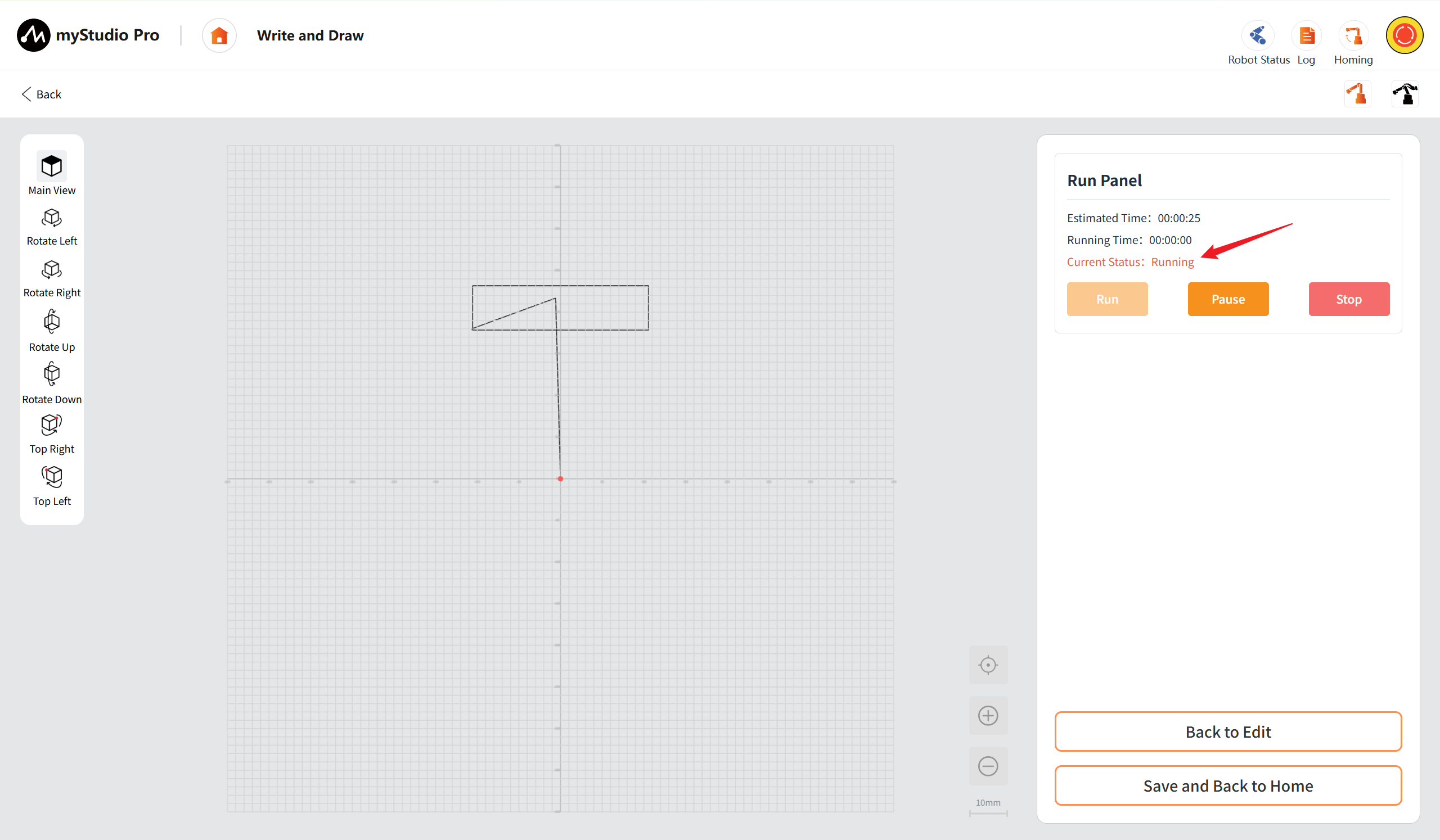
Pause: After clicking the pause button, the robotic arm stops running. The current status of the panel changes to "Paused", the run button becomes the "Resume" button, while the pause button becomes disabled and the resume button and stop button become enabled.
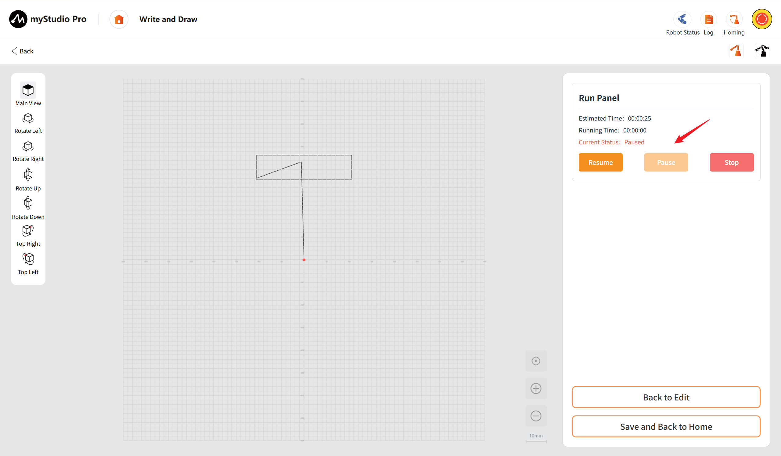
Resume: After clicking the "Resume" button, the robotic arm resumes its movement.
Stop: After clicking the stop button, the software stops issuing commands. The current status is "Stopped". Except for the Run button which is enabled, the pause button and the stop button are both disabled. The robotic arm will stop after completing the executed instructions. The current status of the operation panel is "Pending".
Back to Edit: Tap "Back to Edit" to return to the edit panel of "Write and Draw Workbench".
Save and Back to Home: Save and Return to Main Interface: After clicking the button, it will navigate to the "Main Writing and Drawing Interface", and the G-code file will be automatically added to the beginning of the file list on the main interface and selected.
Quick Movement
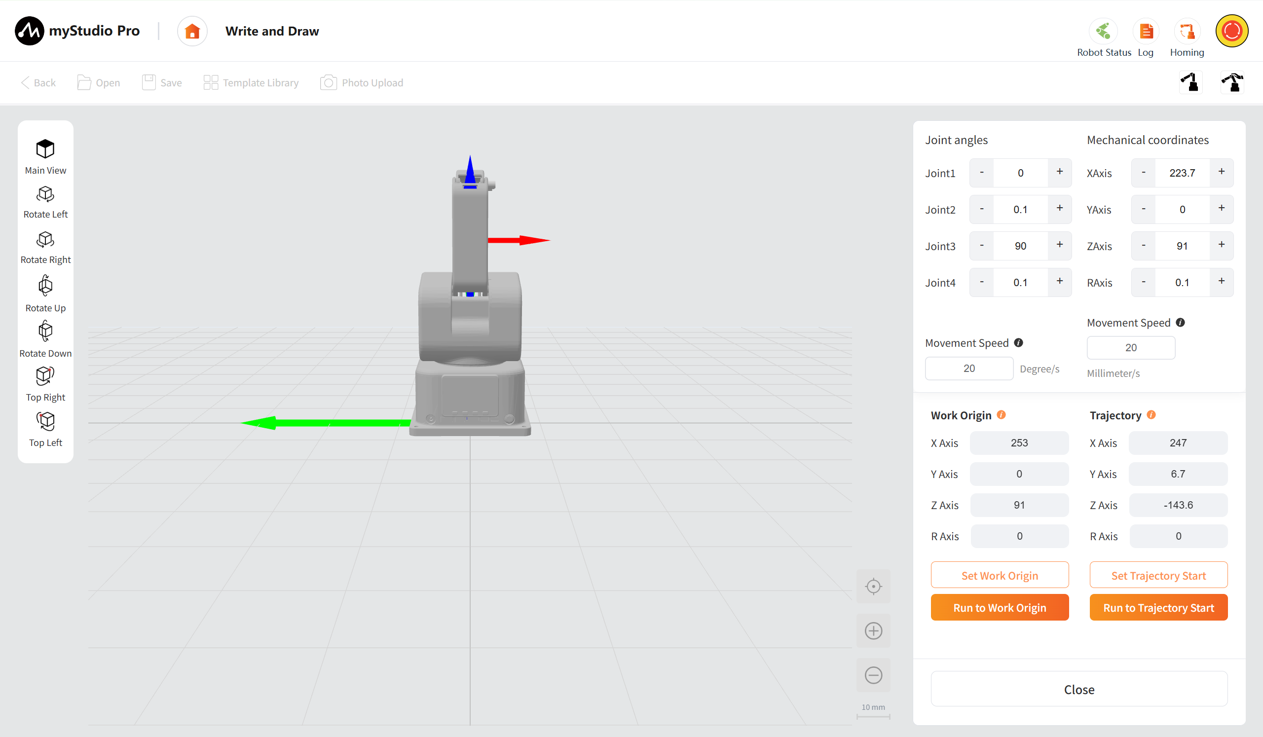
Left View Control Area
Provide the main view (restore default perspective), rotate left/rotate right/rotate up/rotate down (adjust the viewing angle), and left upper point/right upper point (quickly position the view center to the upper left point or upper right point of the work area), facilitating multi-dimensional inspection of the processing trajectory.
Main View: After clicking the button, the 3D preview area will be restored to its default initial perspective. The main view of this page is set as a top-down view by default.
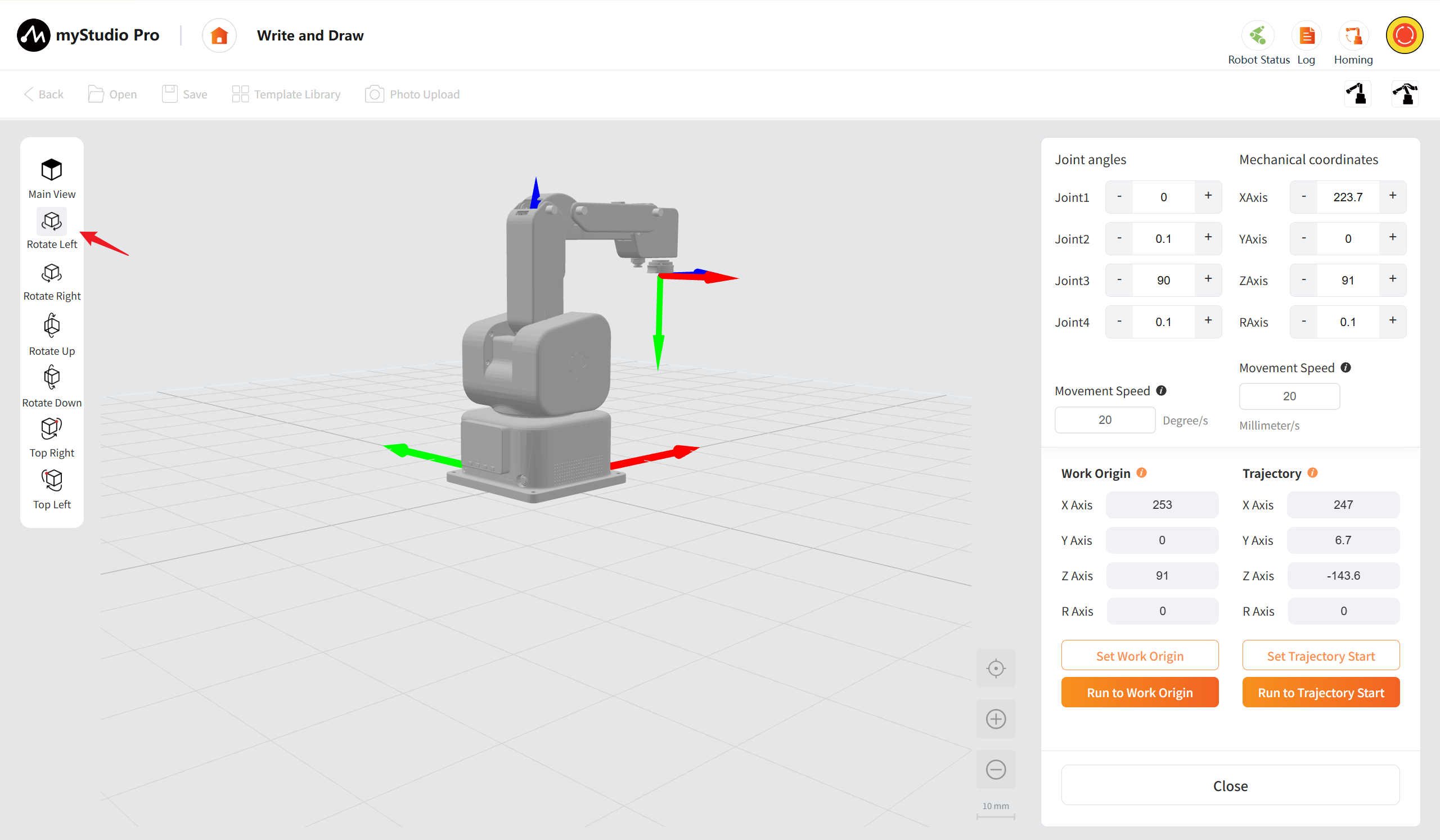
Rotate Left: Support single-click and long-press. Click to rotate 15 degrees, and long-press to rotate continuously to the left at a speed of 30 degrees per second until you release the button to stop.
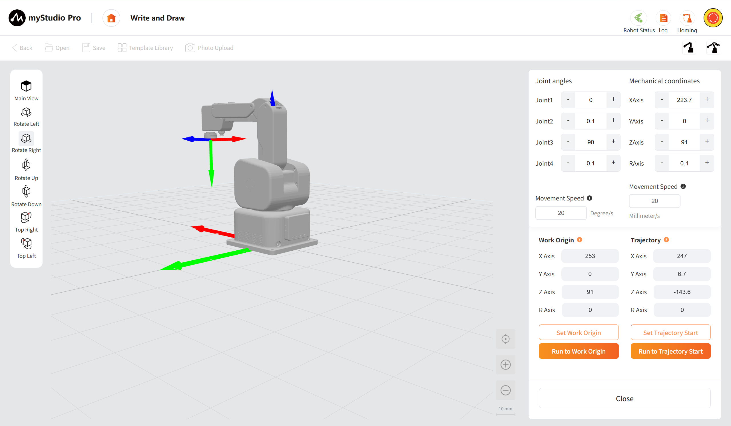
Rotate Right: Support single-click and long-press. Click to rotate 15 degrees, and long-press to rotate continuously to the right at a speed of 30 degrees per second until you release the button to stop.
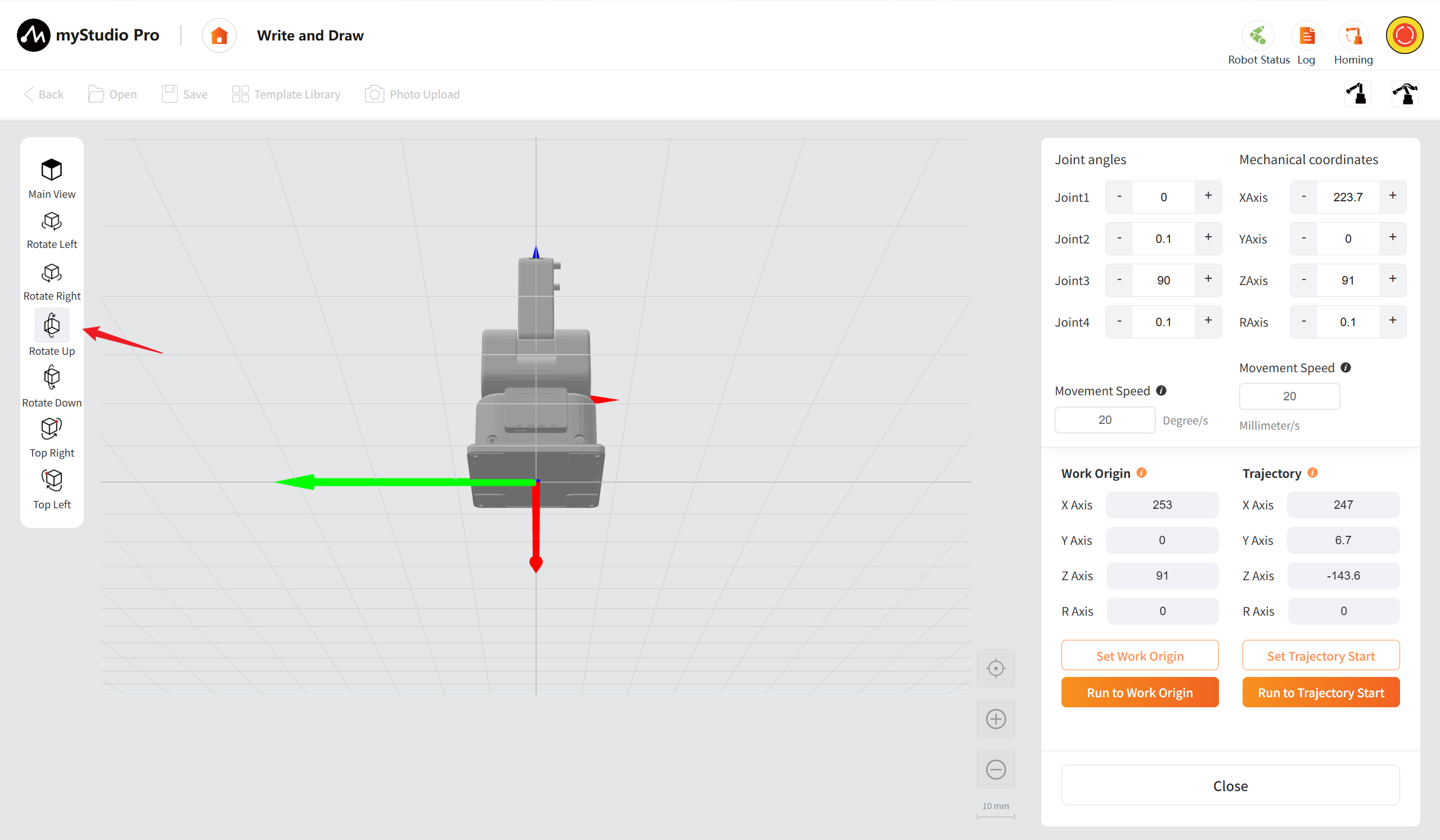
Rotate Up: Support single-click and long-press. Click to rotate 15 degrees, and long-press to rotate upwards at a speed of 30 degrees per second continuously until the button is released to stop.
Rotate Down: Support single-click and long-press. Click to rotate 15 degrees, and long-press to rotate downward at a speed of 30 degrees per second continuously until you release the button to stop.
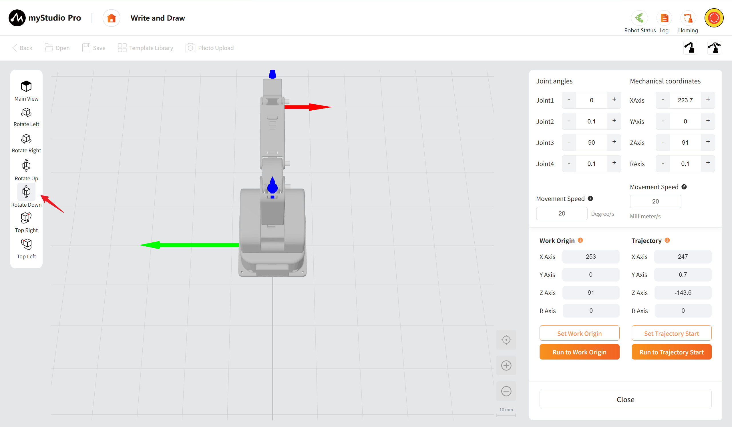
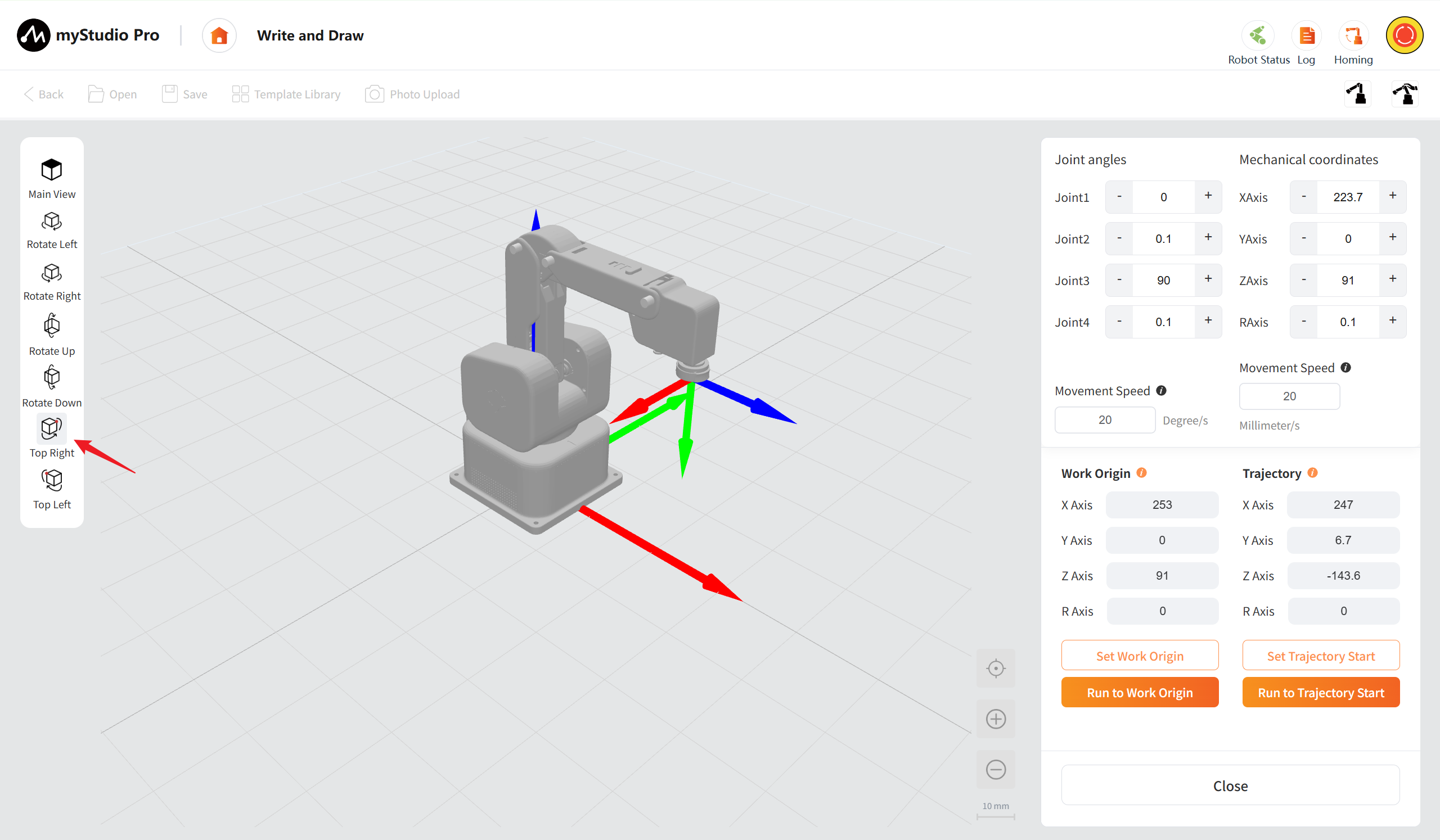
Top Right: After clicking the button, the viewing center will be quickly positioned to the upper right point of the work area.
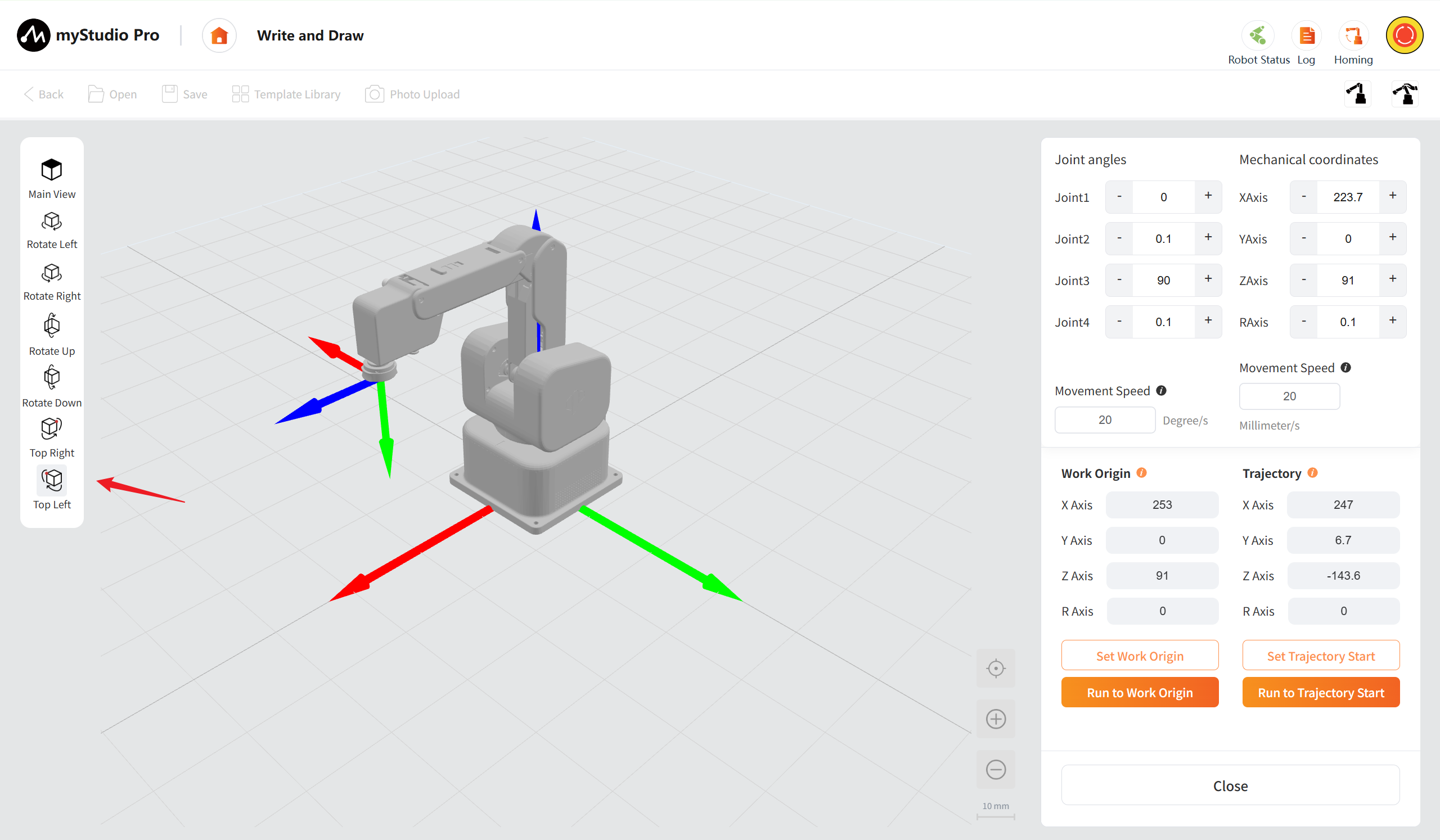
Top Left: After clicking the button, the viewing center will be quickly positioned to the upper left point of the work area.
3D Real-time Posture Panel
It is a 3D model used for visualization purposes to display the current posture of the robotic arm in real time.
Calibration: Click the "Calibration" button to restore the view to the default main perspective and the zoom ratio to the default value (10mm/grid) .
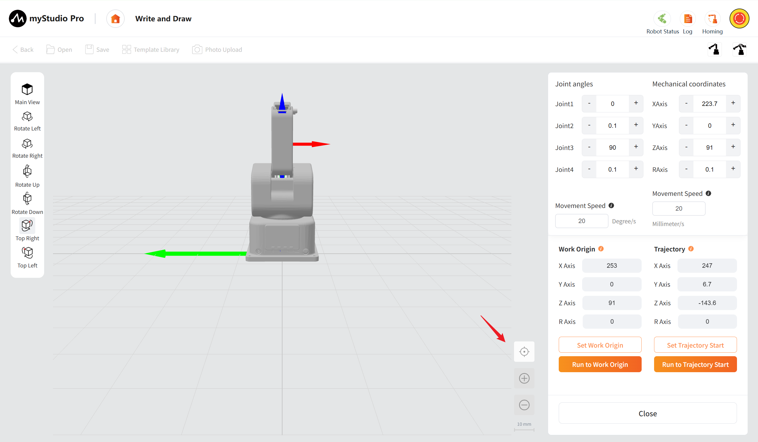
Zoom In: Click the "Zoom In" button once to increase the view level by one step. The scale will switch to a smaller value according to the preset sequence (for example, from 10mm/interval to 5mm/interval). Support for continuous clicks to gradually zoom in to the minimum scale of 1mm/interval. Once the minimum scale is reached, clicking the button will have no effect.
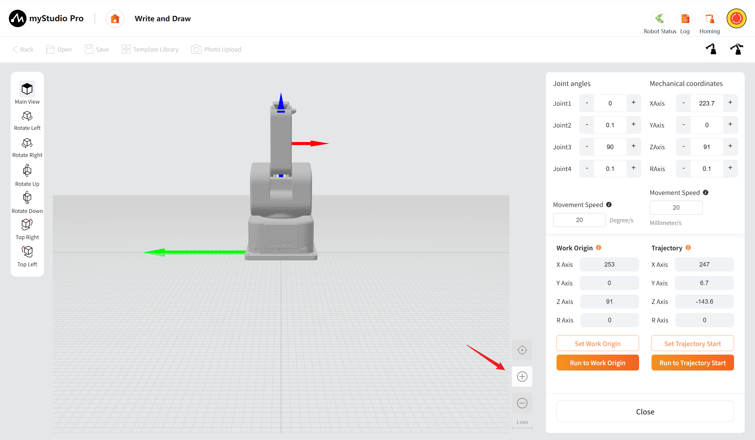
Zoom out: Click the "zoom out" button once, the view is scaled down one level, and the scale scale is switched to larger values in a preset sequence (e.g., from 10mm/ cell to 50mm/ cell). Support for continuous clicks to gradually reduce to the maximum scale of 100mm/interval. Once the maximum scale is reached, clicking the button will have no effect.
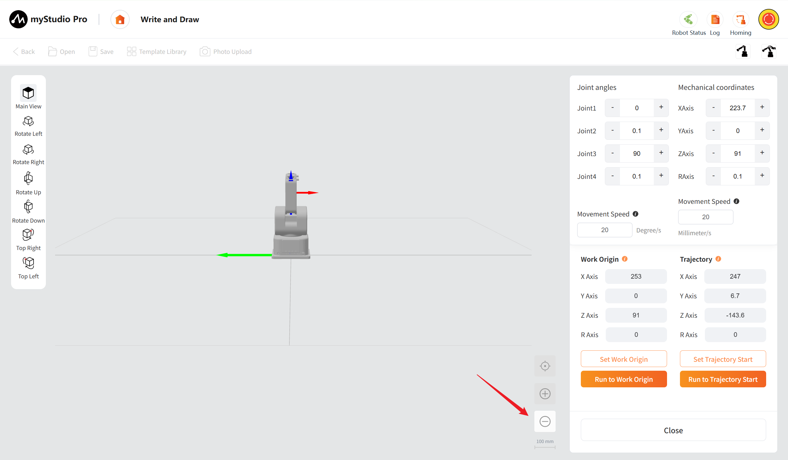
Scale: The current scale is displayed in the lower right corner, in the format "10mm", indicating the actual length represented by each small grid on the current grid.
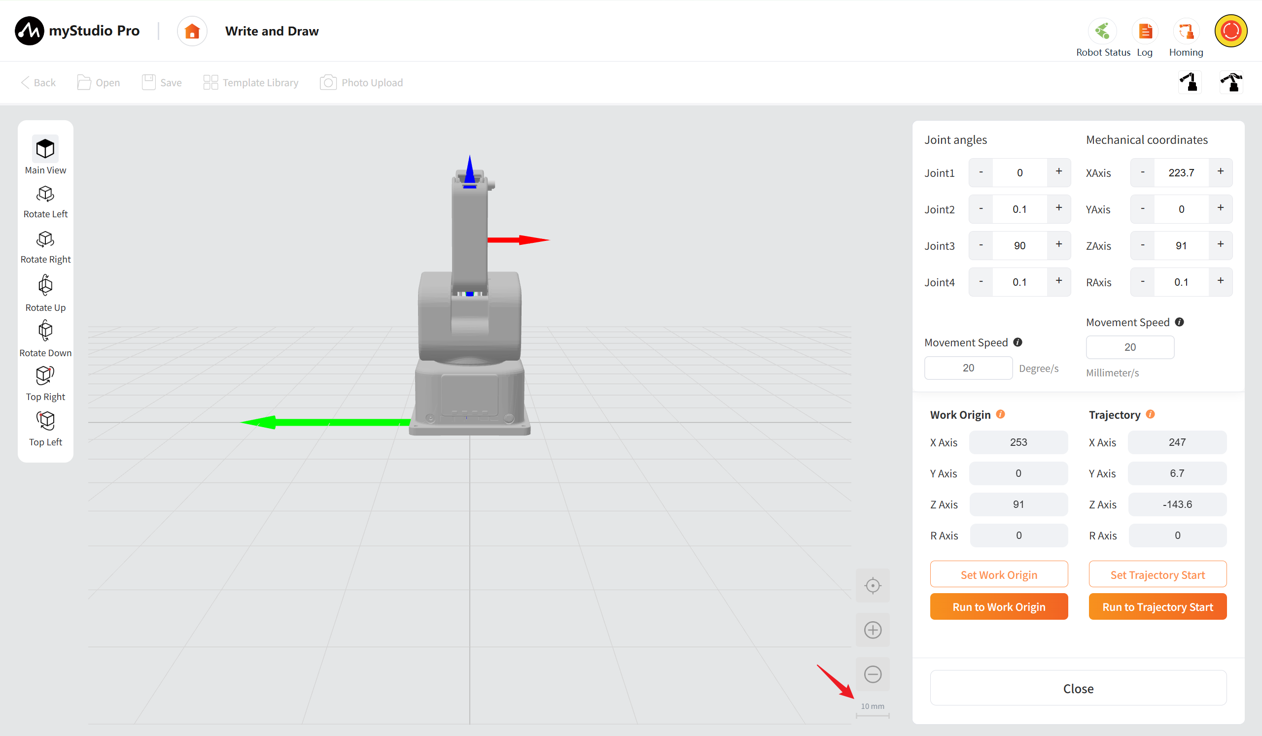
Angle coordinate control
Real-time display of joint angles, point-and-move to adjust joint angles, and long-press to set the speed. Mechanical coordinates: Real-time display of mechanical coordinates, point-and-move to adjust mechanical coordinates, and long-press to set the speed.
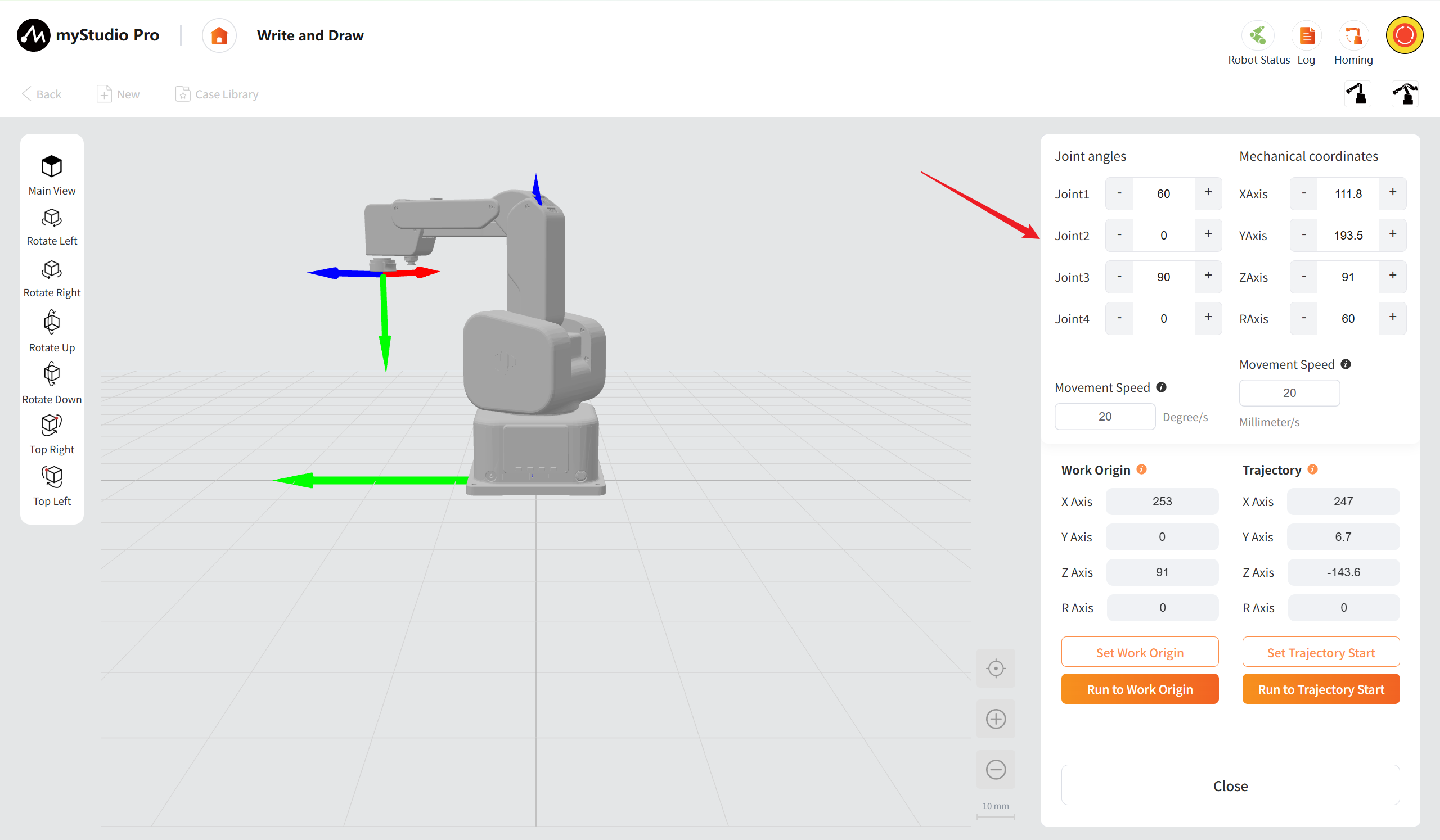
For a more detailed function description, please refer to the Debug Panel section
Work Origin
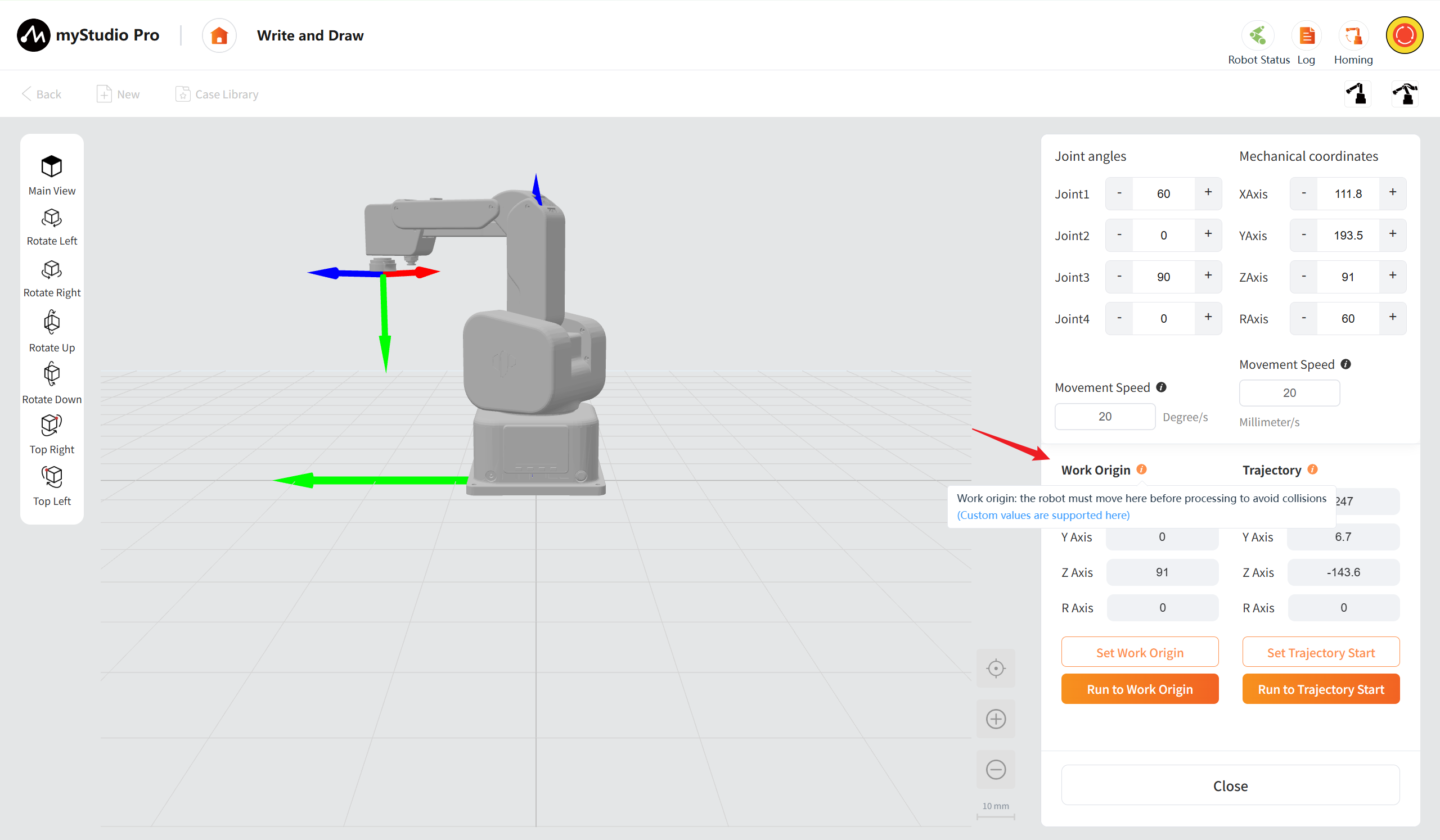
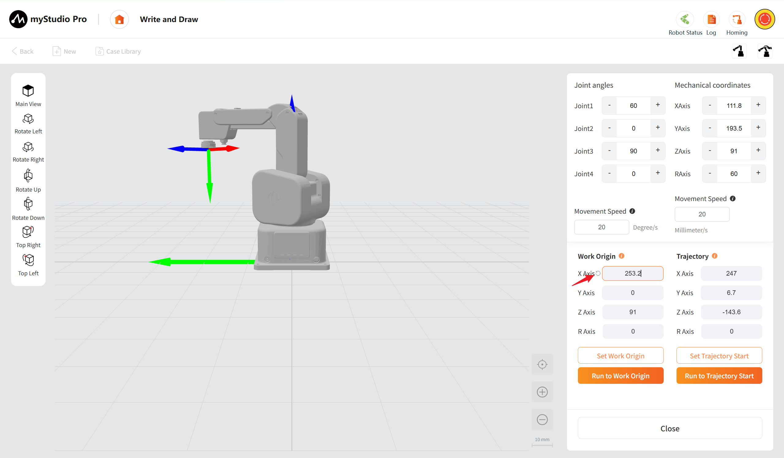
Display the coordinate values of the preset work origin. Click on the input box to modify the coordinate values of the work origin. After modification, a restore icon will appear as shown in the figure. Clicking on the restore icon will restore the preset coordinate values of the work origin.
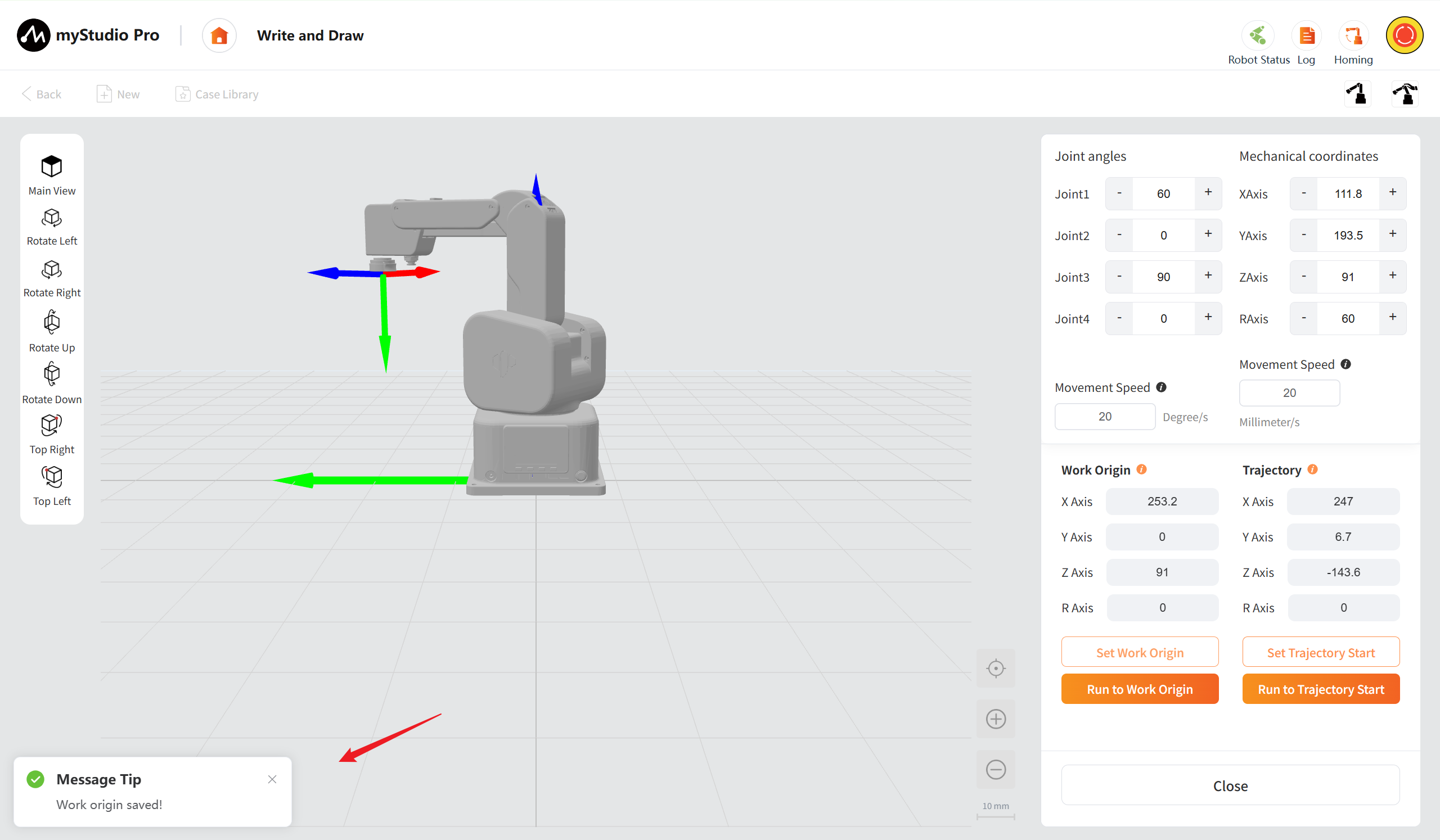
After clicking the "Set Work Origin" button, save the modified work origin coordinates.
After clicking the "Run to Work Origin" button, the robotic arm will move to the preset work origin.
Trajectory
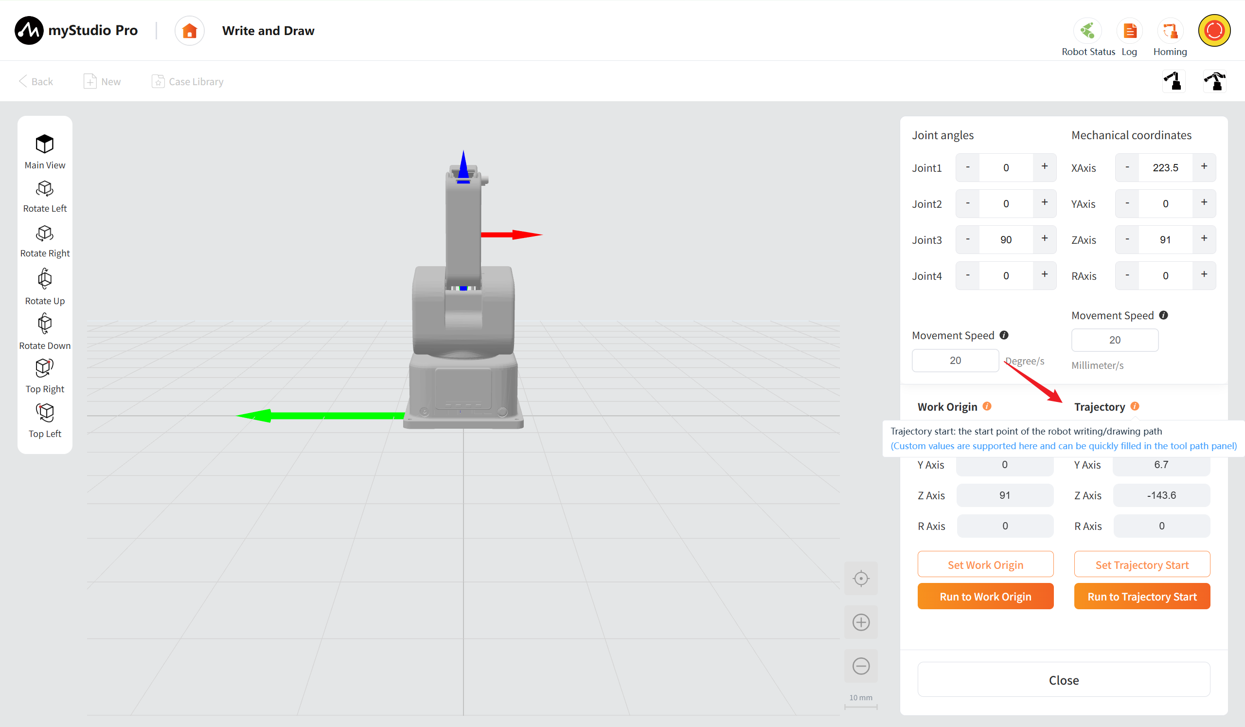
Display the coordinate values of the preset trajectory starting point. Click on the input box to modify the coordinate values of the trajectory start point. After modification, a restore icon will appear as shown in the figure. Clicking on the restore icon will restore the preset trajectory starting point coordinate values.
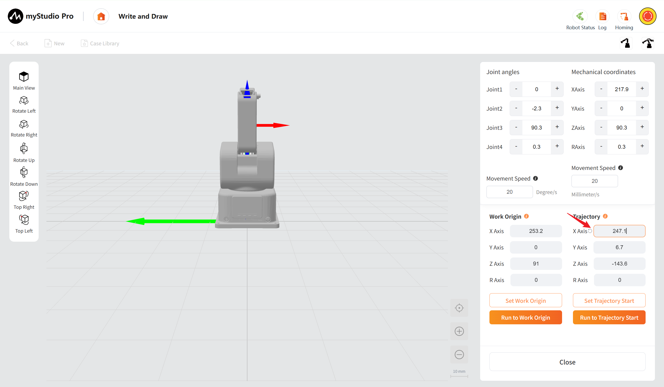
After clicking the "Set Trajectory Start" button, save the modified trajectory start point coordinates.
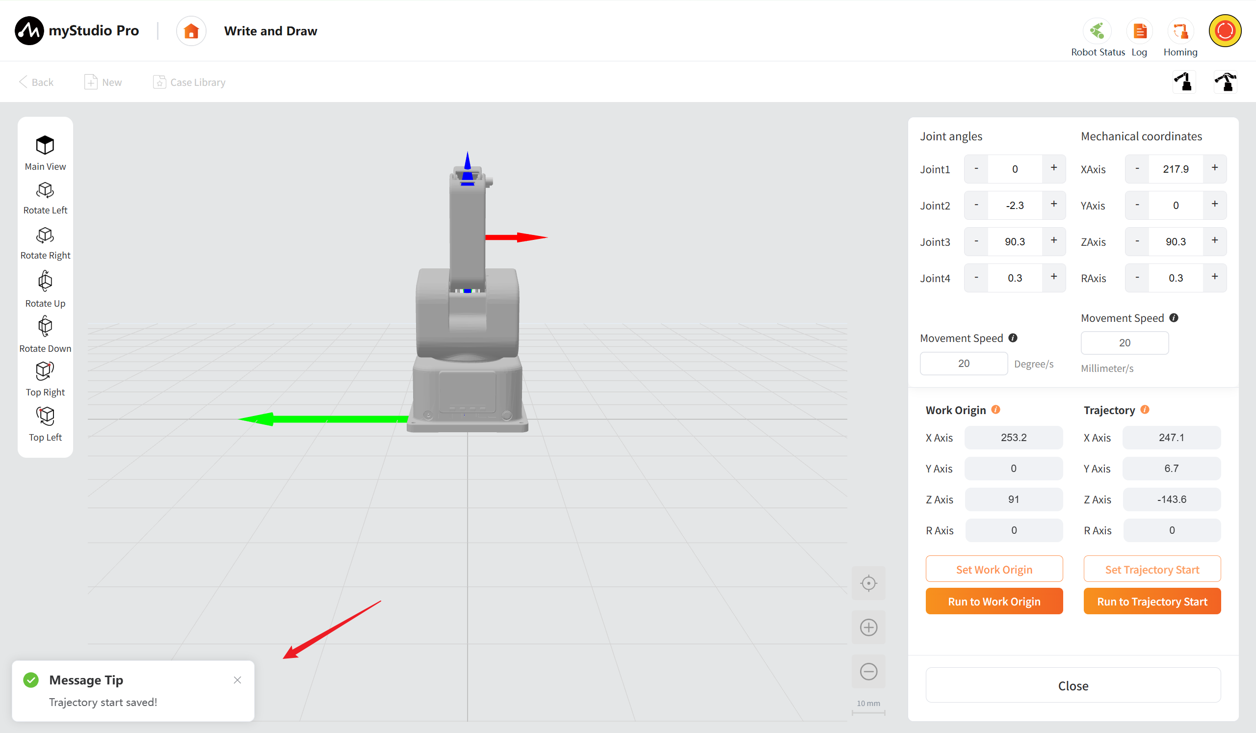
After clicking the "Run to Trajectory Start" button, the robotic arm will move to the preset starting point of the trajectory.
Note:
- If the work origin is modified but the save button is not clicked, when the "Close" button or the "Run to Work Origin" button is clicked, a pop-up window will appear asking whether to save.
- If the trajectory start point is modified but the save button is not clicked, when the "Close" button or the "Run to Trajectory Start Point" button is clicked, a pop-up window will appear asking whether to save.
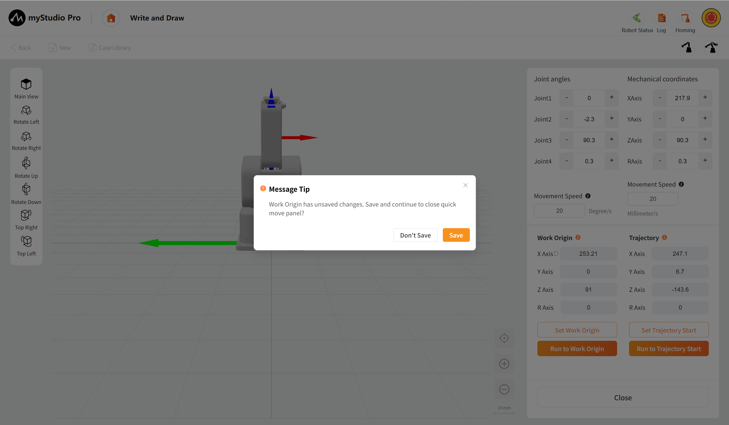
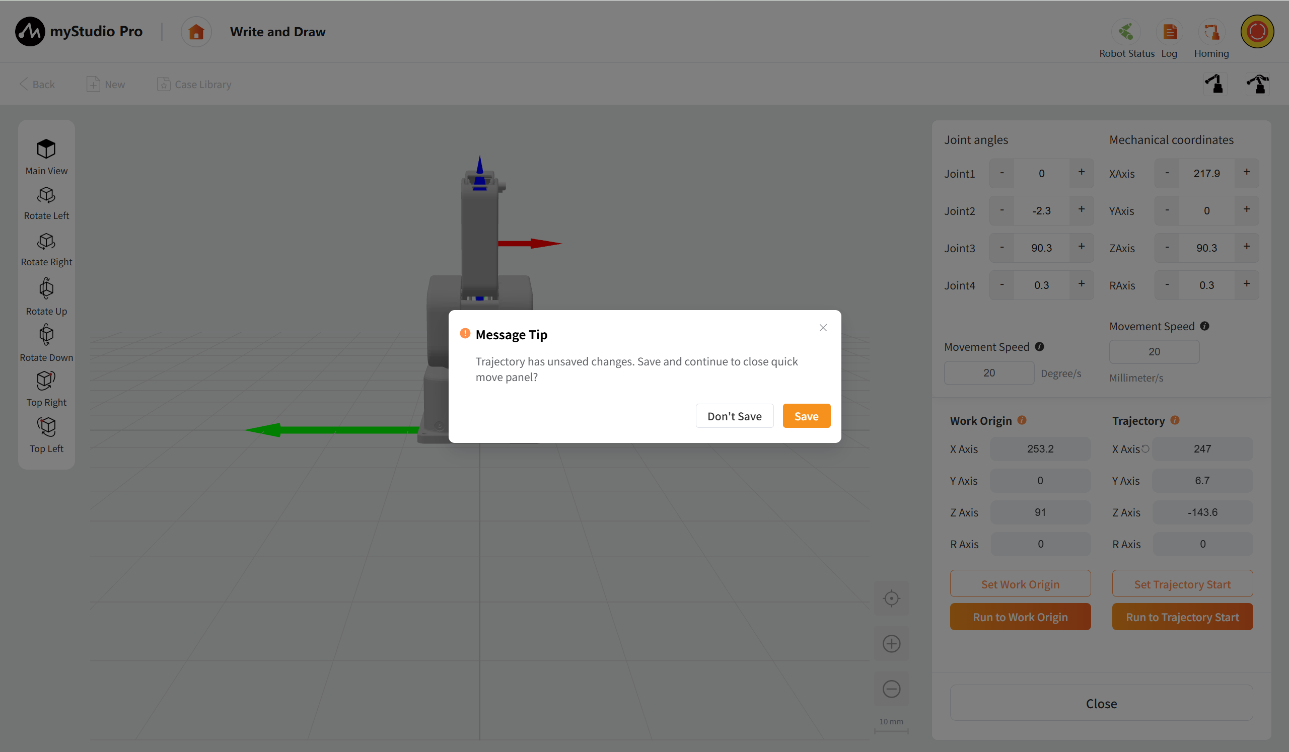
Clicking "Confirm" will save the modified data settings; otherwise, the data will not be saved and will automatically revert to the values before the modification.
Laser Engraving
The function interaction is consistent with writing and drawing. You can read the detailed contents of writing and drawing.