IO control
Both the M5Stack-basic at the bottom of the robotic arm and the Atom at the end have pins. The high and low levels of these pins can be set through IO control to operate tools such as pumps
Note: When starting RoboFlow, set the output pin level to low level uniformly. For the input and output pin numbers of various robot arm types, please refer to the instruction table below:
Table of input and output pin descriptions for the bottom M5Stack-basic:
| Robot Arm Model | Input Pin Number | Output Pin Number |
|---|---|---|
| myCobot 280-M5 | 35、36 | 2、5、26 |
| myCobot 320-M5 | 35, 36 | 5, 15 |
| myPalletizer 260 | 35, 36 | 2, 5, 26 |
Description table of terminal Atom input and output pins:
| Robot Arm Model | Input Pin Number | Output Pin Number |
|---|---|---|
| myCobot 280-M5 | 19, 22 | 23, 33 |
| myCobot 280-Pi | 19, 22 | 23, 33 |
| myCobot 320-M5 | None | None |
| myCobot 320-Pi | None | None |
| myPalletizer 260 | 19, 22 | 23, 33 |
1 I/O Interface IO Control
1.1 Enter the RoboFlow program editing interface, select Tools --> Basic Settings --> Select I/O (For how to enter the program editing interface, please refer to 6.2 Simple Usage of RoboFlow).
1.2 The I/O interface is shown in the figure below. Configuring output involves setting the M5Stack-basic output pin, while digital output involves setting the Atom output pin. Configuring input involves displaying the status of the M5Stack-basic input pin, while digital input involves displaying the status of the Atom input pin. The input pin display: when the input pin is at high level, the dot shown in the figure below will turn green, and low level is gray. (For which pin number config_out0, config_out1, etc. represent, please refer to the interface description table below.)
1.3 Output pin setting: Click the Test button to set the high and low voltage levels. If Test is displayed on the button, clicking it will set it to high voltage level. If Test is not displayed on the button, clicking it will set it to low voltage level. For specific details, refer to the prompt message after clicking the button. (When you click the Test button for the first time, a prompt will appear asking if you want to set the output IO to high voltage level. Selecting OK will remove the Test prompt from the button. When you click the button again, a prompt will appear asking if you want to set the output IO to low voltage level. Selecting OK will display the Test prompt on the button.) Please refer to the following figure for details:
Basic Configurable Interface Description Table:
|Configurable|myCobot 280-M5|myCobot 320-M5|myPalletizer 260|
|:--:|:--:|:--:|:--:|
onfig_out0|26|None|26
config_out1|5|15|5
config_out2|2|5|2
config_in0|36|36|36
config_in1|35|35|35
Atom Digital Interface Specification Table:
|Digital|myCobot 280-M5|myCobot 320-M5|myPalletizer 260|
|:--:|:--:|:--:|:--:|
digital_out0|5|15|5
digital_out1|2|5|2
digital_in0|36|36|36
digital_in1|35|35|35
2 Set interface IO control
If you need to cycle the high and low levels of the output IO or add other events in between, you can use this feature.
2.1 Run RoboFlow, enter the program editing interface by selecting "Tools" --> "Basic Settings" --> "Settings" (For details on how to enter the program editing interface, please refer to 6.2 Simple Usage of RoboFlow).
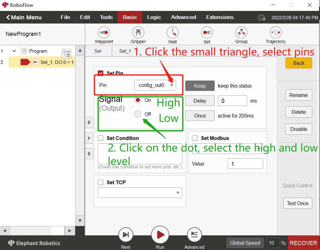
2.2 The setting interface is shown in the figure below. Click the dropdown box to select the output pin to be set (the dropdown box is in white font, which may be hard to see, but hovering over it will display the pin). Then select the high and low voltage levels (On--high, Off--low)
2.3 How to loop: For example, first set a certain output pin to high level in the first set interface, then add a wait interface to set a wait time of a few seconds, and finally add another set interface to set a certain output pin to low level. The specific steps are shown in the following figure: