Quick Move
before the start
1. Make sure the machine is powered on
2. Make sure the machine connection and communication are normal
3. Make sure the machine is in zero position
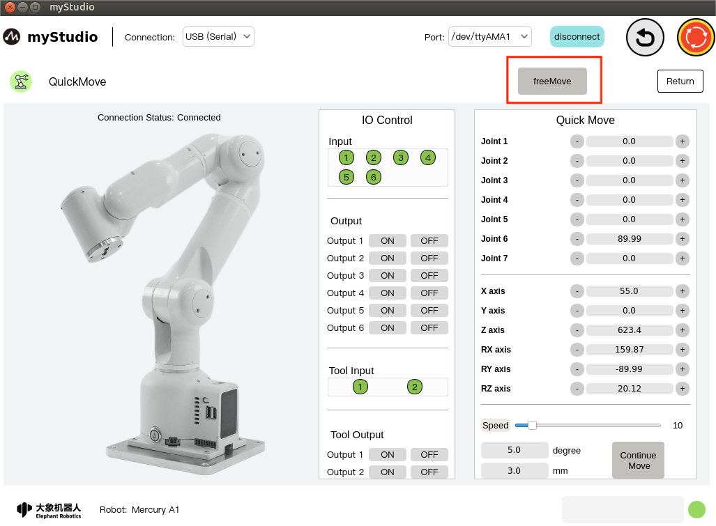
1 Interface introduction
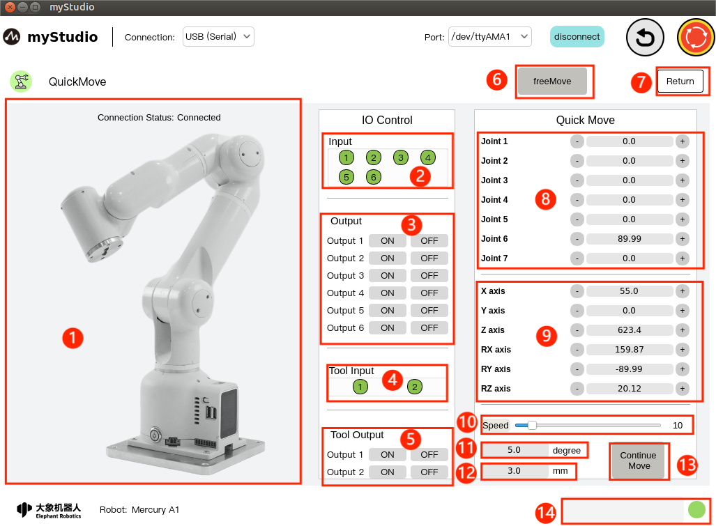
| serial number | Function introduction |
|---|---|
| 1 | Mercury A1 model diagram |
| 2 | The bottom IO pin numbers 1-6 are input and belong to the security module detection items |
| 3 | Bottom IO pin numbers 1-6, output, you can click the switch button to set the output |
| 4 | End IO pin number 1-2, input, belongs to the security module detection item |
| 5 | End IO pin number 1-2, output, used to control the adaptive gripper |
| 6 | Turn on free movement mode |
| 7 | Exit quick movement interface |
| 8 | Angle control, click the + - button to control the joint angle of the robot arm. The value represents the joint angle information of the current robot arm. You can also modify the value directly for joint control |
| 9 | Coordinate control, by clicking the + - button, coordinate control of the robotic arm. The value represents the current coordinate attitude information of the robotic arm. You can also modify the value directly for coordinate control |
| 10 | Set the movement speed of the robot arm, the default is 10 mm/s |
| 11 | Angle step, the angle value that increases or decreases each time when adjusting the angle |
| 12 | Coordinate step size, the coordinate value that increases or decreases each time when adjusting the coordinate posture |
| 13 | Turn on continuous movement mode |
| 14 | Safety module that detects robot status in real time |
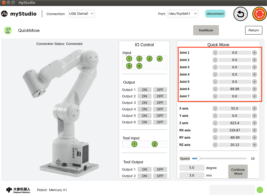
2 Angle control
In the angle control area, click the + - button to control the joint angle of the robotic arm. The value represents the joint angle information of the current robotic arm. You can also modify the value directly for joint control.
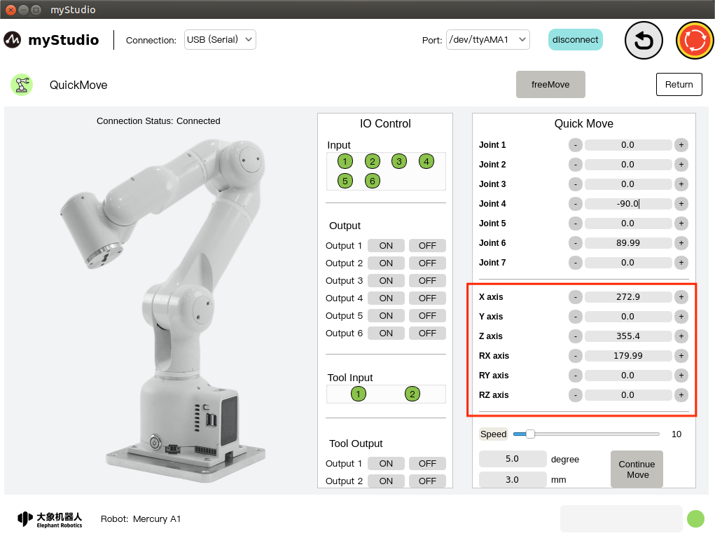
3 Coordinate control
Before using coordinate control, you need to move Joint 4 to an angle position of about -90.
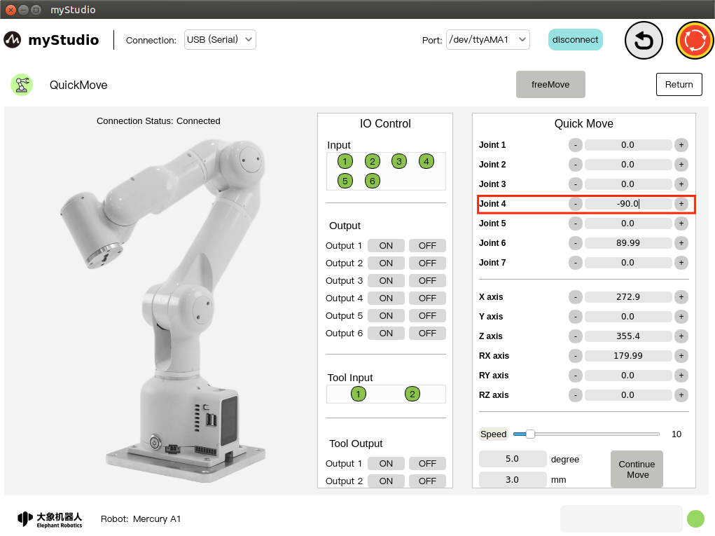
In the coordinate control area, click the + - button to control the coordinates of the robotic arm. The value represents the coordinate attitude information of the current robotic arm. You can also modify the value directly for coordinate control.
4 Free movement
Open the free movement mode by clicking the freeMove button. The color of the button will turn green, and the LED light panel at the end of the machine will turn yellow, indicating that the machine is in free movement mode. At this time, you can press and hold the end LED light panel to operate the machine. Drag to move.
The button color changes to green:
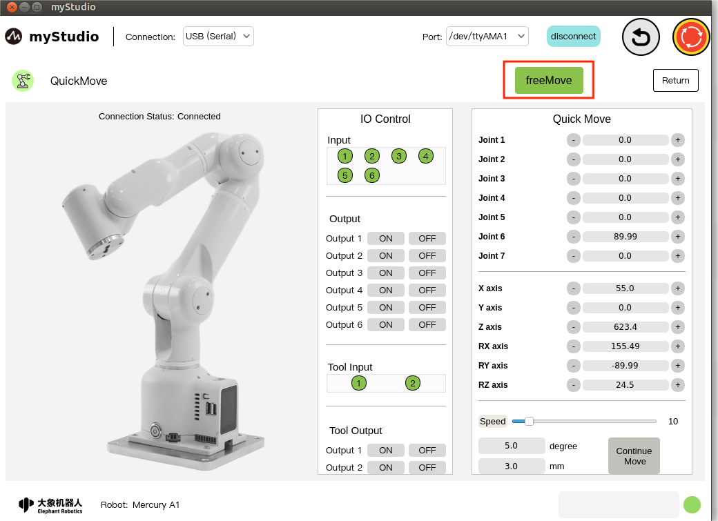
When the freeMove button is in the green state, clicking the button again means turning off the free move mode. At this time, the button color turns gray and the LED light panel at the end of the machine turns green.
5 Continuous movement
Turn on continuous movement mode by clicking the Continue Move button, which changes color to green. You can control the robot to continuously move at a specified angle by long pressing the + - button in the corresponding area, or control the robot to continue to move according to the specified coordinates or attitude value.
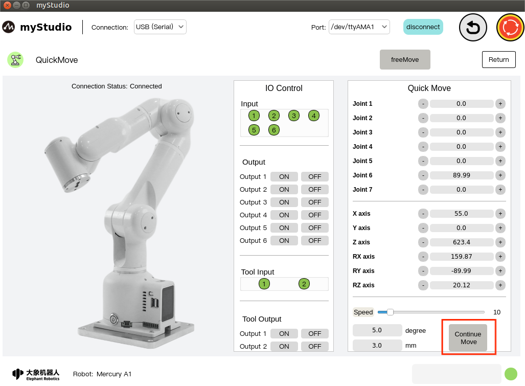
The button color changes to green:
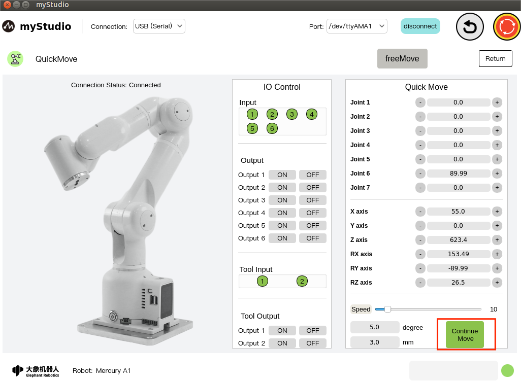
When the Continue Move button is in the green state, clicking the button again means turning off the continuous movement mode, and the button color turns gray.
Note: + - After each long press of the button for 3 seconds, you need to release the button, long press again, and then continue to operate and move continuously.
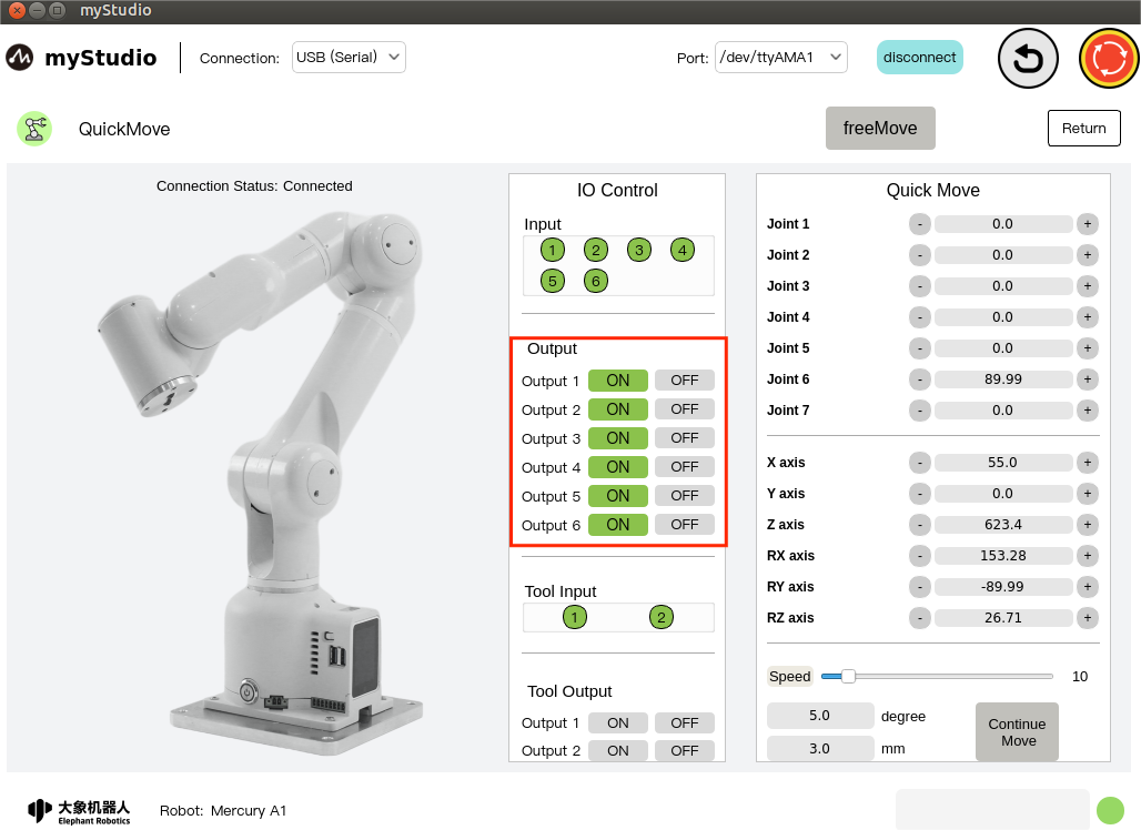
6 IO control
6.1 Bottom IO
Set the bottom IO pin number 1-6 output, the user can customize the control actuator. For example, you can customize the control of the gripper and suction pump.
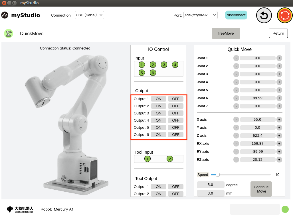
Click the On/Off button to set it.
6.2 End IO
Set the end IO pin number 1-2 output to control the adaptive gripper.
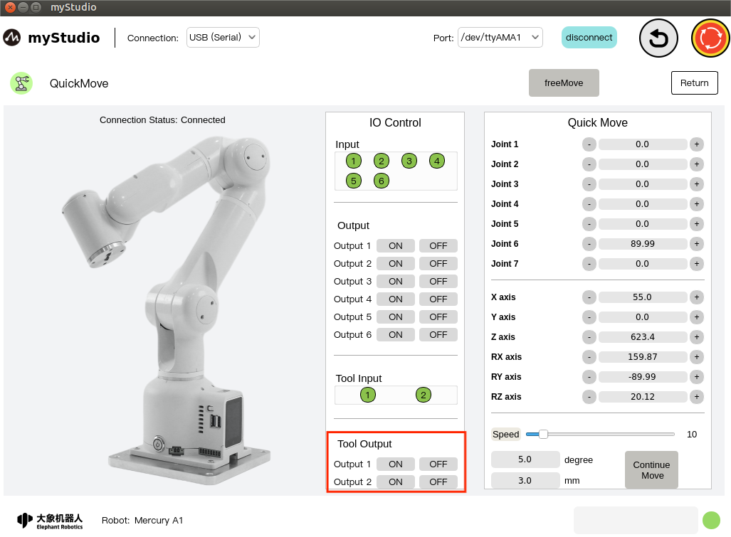
Turn on the adaptive gripper by clicking the On/Off button.
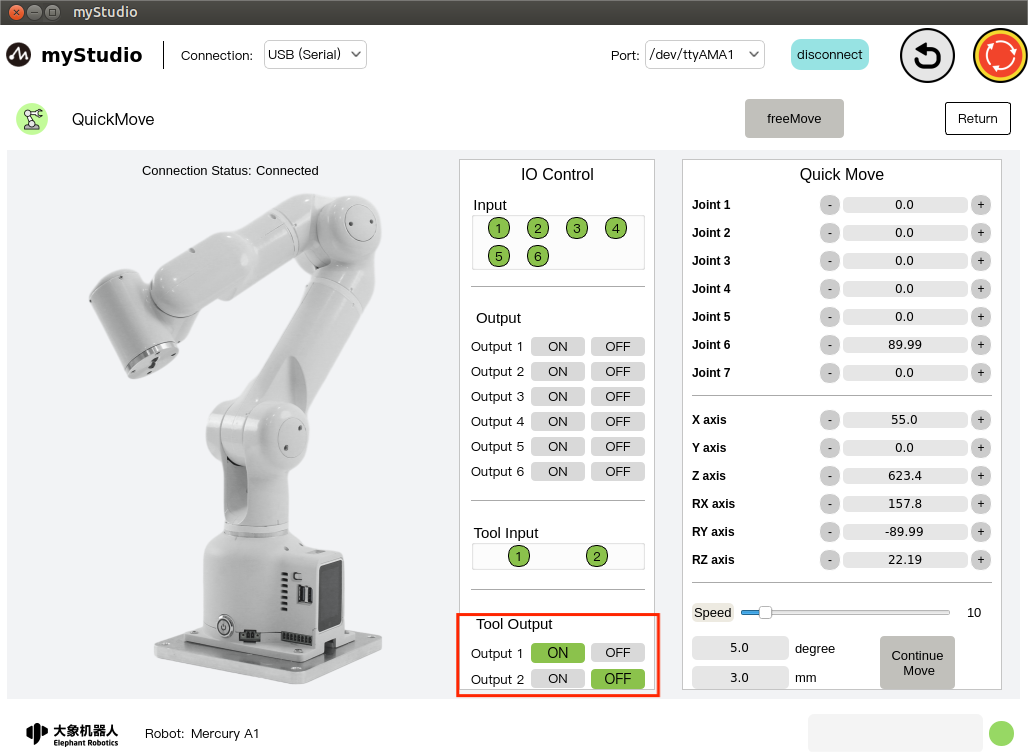
Turn the adaptive gripper off by clicking the On/Off button.
