13.4 Identify color blocks
This case uses the eye_to_hand mode, uses the camera to locate the color through opencv, frames the color blocks that meet the conditions, and calculates the spatial coordinate position of the block relative to the mechanical arm through the relevant points. Set a set of related actions for the manipulator and place it in different barrels according to the different colors of the identified blocks. In the following chapters, the code implementation process of the whole case will be introduced in detail.
一、Camera adjustment
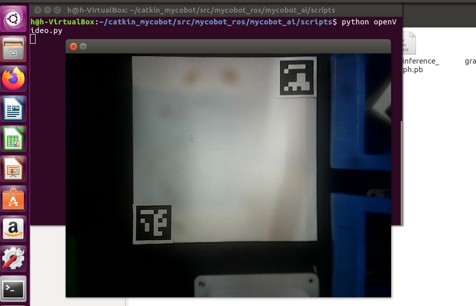
First, you need to use Python to run openvideo. Py under the mycobot_ai package. If the open camera is a computer camera, you need to modify cap_ Num, please refer to:matters needing attention Make sure that the camera completely covers the whole recognition area, and the recognition area is square in the video, as shown in the figure below. If the recognition area does not meet the requirements in the video, the position of the camera needs to be adjusted.
二、Case reproduction
The above video operation can realize the color recognition object block and grab the demo. Next, we will describe the operation process in the video in words:
Go to the mycobot_ai package in the mycobot-ros workspace through the file manager.
Right click to open the terminal.
Give permission to operate the manipulator, enter
sudo chmod 777 /dev/ttyUand use the tab key to fill in the name of the manipulator equipment.If the device name is not
/dev/ttyUSB0, you need to change the port value in the vision. Launch file.Enter
roslaunch launch/vision.launchto open the vision. Launch file, which contains some core libraries and dependencies of ROS.Create a marker in the rviz graphical interface and name it cube.
Type
ctrl+shift+tin the command terminal to open another command window under the same directory.Enter
Python script / detect_ obj_ Color. Pyopen the color recognition program to realize color recognition and capture.
If you don't know how to modify port value and create marker, please refer to:ROS building block model
Matters needing attention
When the camera does not automatically frame the identification area correctly, it is necessary to close the program, adjust the position of the camera, and move the camera to the left and right.
If the command terminal does not appear OK and the color cannot be recognized, the camera needs to be moved back or forward slightly. When the command terminal appears OK, the program can run normally.
OpenCV image recognition will be affected by the environment. If it is in a dark environment, the recognition effect will be greatly reduced.
三、Code explanation
This case is based on opencv and ROS communication control manipulator. First, calibrate the camera to ensure the accuracy of the camera. By identifying two aruco codes in the capture range, the recognition range is intelligently located, and the corresponding relationship between the center point of the actual recognition range and the video pixel is determined.
Use the color recognition function provided by opencv to identify the object block and determine the pixel position of the object block in the video, and calculate the coordinates of the object block relative to the center of the actual recognition range according to the pixel point of the object block in the video and the video pixel point of the center of the actual recognition range, Then, the relative coordinates of the object block relative to the manipulator can be calculated according to the relative coordinates between the center of the actual identification range and the manipulator. Finally, a series of actions are designed to grab the object block and place it in the corresponding bucket.
Don't worry about whether you still don't understand after reading. Next, we will explain the whole implementation process step by step.
1、Identify aruco modules
Use the aruco recognition function of opencv to identify the aruco of the picture, and conduct some brief information filtering to obtain the pixel position information of two aruco.
    def get_calculate_params(self,img):
        # Convert picture to gray picture
        gray = cv2.cvtColor(img, cv2.COLOR_BGR2GRAY)
        # Check whether there is aruco in the picture
        corners, ids, rejectImaPoint = cv2.aruco.detectMarkers(
            gray, self.aruco_dict, parameters=self.aruco_params
        )

        """
        It is required that there are two arucos in the picture in the same order.

        There are two arucos in corners, and each aruco contains its four corner pixel bits.

        The center position of aruco is determined according to the four corners of aruco.
        """
        if len(corners) > 0:
            if ids is not None:
                if len(corners) <= 1 or ids[0]==1:
                    return None
                x1=x2=y1=y2 = 0
                point_11,point_21,point_31,point_41 = corners[0][0]
                x1, y1 = int((point_11[0] + point_21[0] + point_31[0] + point_41[0]) / 4.0), int((point_11[1] + point_21[1] + point_31[1] + point_41[1]) / 4.0)
                point_1,point_2,point_3,point_4 = corners[1][0]
                x2, y2 = int((point_1[0] + point_2[0] + point_3[0] + point_4[0]) / 4.0), int((point_1[1] + point_2[1] + point_3[1] + point_4[1]) / 4.0)
                return x1,x2,y1,y2
        return None
2、Clip video module
According to the pixel points of two aruco, determine the pixel range of the recognition range in the video, and then cut it.
    """
    Expand the video pixel by 1.5x, that is, enlarge the video size by 1.5x.

    If two aruco values have been calculated, video clipping is performed.
    """
    def transform_frame(self, frame):
        # Enlarge the picture 1.5x
        fx = 1.5
        fy = 1.5
        frame = cv2.resize(frame, (0, 0), fx=fx, fy=fy, interpolation=cv2.INTER_CUBIC)
        if self.x1 != self.x2:
            # The clipping scale here is adjusted according to the actual situation
            frame = frame[int(self.y2*0.4):int(self.y1*1.15), int(self.x1*0.7):int(self.x2*1.15)]
        return frame
3、Color recognition module
Chroma conversion is performed on the received picture, the picture is converted into gray picture, and the color recognition range is set according to HSV initialized by the user-defined class.
Corrode and expand the converted gray image to deepen the color contrast of the image. Identify and locate the color of the object block through filtering and checking the contour. Finally, through some necessary data filtering, color blocks are framed in the picture.
def color_detect(self, img):
      x = y = 0
      for mycolor, item in self.HSV.items():
          redLower = np.array(item[0])
          redUpper = np.array(item[1])
          # Convert picture to gray picture
          hsv = cv2.cvtColor(img, cv2.COLOR_BGR2HSV)
          # Set color recognition range
          mask = cv2.inRange(hsv, item[0], item[1])
          # The purpose of etching the picture is to remove the edge roughness
          erosion = cv2.erode(mask, np.ones((1, 1), np.uint8), iterations=2)
          # Expand the picture to deepen the color depth in the picture
          dilation =cv2.dilate(erosion, np.ones((1, 1), np.uint8), iterations=2)
          # Add pixels to the picture
          target = cv2.bitwise_and(img, img, mask=dilation)
          # Turn the filtered image into a binary image and put it in binary
          ret, binary = cv2.threshold(dilation, 127, 255, cv2.THRESH_BINARY)
          # Obtain the image contour coordinates, where contour is the coordinate value. Here, only the contour is detected
          contours, hierarchy = cv2.findContours(
              dilation, cv2.RETR_EXTERNAL, cv2.CHAIN_APPROX_SIMPLE)

          if len(contours) > 0:
              # Deal with the misidentification
              boxes = [
                      box
                      for box in [cv2.boundingRect(c) for c in contours]
                      if min(img.shape[0], img.shape[1]) / 10
                      < min(box[2], box[3])
                      < min(img.shape[0], img.shape[1]) / 1
                  ]
              if boxes:
                  for box in boxes:
                      x, y, w, h = box
                  # Find the largest object that meets the requirements
                  c = max(contours, key=cv2.contourArea)
                  # Obtain the lower left and upper right points of the positioning object
                  x, y, w, h = cv2.boundingRect(c)
                  # Frame the block in the picture
                  cv2.rectangle(img, (x, y), (x+w, y+h), (153, 153, 0), 2)
                  # Calculate Block Center
                  x, y = (x*2+w)/2, (y*2+h)/2
                  # Judge what color the object is
                  if mycolor == "yellow":
                      self.color = 1
                  elif mycolor == "red":
                      self.color = 0

      # Judge whether the identification is normal
      if abs(x) + abs(y) > 0:
          return x, y
      else:
          return None
A series of points are designed for the movement of the manipulator, such as the initialization point of the manipulator, the point to be grasped, the point above the blue bucket, the point above the green bucket, etc. In order to simulate the movement of the object block in rviz, a series of points are set for the movement of the object block. Since the model coordinates in rviz are in m and the manipulator coordinates are in mm, it is necessary to divide the data by 1000.
    def move(self, x,y,color):
        angles = [
           [-7.11, -6.94, -55.01, -24.16, 0, -38.84],  # Initialization point
            [-1.14, -10.63, -87.8, 9.05, -3.07, -37.7],  # Point to be grabbed
            [17.4, -10.1, -87.27, 5.8, -2.02, -37.7],  # Point to be grabbed
        ]

        coords = [
        [106.1, -141.6, 240.9, -173.34, -8.15, -83.11],  # Point above blue bucket
        [208.2, -127.8, 246.9, -157.51, -17.5, -71.18],  # Point above green bucket
        [209.7, -18.6, 230.4, -168.48, -9.86, -39.38],   # cube Point to be grabbed
        [196.9, -64.7, 232.6, -166.66, -9.44, -52.47],   # cube Point to be grabbed
        [126.6, -118.1, 305.0, -157.57, -13.72, -75.3],  # cube Point to be grabbed

        ]
        # Send angle mobile manipulator
        self.pub_angles(angles[0], 20)
        time.sleep(1.5)
        self.pub_angles(angles[1], 20)
        time.sleep(1.5)
        self.pub_angles(angles[2], 20)
        time.sleep(1.5)
        # Send coordinates to move the manipulator
        self.pub_coords([x, y, 165,  -178.9, -1.57, -25.95], 20, 1)
        time.sleep(1.5)
        self.pub_coords([x, y, 110,  -178.9, -1.57, -25.95], 20, 1)
        time.sleep(1.5)
        # Start suction pump
        self.pub_pump(True)
        time.sleep(0.5)
        self.pub_angles(angles[2], 20)
        time.sleep(3)
        self.pub_marker(coords[2][0]/1000.0, coords[2][1]/1000.0, coords[2][2]/1000.0)

        self.pub_angles(angles[1], 20)
        time.sleep(1.5)
        self.pub_marker(coords[3][0]/1000.0, coords[3][1]/1000.0, coords[3][2]/1000.0)

        self.pub_angles(angles[0], 20)
        time.sleep(1.5)
        self.pub_marker(coords[4][0]/1000.0, coords[4][1]/1000.0, coords[4][2]/1000.0)

        self.pub_coords(coords[color], 20, 1)
        self.pub_marker(coords[color][0]/1000.0, coords[color][1]/1000.0, coords[color][2]/1000.0)
        time.sleep(2)
        # Turn off the suction pump
        self.pub_pump(False)
        if color==1:
           self.pub_marker(coords[color][0]/1000.0+0.04, coords[color][1]/1000.0-0.02)
        elif color==0:
           self.pub_marker(coords[color][0]/1000.0+0.03, coords[color][1]/1000.0)
        self.pub_angles(angles[0], 20)
        time.sleep(3)
5、Location calculation
By measuring the pixel positions of two aruco in the capture area, the pixel distance M1 between two aruco can be calculated, and the actual distance M2 between two aruco can be measured, so that we can obtain the ratio of pixels to actual distance ratio = m2 / M1.
We can calculate the pixel difference between the color object block and the center of the capture area from the picture, so we can calculate the relative coordinates (x1, Y1) of the actual distance of the object block from the center of the capture area.
- Add the relative coordinates(x1, Y1) from the center of the gripping area to the manipulator (X2, Y2) to obtain the relative coordinates (X3, Y3) of the object block to the manipulator. The specific code implementation can view the program source code.
If you want to have a thorough understanding of the implementation of the whole program, you can directly view the program source code, which provides a detailed annotation reference.