Robot
This chapter is excerpted from Introduction to robotics mechanics and control by J.Craig. If you want to read more about it, please buy it online.
1 Background
The history of industrial automation is characterized by the rapid renewal of technological means. The renewal of such automation technology is closely related to the world economy, whether as an inducement or a result of the development of the world economy. Industrial robot in the 1960s is undoubtedly a unique equipment, it will be combined with the computer aided design (CAD) system, computer aided manufacturing (CAM) system application, this is the modern manufacturing automation of the latest development trend. These technologies are leading the transition to a new field of industrial automation.
Manipulator is one of the most important types of industrial robots. Whether the manipulator can be called an industrial robot is controversial. The equipment shown here is generally considered to belong to the category of industrial robots, while CNC (NC) grinders are usually outside this category.
Generally speaking, the research of manipulator mechanism and control theory is not a new science, it is only a synthesis of traditional theory.Mechanical engineering theory provides a methodology for the study of manipulator in static and dynamic environments.The mathematical method is used to describe the spatial motion of the manipulator and its characteristics.Control theory provides various design methods and evaluation algorithms for the realization of desired motion or force.Electrical engineering technology can be used in sensor and industrial robot interface design;Computer technology provides the programming platform needed to perform the desired task.
2 Basic Concepts
Mechanical Arm
Mechanical Arm can also be called industrial robot, cooperative robot, manipulator arm, bionic arm, series robot, etc.
Position & Pose
In robot research, we usually study the position of objects in a three-dimensional space. The objects referred to here include not only the lever, parts and grasping tools of the manipulator, but also other objects in the workspace of the manipulator. Usually these objects can be described by two very important properties: position and pose. Naturally, we will first study how to express and calculate these parameters mathematically.
In order to describe the position and posture of a space object, we usually place the object firmly in a space coordinate system, that is, the reference frame, and then we study the position and posture of the space object in this reference coordinate system.
Direct Kinematics
Kinematics is the study of the motion of objects without regard to the forces causing such motion. In kinematics, we study higher-order derivatives of position, velocity, acceleration, and position variables with respect to time or other variables. Thus, the research object of manipulator kinematics is all the geometric and temporal characteristics of motion. Almost all manipulators are composed of rigid links, adjacent links connected by joints that allow for relative motion. If it's a revolute joint, its displacement is called the joint Angle. These joints are usually fitted with position sensors to measure the relative position of adjacent bars. If you have a revolute joint, this displacement is called the joint Angle. Some manipulators have sliding (or moving) joints, so the displacement of two adjacent links is a linear motion, which sometimes called the joint offset.
A typical problem in the study of manipulator kinematics is manipulator forward kinematics. It is a static geometry problem to calculate the position and posture of its end-effector of the manipulator. Specifically, given a set of values for joint angles, the forward kinematics problem is to compute the position and posture of the tool coordinate system relative to the base coordinate system. In general, we refer to this process as the representation of manipulator position from joint space description to Cartesian space description.
Degree of Freedom ( DOF )
The number of DOF is the number of manipulator position variables in the coordinate system (reference frame) with figure 1-5 in the manipulator, which determines the position of all components in the mechanism. DOF is universal to all mechanisms. For example, a four-bar mechanism has only one DOF (although it has three movable rods). For a typical industrial robot, the number of joints is equal to the number of DOF because manipulator arms are mostly open motion chains and each joint position is defined by an independent variable.
End-effector
End-effector is installed at the free end of the manipulator. Depending on different applications of robot, it may be a fixture, a welding torch, an electromagnet, or some other devices. We usually describe the position of the manipulator in terms of a tool coordinate system attached to its end-effector, and the corresponding tool coordinate system is the base coordinate system connected to the fixed base of the manipulator.
Inverse Kinematic
Given the position and posture of the end-effector of the manipulator, calculating all joint angles that can reach the given position and attitude.
3 Space description
Position
Once the coordinate system is established, we can locate any point in the world coordinate system with a position vector of 3x1. Since many coordinates areoften defined in the world coordinate system, a piece of information must beattached to the position vector indicating which coordinate system is defined.In this book, the position vector has a leading superscript to indicate thecoordinate system to which it refers.
Posture
We find that it is often necessary not only to represent points in space, but also to describe the posture of objects in space. For example, if the vector "P" in Figure 2-2 directly determines a point between the fingers of the manipulator hand, the position of the hand can only be fully determined if the posture of the hand is known. Assuming that the manipulator has a sufficient number of joints, the manipulator can be in any position and the position of the points between the fingers remains constant. To describe the posture of an object, we will fix a coordinate system on the object and give the representation of this coordinate system with respect to the reference system. In Figure 2-2, the coordinate system {B} is known to be fixed to the object in some way. The description in {B} relative to {A} is sufficient to indicate the attitude of object (A).
Coordinate System
A reference frame can be described in terms of the relation of one coordinate system with respect to another. The reference frame includes the concepts of position and posture, which is considered to be a combination of these two concepts in most cases. The position can be represented by a frame of reference in which the rotation matrix is the identity matrix and the position vector in this frame of reference determines the position of the described point. Similarly, if the position vector in the frame of reference is the zero vector, then it represents the posture.
4 DH Parameters
Definition
For rotational joint n, set 0=0.0, the direction of X axis is the same as that of X, axis, the origin position of coordinate system (n) is selected to satisfy d.=0.0.For prismatic joint n, the direction of axis 8 is set to meet 0.=0.0. When d.=0.0, the origin of the coordinate system {n) is selected to be located at the intersection of axis XN-1 and joint axis n.
In the link coordinate system, if the link coordinate system is fixedly attached to the link as described above, the link parameters can be defined as follows:
- a_i-1 :along x_i-1 : move from the distance of z_i-1 to z_i
- alpha_i-1 :aroundx_i-1 :rotate from the Angle of z_i-1 to z_i
- d_i :along z_i :move from the distance of x_i-1 to x_i
- theta_i :aroundz_i :rotate from the Angle of x_i-1 tox_i
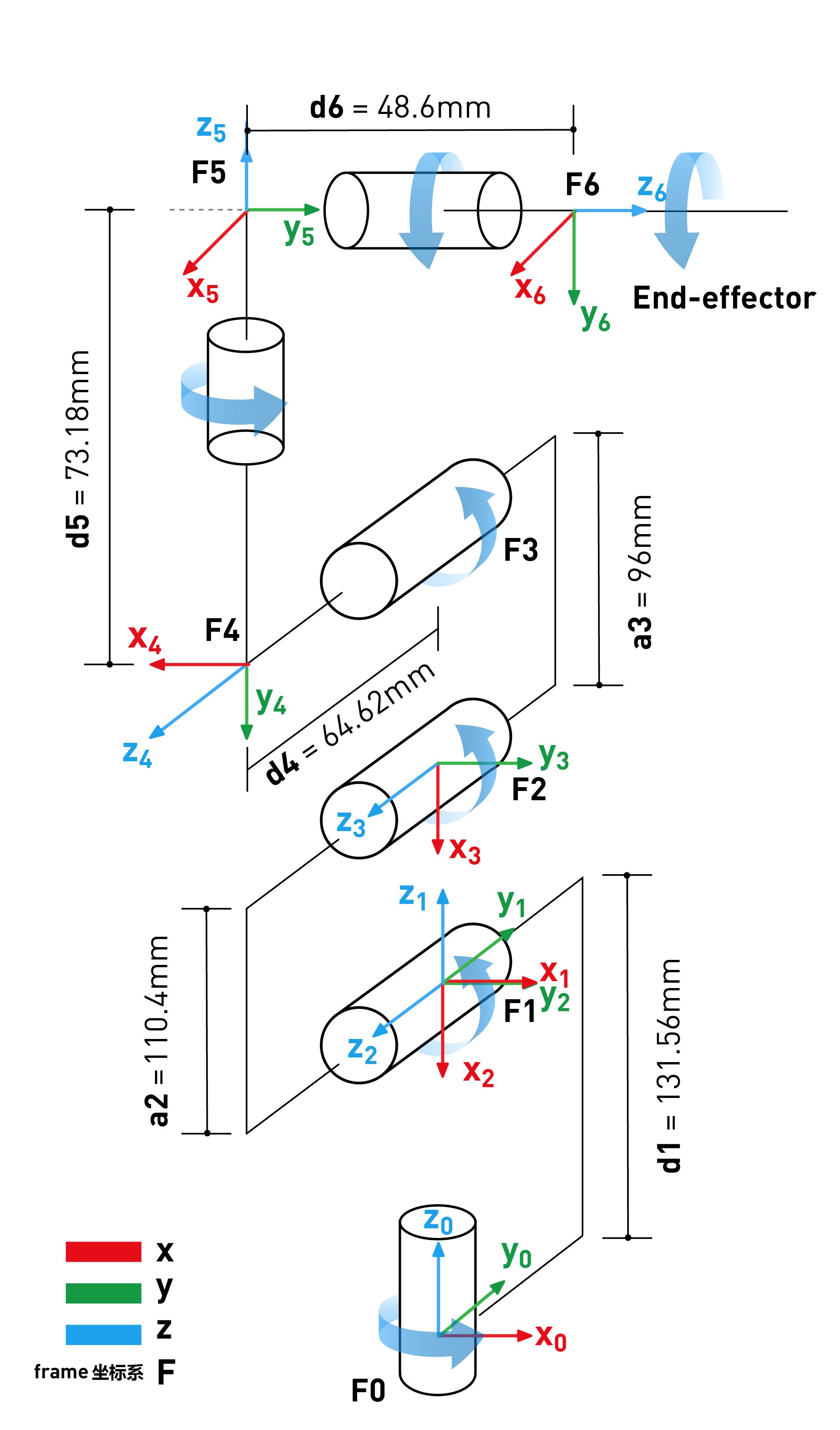
myCobot DH parameter
| Joint | alpha | a | d | theta | offset |
|---|---|---|---|---|---|
| 1 | 0 | 0 | 131.56 | theta_1 | 0 |
| 2 | PI/2 | 0 | 0 | theta_2 | -PI/2 |
| 3 | 0 | -110.4 | 0 | theta_3 | 0 |
| 4 | 0 | -96 | 64.62 | theta_4 | -PI/2 |
| 5 | PI/2 | 0 | 73.18 | theta_5 | PI/2 |
| 6 | -PI/2 | 0 | 48.6 | theta_6 | 0 |