Knowledge preparation
- Before entering the case, it is required to have the basic ability to use Python code, otherwise you may not understand the logic of the code, resulting in twice the effort with half the effort. At the same time, it is required to understand the general process of pymycobot controlling the movement of the manipulator. If you have not used pymycobot, you can simply refer to the following tutorials: pymycobot API reference documents、pymycobot course。
- Since the implementation of the case is based on ROS, you need to briefly understand some working principles of ROS before entering the tutorial. You can simply refer to the tutorial:ROS Official introduction。
Precautions
- The password in the image is 123
- The vision. Launch file must be opened between programs.
- The name of the manipulator in the virtual image should be consistent with the port value in the launch / vision. Launch file.
- For aruco code cases, the offset may need to be adjusted according to the actual situation.
- Viewable files of objects recognized by the picture recognition model: ~ / catkin mycobot/src/mycobot/mycobot ai/scripts/labels.json。
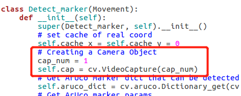
If the computer with the camera turned on comes with it, you need to adjust the parameters of turning on the camera in the program:cap_num,it can be modified to 0 or 1.
The color recognition and picture recognition cases are modified as follows:

- The aruco code identification case is modified as follows:
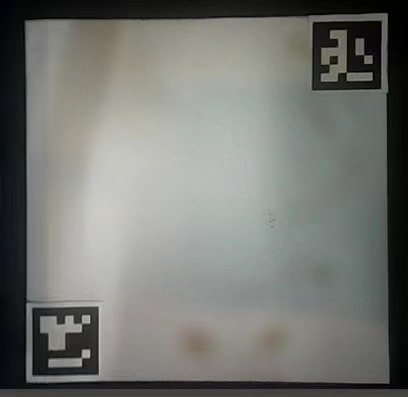
- Color and image recognition of the QR code position must be in accordance with the following picture, paste the correct
1 Suction pump connection
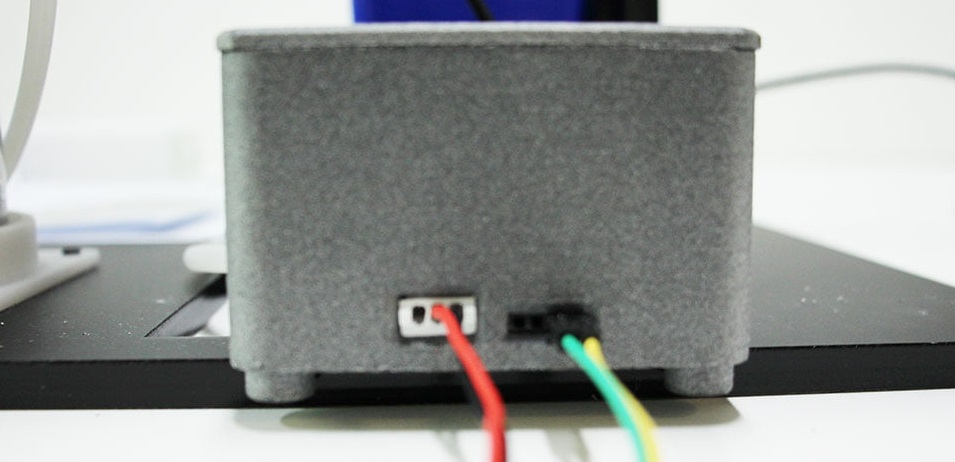
- As shown in the above figure, use the building block key to carry the suction pump to the head of the mechanical arm, and connect the bottom of the mechanical arm and the suction pump box through two DuPont wires
- Note: the bottom of the manipulator is the interface connecting 2 and 5, and the suction pump box is the two holes on the far right If the connection is wrong, it is easy to burn the M5 at the bottom of the manipulator!!!
Code implementation
ext, we will use the code to feel the use of the suction pump.
At mycobot_ In the ROS project, there is a mycobot_ AI package. Some actions of the manipulator have been encapsulated in the script in the package, including the use of suction pump. Therefore, you only need to inherit the class when you create it.
At mycobot_ In the ROS project, a use case of suction pump is given. The use of suction pump can be realized only after the required equipment is connected and operated. Please complete the connection of the device by yourself. Next, we will briefly describe how to run the case.
ls /dev/ttyUSB*   # View manipulator equipment name
sudo chmod 777 /dev/ttyUSB0  # Give permission to the viewed device (assuming that the viewed device name is / dev / ttyUSB0)
roslaunch <ros-workspace>/src/mycobot/mycobot_ai/launch/vision.launch  # Before starting the file, you need to modify the port value in the file
python <ros-workspace>/src/mycobot/mycobot_ai/script/pump.py  # Run the suction pump program
Modify the contents in vision. Launch, as shown in the following figure. Modify the default value of port to be consistent with the viewed manipulator equipment name. If it is not modified, the vision. Launch may fail to start.
2 Calibrate camera
It is not difficult to know the importance of the accuracy of the camera to the image recognition program. In order to ensure that the camera will not have serious image distortion, you can shoot the chess board through the camera, and calculate the camera matrix and distortion coefficient of the camera through the captured chessboard image. The camera calibration can be completed by loading the calculated camera matrix and distortion coefficient.
Of course, due to the use of a flat camera, the tutorial does not load calibration parameters. If you feel that calibration is troublesome, you can skip.
2.1 Generate an international chessboard chart
Prepare an all black picture of 630*890 and rename it to 3a4.bmp. Run the following program to get a picture of a chess board.
#!/usr/bin/env python3

"""Generate chess board picture"""

import os
import cv2


path = os.path.join(os.path.dirname(__file__), "3a4.bmp")
print(path)

frame = cv2.imread(path)
row, col, nc = frame.shape

width_of_roi = 90
# Here is the processing of all black pictures, which are separated in black and white zh
for j in range(row):
    data = frame[j]
    for i in range(col):
        f = int(i / width_of_roi) % 2 ^ int(j / width_of_roi) % 2
        if f:
            frame[j][i][0] = 255
            frame[j][i][1] = 255
            frame[j][i][2] = 255
cv2.imshow("", frame)
cv2.waitKey(0) & 0xFF == ord("q")
cv2.imwrite(os.path.join(os.path.dirname(__file__), "1.png"), frame)
2.2 Take chessboard pictures
Display the chessboard pictures on the computer and take multiple chessboard pictures through the camera.
#!/usr/bin/env python3

"""
This is an auxiliary file to help calibrate the camera.

It will call the camera, get the picture and display it in real time.

You can enter any value in the console to save the picture.
"""

import os
import cv2
import threading


if_save = False
# Set the camera number (due to different computer models, the number assigned to the USB camera may be different, usually 0 or 1)
cap_num = int(input("Input the camare number:"))
# Set the name of the stored picture to 1, which means that it is accumulated and stored from 1. For example: 1.jpg, 2.jpg, 3.jpg.....
name = int(input("Input start name, use number:"))

cap = cv2.VideoCapture(cap_num)
dir_path = os.path.dirname(__file__)


def save():
    global if_save
    while True:
        input("Input any to save a image:")
        if_save = True

# Start the thread for camera shooting
t = threading.Thread(target=save)
# Set to run asynchronously
t.setDaemon(True)
t.start()

while cv2.waitKey(1) != ord("q"):
    _, frame = cap.read()
    if if_save:
        # Set the name to the current path, otherwise the storage location will change due to the running environment
        img_name = os.path.join(dir_path,str(name)+".jpg")
        # Store pictures
        cv2.imwrite(img_name, frame)
        print("Save {} successful.".format(img_name))
        name += 1
        if_save = False
    cv2.imshow("", frame)
2.3 Obtain the camera matrix and distortion coefficient
Opencv has its own camera calibration function, which automatically generates the camera matrix and distortion coefficient we need by identifying the grid in the chessboard. Here we just need to make sure that the pictures taken in the second step can be recognized. It doesn't matter if we all recognize the failure. We just need to repeat the second step again. Of course, if you don't want to repeat the second and third steps in such trouble, you can directly skip the second step,
In the third step, when calling the calibration_camera function, set the cap_num parameter, that is, the camera number, and conduct real-time processing to obtain the camera and distortion coefficient. For detailed instructions, you can carefully read the comments in the code.
#!/usr/bin/env python3
import os
import glob
import numpy as np
import cv2 as cv
from pprint import pprint


def calibration_camera(row, col, path=None, cap_num=None, saving=False):
    """Calibrate camera

    Parameter Description:
        row (int): the number of rows in the grid.
        col (int): the number of columns in the grid.
        path (string): the location where the calibration picture is stored.
        cap_num (int): indicates the number of the camera, usually 0 or 1
        saving (bool): whether to store the camera matrix and distortion coefficient (. npz)
    """

    # Termination criteria / failure criteria
    criteria = (cv.TERM_CRITERIA_EPS + cv.TERM_CRITERIA_MAX_ITER, 30, 0.001)
    # Prepare object points, such as (0,0,0), (1,0,0), (2,0,0) ....,(6,5,0)
    obj_p = np.zeros((row * col, 3), np.float32)
    obj_p[:, :2] = np.mgrid[0:row, 0:col].T.reshape(-1, 2)
    # Groups are used to store object points and image points from all images.
    obj_points = []  # The position of 3D points in the real world.
    img_points = []  # Position of 2D point in the picture.

    gray = None

    def _find_grid(img):
        # Use parameters outside the function
        nonlocal gray, obj_points, img_points
        # Convert picture to gray picture
        gray = cv.cvtColor(img, cv.COLOR_BGR2GRAY)
        # Look for the corner of the chessboard
        ret, corners = cv.findChessboardCorners(gray, (row, col), None)
        # If found, the processed 2D points and 3D points are added
        if ret == True:
            obj_points.append(obj_p)
            corners2 = cv.cornerSubPix(gray, corners, (11, 11), (-1, -1), criteria)
            img_points.append(corners)
            # Draw and show the corner found in the picture
            cv.drawChessboardCorners(img, (row, col), corners2, ret)

    # It is required that you must select one of image calibration or camera real-time capture calibration
    if path and cap_num:
        raise Exception("The parameter `path` and `cap_num` only need one.")
    # Picture calibration
    if path:
        # Get all pictures in the current path
        images = glob.glob(os.path.join(path, "*.jpg"))
        pprint(images)
        # Process each acquired picture
        for f_name in images:
            # Read picture
            img = cv.imread(f_name)
            _find_grid(img)
            # Show pictures
            cv.imshow("img", img)
            # Picture display wait for 0.5s
            cv.waitKey(500)
    # Camera real-time capture calibration
    if cap_num:
        # Turn on the camera
        cap = cv.VideoCapture(cap_num)
        while True:
            # Read every picture after the camera is turned on
            _, img = cap.read()
            _find_grid(img)
            cv.imshow("img", img)
            cv.waitKey(500)
            print(len(obj_points))
            if len(obj_points) > 14:
                break
    # Destroy display window
    cv.destroyAllWindows()
    # The camera matrix and distortion coefficient are obtained by calculating the obtained 3D points and 2D points
    ret, mtx, dist, rvecs, tvecs = cv.calibrateCamera(
        obj_points, img_points, gray.shape[::-1], None, None
    )
    print("ret: {}".format(ret))
    print("matrix:")
    pprint(mtx)
    print("distortion: {}".format(dist))
    # Decide whether to store the calculated parameters
    if saving:
        np.savez(os.path.join(os.path.dirname(__file__), "mtx_dist.npz"), mtx=mtx, dist=dist)

    mean_error = 0
    for i in range(len(obj_points)):
        img_points_2, _ = cv.projectPoints(obj_points[i], rvecs[i], tvecs[i], mtx, dist)
        error = cv.norm(img_points[i], img_points_2, cv.NORM_L2) / len(img_points_2)
        mean_error += error
    print("total error: {}".format(mean_error / len(obj_points)))

    return mtx, dist


if __name__ == "__main__":
    path = os.path.dirname(__file__)
    mtx, dist = calibration_camera(8, 6, path, saving=True)
    # Set whether the calculated parameters need to be tested
    if_test = input("If testing the result (default: no), [yes/no]:")
    if if_test not in ["y", "Y", "yes", "Yes"]:
        exit(0)

    cap_num = int(input("Input camera number:"))
    cap = cv.VideoCapture(cap_num)
    while cv.waitKey(1) != ord("q"):
        _, img = cap.read()
        h, w = img.shape[:2]
        # Camera calibration
        dst = cv.undistort(img, mtx, dist)
        cv.imshow("", dst)
2.4 Load camera matrix and distortion factor
"""Load calibration parameters to calibrate the camera."""

import os
import numpy as np
import cv2 as cv


if __name__ == "__main__":
    # Load calibration parameters
    load = np.load(os.path.join(os.path.dirname(__file__), "mtx_dist.npz"))
    mtx = load["mtx"]
    dist = load["dist"]

    cap = cv.VideoCapture(0)
    while cv.waitKey(1) != ord("q"):
        _, img = cap.read()
        h, w = img.shape[:2]
        # Camera calibration
        dst = cv.undistort(img, mtx, dist, None)
        cv.imshow("", dst)
3 ROS building block model
To create a block model in ROS, you first need to open rviz, create a marker in rviz and set the marker Topic. Initialize a node and a marker in the python file, change the X and Y values of the marker and publish the changed marker to realize the displacement of the object block.
3.1 Start rviz
Start vision.launch in mycobot_ai package under ROS working directory to start rviz. The specific commands are as follows:
Before starting this command, make sure that the port value in vision. Launch is consistent with the actual manipulator name.
roslaunch <ros-workspace>/src/mycobot/mycobot_ai/launch/vision.launch
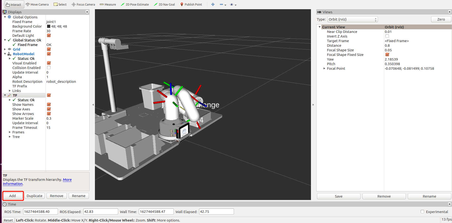
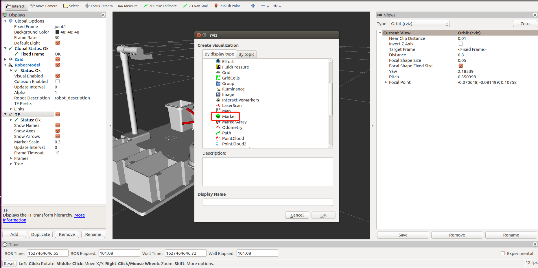
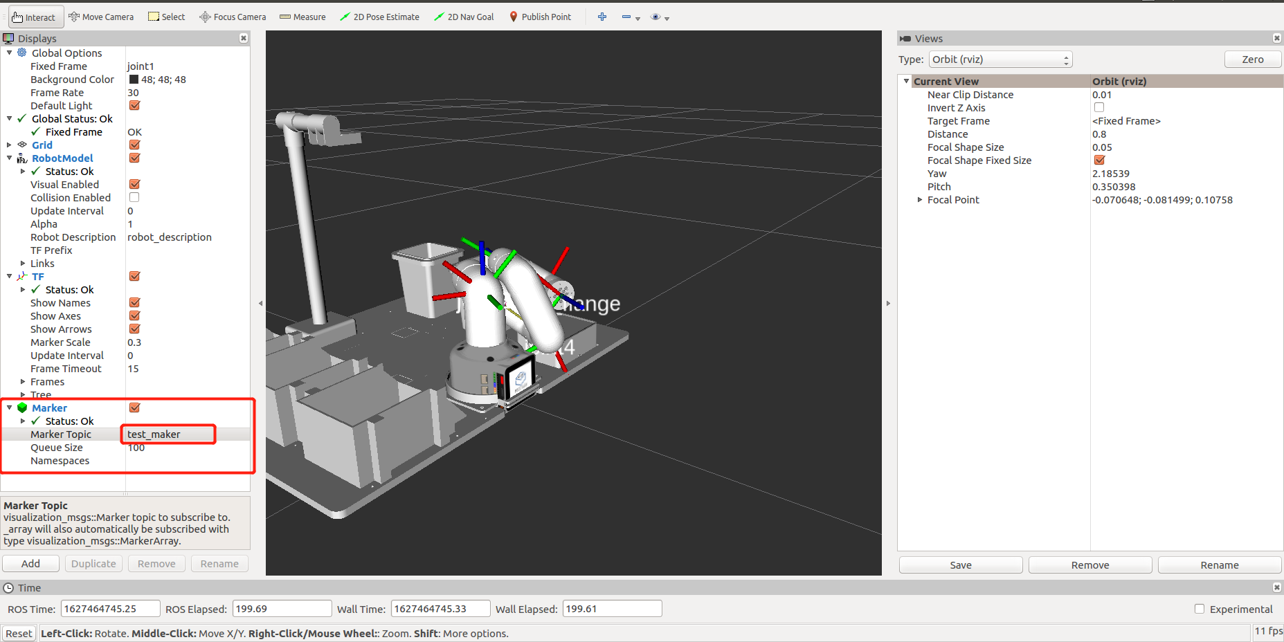
3.2 Create Box
In the rviz interface, click Add to add a marker and set the marker Topic to test_maker。 As shown in the figure below.
3.3 Block movement
After opening rviz and creating the block, open the command line terminal and run the following command line to see the yellow block moving in the model.
python <ros-workspace>/src/mycobot/mycobot_ai/scripts/send_marker.py

3.4 Code explanation
First, import some necessary ROS dependency libraries. Secondly, create a custom class and initialize a node, a publisher object and a marker class in the class initialization function. Finally, set some three-dimensional angles for the box to move in the model.
Here we will explain in detail some attribute values of the following marker objects:
type:representation type;
action:indicates an action of this marker;;
ns :indicates the name of this marker;
scale:indicates the actual size of the object block;
x、y、z:respectively indicate its length, width and height, and the unit is meter;
color :indicates the color of the block, and a indicates transparency;
r、g、b:respectively correspond to RGB of the color;
pose.position:indicates the coordinates of the actual position;
x、y、z:respectively represent the length, width and height of three-dimensional coordinates;
pose.orientation :represents a four-dimensional vector; For four-dimensional vectors, it doesn't matter if you don't have special requirements and don't understand them.
# encoding: utf-8

import rospy
import time
from visualization_msgs.msg import marker

class Send_marker(object):
    def __init__(self):
        # Inherit object class objects
        super(Send_marker, self).__init__()
        # Initialize a node. If the node is not created, the information cannot be published
        rospy.init_node("send_marker", anonymous=True)
        # Create a publisher to publish marker
        self.pub = rospy.Publisher("/test_marker", marker, queue_size=1)
        # Create a block model that marker uses to create
        self.marker = marker()
        # Configure its ownership relationship, and its coordinates are relative to / joint1.
        # /Joint1 represents the bottom of the manipulator in the model.
        self.marker.header.frame_id = "/joint1"
        # Set marker's name
        self.marker.ns = "test_marker"
        # Set the type of marker to be square
        self.marker.type = self.marker.CUBE
        # Set marker's action to add (marker without this name will add one)
        self.marker.action = self.marker.ADD
        # Set the actual size of marker, in m
        self.marker.scale.x = 0.04
        self.marker.scale.y = 0.04
        self.marker.scale.z = 0.04
        # Set marker's color, 1.0 for 255 (this represents a ratio conversion)
        self.marker.color.a = 1.0
        self.marker.color.g = 1.0
        self.marker.color.r = 1.0
        # Initialize marker's position and its four-dimensional attitude
        self.marker.pose.position.x = 0
        self.marker.pose.position.y = 0
        self.marker.pose.position.z = 0.03
        self.marker.pose.orientation.x = 0
        self.marker.pose.orientation.y = 0
        self.marker.pose.orientation.z = 0
        self.marker.pose.orientation.w = 1.0

    # Modify coordinates and publish marker
    def pub_marker(self, x, y, z=0.03):
        # Set marker's timestamp
        self.marker.header.stamp = rospy.Time.now()
        # Set marker's spatial coordinates
        self.marker.pose.position.x = x
        self.marker.pose.position.y = y
        self.marker.pose.position.z = z
        # Release marker
        self.pub.publish(self.marker)

    # Let marker happen y
    def run(self):
        time.sleep(1)
        self.pub_marker(0.1, -0.1)
        time.sleep(1)
        self.pub_marker(0.15, 0)
        time.sleep(1)
        self.pub_marker(0.15, -0.1)
        time.sleep(1)
        self.pub_marker(0.2, -0.1)
        time.sleep(1)
        self.pub_marker(0.15, -0.05)
        time.sleep(1)


if __name__ == '__main__':
    marker = Send_marker()
    marker.run()