1 OpenCV simple use
1.1 What is OpenCV
The full name of openCV is Open Source Computer Vision Library. It is an open source computer vision library of Intel (Intel), which consists of a series of C functions and C++ classes, and realizes many general algorithms in image processing and computer vision.
1.2 Installation and use of OpenCV
Windows
Open a console terminal (shortcut key Win+R, enter cmd, enter the terminal), enter the following command:
# The version numbers of the two need to be consistent, and version 4.6.0.66 is installed here
pip install opencv-python==4.6.0.66
pip install opencv-contrib-python==4.6.0.66
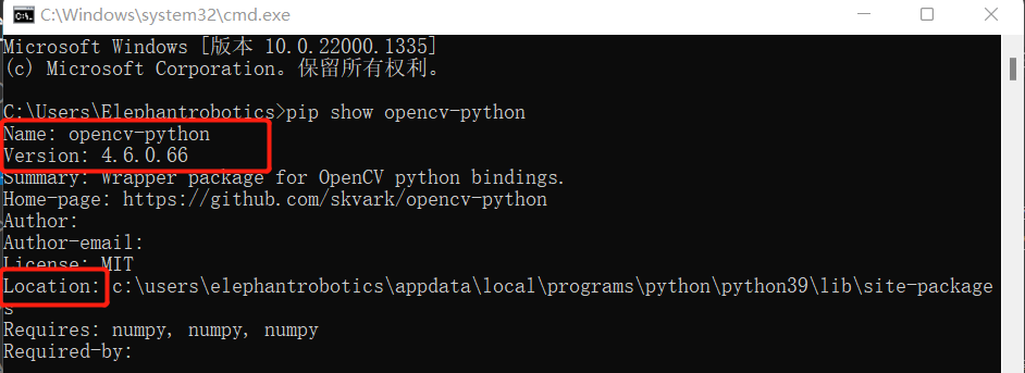
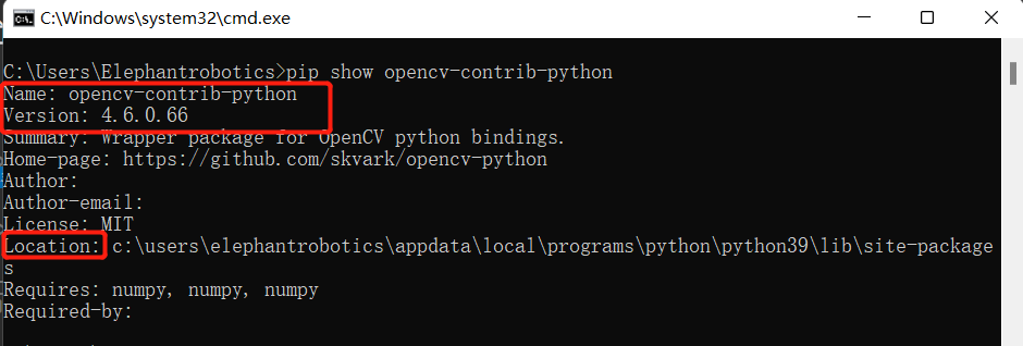
- Installation Verification
# You can also view other python libraries format: pip show library name
pip show opencv-python
pip show opencv-contrib-python
Linux
Open a console terminal (shortcut key Ctrl+Alt+T), enter the command:
# The version numbers of the two need to be consistent, and version 4.6.0.66 is installed here
pip install opencv-python==4.6.0.66
pip install opencv-contrib-python==4.6.0.66
simple use
import cv2
def openCamera():
    print('opencv version',cv2.__version__)
    print("Keyboard ESC to exit")

    cap = cv2.VideoCapture(0) # Linux
    # cap = cv2.VideoCapture(1) # Windows
    while cap.isOpened():
        sucess,frame = cap.read()
        if sucess:
            cv2.imshow("frame",frame)
            if cv2.waitKey(10)==27:
                break
    cap.release()
    cv2.destroyAllWindows()


if __name__=="__main__":
    openCamera()
2 End effector
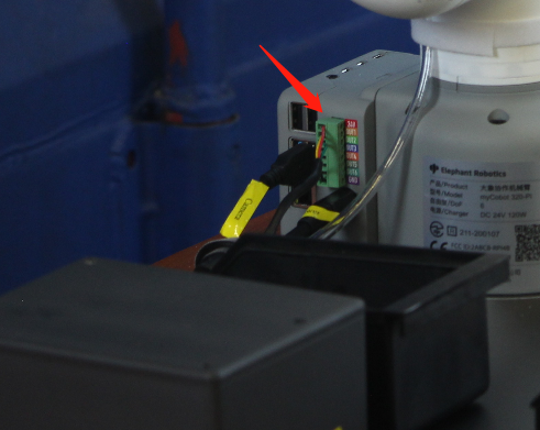
- myCobot Pro Single Head Suction Pump:
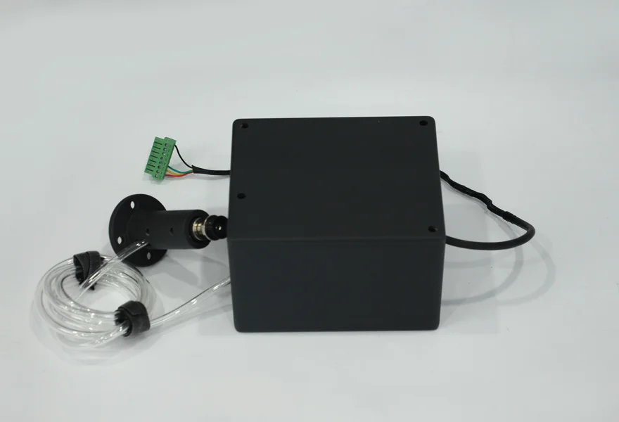
Connect the IO pin interface located on the right side of the robotic arm.
myCobot Pro Adaptive Gripper:
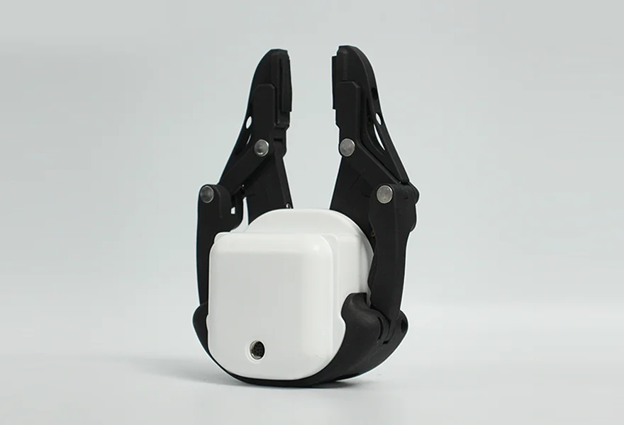
For specific connection details, please refer to the section on myCobot Pro Adaptive Gripper in the user manual or documentation.
Precautions
Please make sure that the product has been successfully connected according to the instructions
Please make sure the product is powered by the included adapter
Please make sure the power adapter is working properly
Please ensure the connection direction of the positive and negative poles
3 Coordinate Transformation and Calibration
3.1 Image coordinate transformation and calibration
3.1.1 four coordinate systems
In the development of robotic arm vision, an important preparatory work is to understand the meaning of the four coordinate systems, namely the camera coordinate system, the world coordinate system, the tool coordinate system and the base coordinate system.
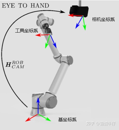
World coordinate system: The world coordinate system (world coordinate), also known as the measurement coordinate system, is a three-dimensional Cartesian coordinate system, based on which the spatial position of the camera and the object to be measured can be described. The position of the world coordinate system can be freely determined according to the actual situation. It can be understood as the earth coordinate system.
Camera coordinate system: The camera coordinate system (camera coordinate) is a three-dimensional rectangular coordinate system. The origin is located at the optical center of the lens. The x and y axes are respectively parallel to the two sides of the phase surface. The z axis is the lens optical axis and is perpendicular to the image plane.
Tool coordinate system: The tool coordinate system of the 6-axis or 7-axis collaborative arm. The origin is generally the center of the end of the robot arm, also called TCP (ToolCenterPoint). The Z axis coincides with the axis of the end and points to the direction of the end.
Base coordinate system: Dobots have a base coordinate system, and the default origin is the center point of the base of the collaborative arm.
3.1.2 camera calibration
The conversion of one coordinate system to another coordinate system mainly includes two aspects: position (origin) and attitude (XYZ axis). The transformation of the origin position is called translation, and the transformation of attitude is called rotation
3.1.3 Convert pixel coordinate system to base coordinate system
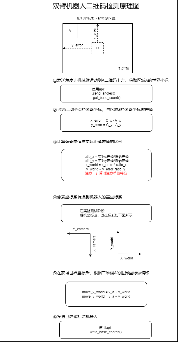
- Taking the visual recognition of a dual-arm robotic arm as an example
Obtain the value of the pixel center point in the image through the camera, and make a difference with the pixel center point of the starting point to obtain the pixel difference value. Transform the calculated pixel difference according to the scale set by the calibration. Converted to the difference in the world coordinate system, after the robot arm obtains the world coordinate of the starting point, it can obtain the actual world coordinate to be grasped according to the calculated difference of the world coordinate. Send the coordinates to the robotic arm to realize positioning and grabbing.
3.2 Coordinate Transformation and Calibration of Robotic Arm
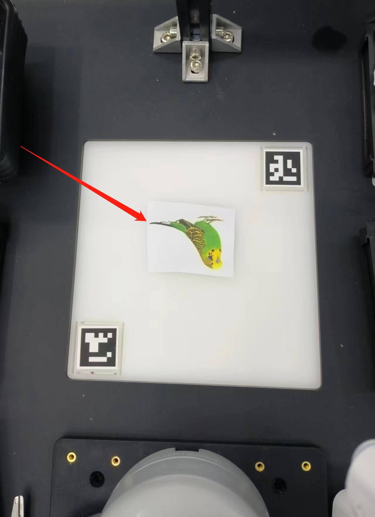
- The pixel distance M1 between the two arucos can be calculated by measuring the pixel points of the two arucos in the capture area, and the actual distance M2 of the two arucos can be measured, so that we can obtain the ratio of the pixel to the actual distance = M2/M1. We can calculate the pixel difference between the block and the center of the grabbing area from the picture, so that we can calculate the relative coordinates (x1, y1) of the block from the center of the grabbing area. Add the relative coordinates (x1, y1) to the relative coordinates (x2, y2) from the center of the grasping area to the robotic arm to obtain the relative coordinates (x3, y3) of the object to the robotic arm.
# Grab the coordinates of the center point relative to the robot arm
self.camera_x, self.camera_y = camera_x, camera_y

# The coordinates of the object relative to the robot arm can be set as:
self.c_x = self.c_y = 0, 0

# Pixel to Actual Ratio
self.ratio = 0

# Set the parameter function used to calculate the coordinates between the cube and the arm
def set_params(self, c_x, c_y, ratio):
    self.c_x = c_x
    self.c_y = c_y
    self.ratio = 320.0/ratio

# Get the position function, used to calculate the coordinates between the cube and the arm
def get_position(self, x, y):
    return ((y - self.c_y)*self.ratio + self.camera_x), ((x - self.c_x)*self.ratio + self.camera_y)
- Next, the program will call the setting parameter function set_params(), which is used to calculate and set the parameters for calculating the real coordinates between the object and the robot arm
detect.set_params(
                (detect.sum_x1+detect.sum_x2)/20.0,
                (detect.sum_y1+detect.sum_y2)/20.0,
                abs(detect.sum_x1-detect.sum_x2)/10.0 +
                abs(detect.sum_y1-detect.sum_y2)/10.0
            )
- Then the function get_position() will be called to calculate the real coordinates between the cube and mycobot.
real_x, real_y = detect.get_position(x, y)
- Finally, the real coordinates obtained will be slightly processed, and passed into the decide_move() function for subsequent robotic arm grabbing.
detect.decide_move(real_sx/20.0, real_sy/20.0, detect.color)
Precautions
opencv-python and opencv-contrib-python version libraries need to be consistent, and the version number is greater than 4.5.5.
When the camera does not automatically frame the recognition area correctly, you need to close the program, adjust the position of the camera, and move the camera to the left or right.
- If the command terminal does not show ok, and the color cannot be recognized, you need to move the camera slightly backward or forward, and the program can run normally when the command terminal shows ok.
- OpenCV color recognition will be affected by the environment, and the recognition effect will be greatly reduced in a darker environment.
- When performing yolov5 image recognition, in order to better recognize the picture, it is necessary to reverse the object in the recognition area**.