Electrical Interface of myCobot 280 Jetson Nano 2023
1 Introduction
1.1 Pedestal
A. Figure 2.1.7.2-1 shows the front ports and buttons of the pedestal:

Figure 2.1.7.2-1 Front view of the base
- ① Switch
- ② DC Interface of power
- ③ Functional Interface Group 1
- ④ Type C interface
- ⑤ HDMI interface
- ⑥ USB3.0
- ⑦ USB2.0
- ⑧ The network interface
- ⑨ Micro USB interface
1.2 Introduction to Interfaces on Pedestal
Notice: Functional interface group is Dupont interface of 2.54mm, and 2.54mm Dupont wire can be used externally.
- A. Table 2.1.7.2-1 shows the definition of each interface of the functional interface group 1.
| Label | Signal | Type | Function | Remark |
|---|---|---|---|---|
| GND | GND | p | GND | |
| 26 | GPIO26 | I/O | GPIO26 | |
| 19 | GPIO19 | I/O | GPIO19 | |
| 13 | GPIO13 | I/O | GPIO13 | |
| 06 | GPIO6 | I/O | GPIO6 | |
| 05 | GPIO5 | I/O | GPIO5 | |
| 00 | GPIO0 | I/O | GPIO0 | |
| GND | GND | p | GND | |
| 11 | GPIO11 | I/O | GPIO11 | |
| 09 | GPIO9 | I/O | GPIO9 | |
| 10 | GPIO10 | I/O | GPIO10 | |
| 3.3 | 3.3V | P | DC 3.3V | |
| 22 | GPIO22 | I/O | GPIO22 | |
| 27 | GPIO27 | I/O | GPIO27 | |
| 17 | GPIO17 | I/O | GPIO17 | PAD serial port occupation |
| GND | GND | p | GND | |
| 04 | GPIO4 | I/O | GPIO4 | |
| 03 | GPIO3 | I/O | GPIO3 | Occupied by SCL (serial clock line) in the I2C bus |
| NC | NC | - | - | Currently not supported |
| 3.3 | 3.3V | P | DC 3.3V | |
| 21 | GPIO21 | I/O | GPIO21 | |
| 20 | GPIO20 | I/O | GPIO20 | |
| 16 | GPIO16 | I/O | GPIO16 | |
| GND | GND | p | GND | |
| 12 | GPIO12 | I/O | GPIO12 | |
| GND | GND | p | GND | |
| 01 | GPIO1 | I/O | GPIO1 | |
| 07 | GPIO7 | I/O | GPIO7 | |
| 08 | GPIO8 | I/O | GPIO8 | |
| 25 | GPIO25 | I/O | GPIO25 | |
| GND | GND | p | GND | |
| 24 | GPIO24 | I/O | GPIO24 | |
| 23 | GPIO23 | I/O | GPIO23 | |
| GND | GND | p | GND | |
| 18 | GPIO18 | I/O | GPIO18 | PAD serial port occupation |
| NC | NC | - | - | Currently not supported |
| NC | NC | - | - | Currently not supported |
| GND | GND | p | GND | |
| 5V | 5V | P | DC 5V | |
| 5V | 5V | P | DC 5V |
Notice:
I/O: This function signal includes input and output combination.
When the single tube corner is set as the output terminal, it will output 3.3V voltage.
The source current of a single tube angle decreases with the increase of the number of pins, from about 40mA to 29mA.
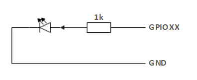
If a certain GPIO is set to the output mode and outputs a high level signal, the circuit connected to the LED is shown in Figure 2.1.7.2-2, and the LED will light up.
Figure 2.1.7.2-2
- In the case of using other functions, the IO function is unavailable, and the other function table of the function interface is shown in Figure 2.1.7.2-3.
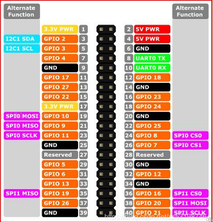
Figure 2.1.7.2-3
B. Power DC interface: It is a DC power socket with an outer diameter of 6.5 mm and an inner diameter of 2.0 mm; the 12V 5A DC power adapter provided by the manufacturer can be used to power the mycobot280.
C. Switch: After pressing it, the internal power turnes on, and the key lights up with a white light; when it is pressed again, the white light turns off, so does the internal power.
D. Type C interface: It can be used to connect and communicate with the PC.
E. HDMI interface: This interface is HDMI type A interface. If you want to display the robot operation interface, show the operation page to other equipment terminals by connecting the HDMI display interface.
F. USB2.0 interface: it is an interface for data connection conforming to the standard of main interface of 2.0; The USB port is used to copy program files and connect peripherals such as mouse and keyboard.
G. USB3.0 interface: it is an interface for data connection conforming to the standard of main interface of 3.0; The USB port is used to copy program files and connect peripherals such as mouse and keyboard.
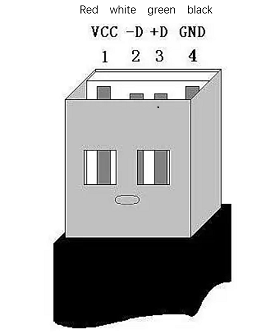
Figure 2.1.7.2-4
H. The network interface. They are (as shown in figure 2.1.7.2-5) ports for network data connection. Ethernet interfaces can be used for communication between a PC and a robotic system or for Ethernet communication with other devices.
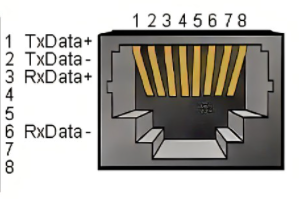
Figure 2.1.7.2-5
I. Micro USB interface: it is an interface for data connection conforming to the standard of main interface of 2.0; users can use the Android cable to copy program files.
2 Electrical Interface of the End
2.1 Introduction to the End
A. Figure 2.1.7.2-7 and Figure 2.1.7.2-8 show the side interface of the end:
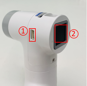
Figure 2.1.7.2-6 Side view of the end of the robotic arm
- ① Servo Interface
- ② Atom
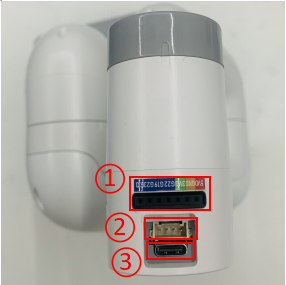
Figure 2.1.7.2-7 Side view of the end of the robotic arm
- ① Functional InterFace Group 2
- ② Grove
- ③ Type C
2.2 Terminal Electrical Ports
- A. The definitions of each interface of functional interface group 2 are shown in Table 2.1.7.2-2:
| Label | Signal | Type | Function | Remark |
|---|---|---|---|---|
| 5V | 5V | P | DC 5V | |
| GND | GND | P | GND | |
| 3V3 | 3V3 | P | DC 3.3V | |
| G22 | G22 | I/O | GPIO22 | |
| G19 | G19 | I/O | GPIO19 | |
| G23 | G23 | I/O | GPIO23 | |
| G33 | G33 | I/O | GPIO33 |
Notice:
I: input only.
I/O: This function signal includes input and output combination.
When the single tube corner is set as the output terminal, it will output 3.3V voltage.
The source current of a single tube angle decreases with the increase of the number of pins, from about 40mA to 29mA.
If a certain GPIO is set to the output mode and outputs a high level signal, the circuit connected to the LED is shown in Figure 2.1.7.2-8, and the LED will light up.
Figure 2.1.7.2-8

B. Type C interface: It can be used to communicate with PC and update firmware.
C. Grove interface : The definition of Grove interface is shown in Figure 2.1.7.2-9
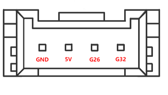
Figure 2.1.7.2-9 Grove
D. Servo Interface. It is used when expanding the gripper at the end, and currently supports the use of the matchable adaptive gripper.
E. Atom. Displaying 5X5 RGB LED (G27) and key function (G39).