Electrical Interface
1 base electrical interface
1.1 Base Introduction
The dock front connector and buttons are shown in Figure 1:
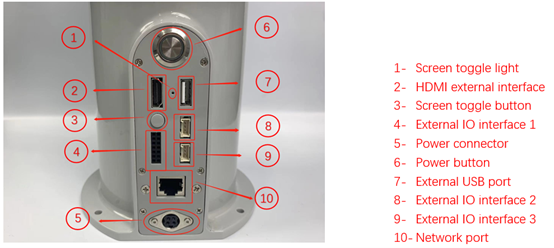
Figure 1-1 Front of the base
1.2 Chassis interface description
- Note: 14Pin function IO interface 1 is a 2.54mm DuPont interface, external can use 2.54mm DuPont line; function IO interface 2 and function IO interface 3 using Grove interface, as shown in Figure 1-2, 1-3:

Figure 1-2 Functional IO interface 2
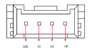
Figure 1-3 Functional IO interface 3
- A. For example, Table 1-1 defines the functions of IO interface 1.
| The label name | Signal name | function | remark |
|---|---|---|---|
| 3V3 | 3V3 | 3.3V power supply | |
| GND | GND | Motherboard power signal ground | |
| G17 | G17 | 3.3V-OUT-PNP output/3.3V-INT input | |
| G18 | G18 | 3.3V-OUT-PNP output/3.3V-INT input | |
| G27 | G27 | 3.3V-OUT-PNP output/3.3V-INT input | |
| G23 | G23 | 3.3V-OUT-PNP output/3.3V-INT input | |
| G22 | G22 | 3.3V-OUT-PNP output/3.3V-INT input | |
| G24 | G24 | 3.3V-OUT-PNP output/3.3V-INT input | |
| G10 | G10 | 3.3V-OUT-PNP output/3.3V-INT input | |
| G25 | G25 | 3.3V-OUT-PNP output/3.3V-INT input | |
| G9 | G9 | 3.3V-OUT-PNP output/3.3V-INT input | |
| G8 | G8 | 3.3V-OUT-PNP output/3.3V-INT input | |
| G11 | G11 | 3.3V-OUT-PNP output/3.3V-INT input | |
| G7 | G7 | 3.3V-OUT-PNP output/3.3V-INT input |
Table 1-1 IO Interface 1 Feature Table
- B. As Shown in Table 1-2, the definitions of each interface of functional IO interface 2 and functional IO interface 3 are defined.
| The label name | Signal name | function | remark |
|---|---|---|---|
| GND | GND | Motherboard power signal ground | |
| 5V | 5V | 5V power supply | |
| G2 | G2 | 3.3V-OUT-PNP output/3.3V-INT input | |
| G3 | G3 | 3.3V-OUT-PNP output/3.3V-INT input | |
| GND | GND | Motherboard power signal ground | |
| 5V | 5V | 5V power supply | |
| G5 | G5 | 3.3V-OUT-PNP output/3.3V-INT input | |
| G6 | G6 | 3.3V-OUT-PNP output/3.3V-INT input |
Table 1-2 IO interface 2/3 function table
Note: The other function tables about the functional interface are shown in Figure 1-4, and the IO function is not available with other functions:
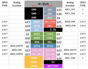
Figure 1-4
C. Power interface: DC power supply 24V, 9.2A.
D. Power button: with self-locking button, press on, the whole machine is powered on; Press Disconnect again, the whole machine is powered off.
E. Screen toggle button: Toggles the internal screen from the external screen display.
F. Screen switching indicator: When switching to external screen display, the green light is on; When switching to the internal screen display, the light is not lit.
G. HDMI external interface: (as shown in figure 1-5)This interface is an HDMI type A interface, the user can connect the HDMI display interface to display the operation page to other device terminals, press the screen toggle button can be used.
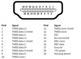
Figure 1-5 HDMI interface
- H. External USB interface: (as shown in figure 1-6)serial port bus standard 2.0 interface for data connection; The USB port is used to copy program files and connect peripherals such as mouse and keyboard.
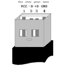
Figure 1-6 Defining USB ports
- I. Network port: (as shown in figure 1-7)ports for network data connection. Ethernet interfaces can be used for communication between a PC and a robot system or for Ethernet communication with other devices.
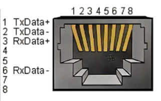
Figure 1-7 Network interface definition
2 robotic arm end electrical interface
Note: The electrical interface at the end of the mybuddy left and right arms is the same.
2.1 Introduction to the end of the robotic arm
- A. The side interface at the end of the picker is illustrated as shown in Figures 2-1 and 2-2:
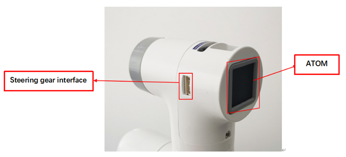
Figure 2-1 Side view of the end of the manipulator
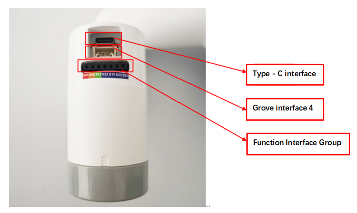
Figure 2-2 Side view of the end of the manipulator
2.2 Description of terminal electrical ports
A. Figure 2-3 shows the definition of each interface in a function interface group.
| Tag name | Signal name | Function | Note |
|---|---|---|---|
| 5V0 | 5V0 | Power supply, DC5V | |
| GND | GND | Motherboard power signal ground | |
| 3V3 | 3V3 | DC3.3 V power supply | |
| 22 | GPIO22 | 3.3 V-out-PNP output /3.3 V-int input | |
| 19 | GPIO19 | 3.3 V-out-PNP output /3.3 V-int input | |
| 23 | GPIO23 | 3.3 V-out-PNP output /3.3 V-int input | |
| 33 | GPIO33 | 3.3 V-out-PNP output /3.3 V-int input |
Figure 2-3 Functional interface group
B. Type C interface: used to communicate with PC and update firmware.
C. Grove interface 4: Figure 2-4 shows the definition of Grove interface 4
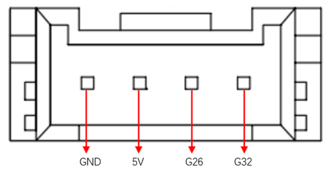
Figure 2-4 Grove port 4
D. Steering gear interface: used for expanding the end of the gripper, currently supporting the use of adaptive gripper.
E. Atom: For 5X5 RGB LED (G27) display and button function (G39)