Visual programming software RoboFlow
1 Use environment
Mycobot Pro 600 is developed and used based on raspberry pie drive and its own operating system, so it needs manipulator and related components to use in the process of use.
Display connection:
- monitor
- Micro HDMI to HDMI cable (distribution)
- mouse
- keyboard
PC connect:
- Office computer
- Network cable / WiFi environment (manipulator and PC are connected to the same WiFi)
- Remote connection software (VNC viewer, NoMachine)
Flat:
- Flat
- WiFi environment (manipulator and PC are connected to the same WiFi)
- Remote connection software (VNC viewer, NoMachine)
2 development environment
- 2.1 Development and use based on roboflow Roboflow operating system is the operating system of elephant cooperative robot, which provides human-computer interaction interface (its functions include coordinate control, angle control, IO control, track recording, gripper control, etc.). Since the roboflow operating system is already embedded in our manipulator system, users can use the screen or remote connection as the carrier for manual robot operation, programming and other operations.
2.2 Development and use based on ROS ROS is open source. It is a post operating system or secondary operating system for robot control. Through ROS, we can realize the simulation control of the manipulator in the virtual environment. We will realize the visualization of the manipulator through the rviz platform, and use a variety of ways to operate our manipulator; Plan and execute the action path of the manipulator through the moveit platform to achieve the effect of free control of the manipulator.After users Install ROS development environment ,users can read Use case and Use of moveit。
3 Roboflow first use teaching
3.1 prerequisite
Preconditions
- Check whether the mechanical arm is intact
- Install and fix the mechanical arm
- Connect the power adapter and provide the appropriate voltage
- Connect visualization device (monitor / PC remote connection)
- Connect keyboard and mouse (when connected to monitor)
- The emergency stop switch is on
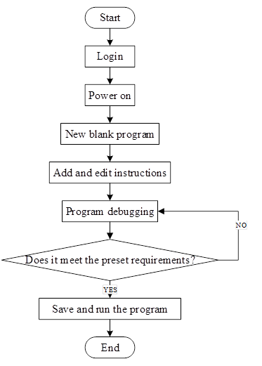
3.2 flow chart
The following is the program editing flow chart, as shown in Fig. 2-5.
3.3 Specific steps
3.3.1 Sign in
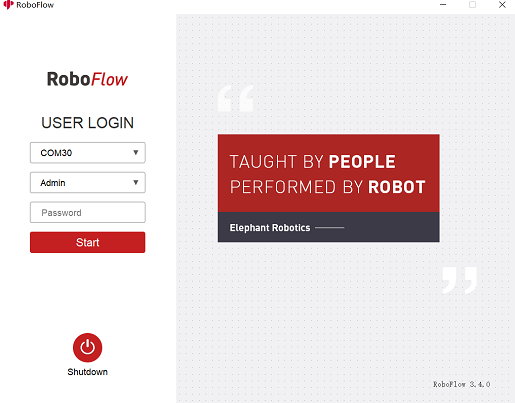
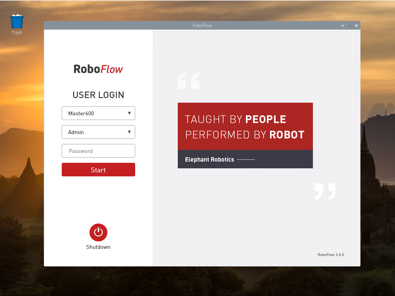
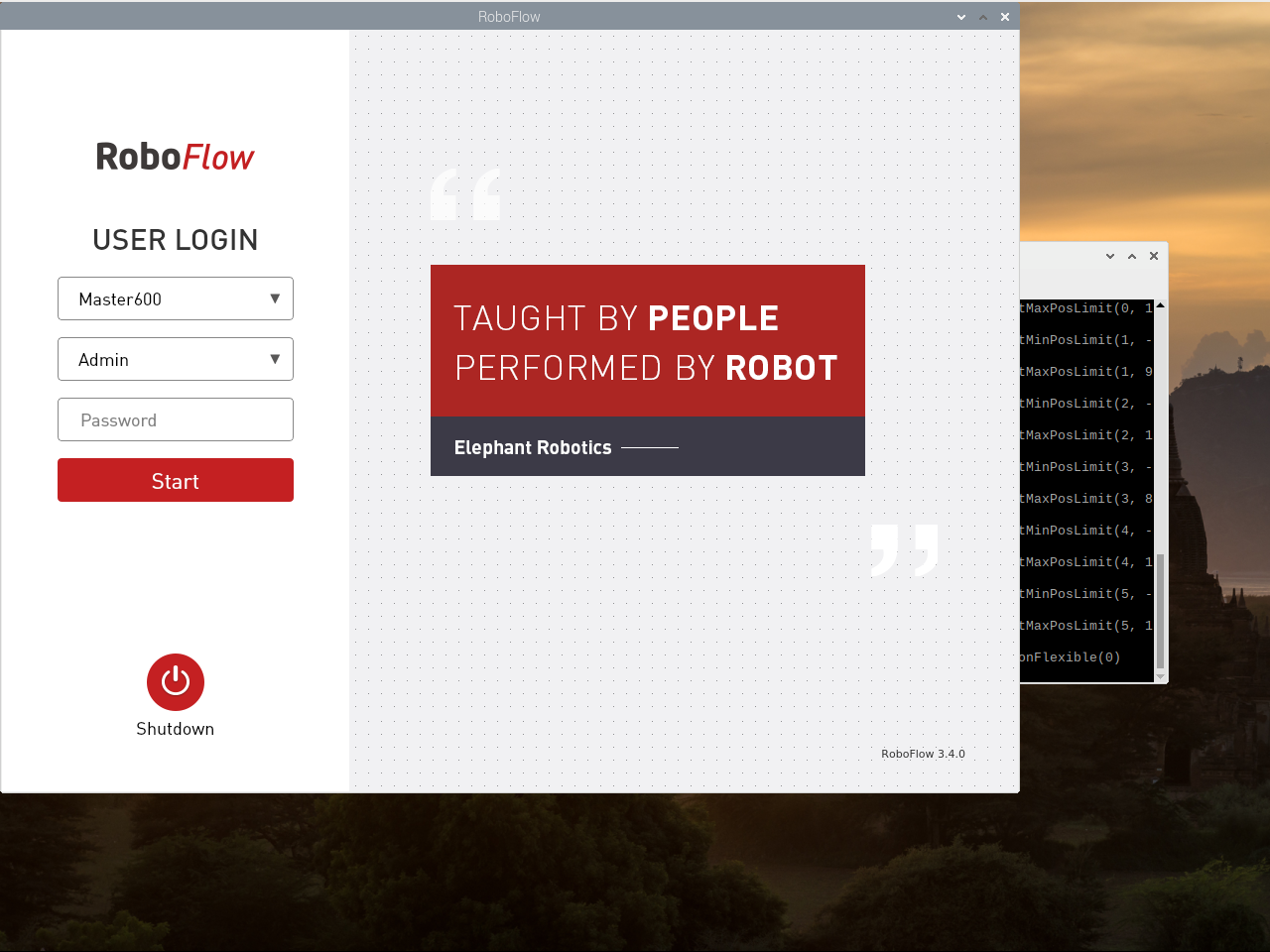
After the system starts successfully, the login interface of RoboFlow operating system is displayed, as shown in Figure 2-6.
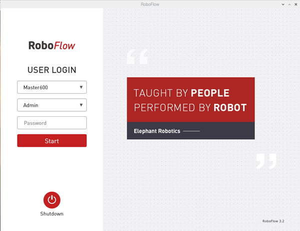
Select the login user name "Admin" or other administrator user name (only administrators are allowed to edit and debug programs), click the password box, and a pop-up window will appear as shown in Figure 2-7.
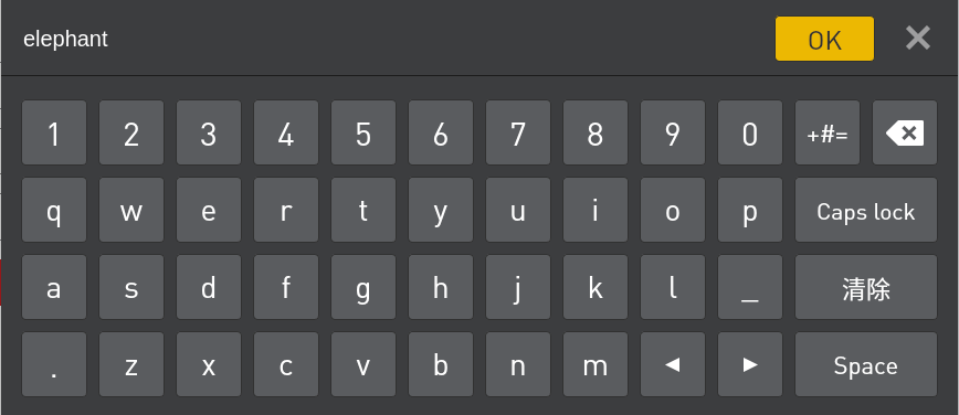
The default login password of the user name "Admin" is "elephant" (please enter the corresponding login password if you select other administrator user name), and enter the password and click "OK" to return to the page shown in Figure 2-6. Then click "Login" again to log in successfully.
3.3.2 Power on
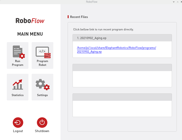
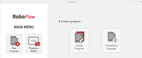
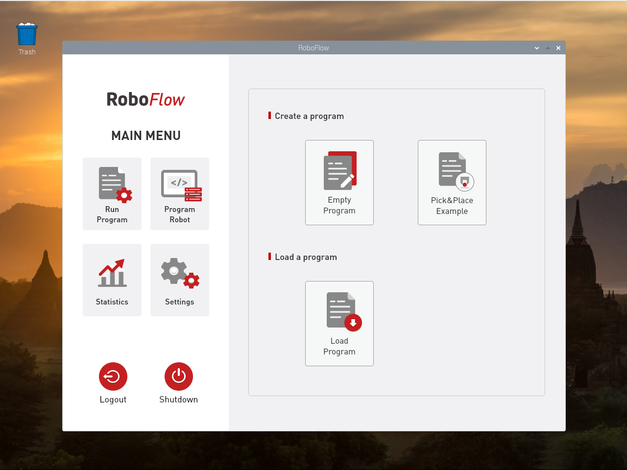
After successful login, the main menu is displayed, as shown in Figure 2-8.
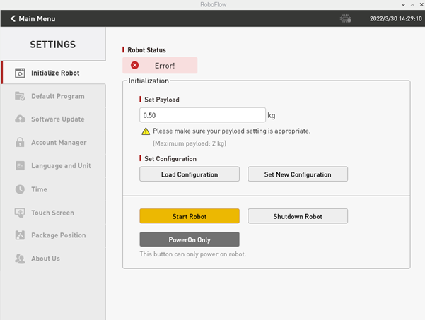
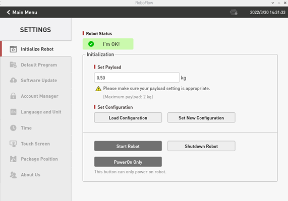
On the main menu interface, if you select "Configuration Center", the page shown in Figure 2-9 is displayed (not powered on yet).
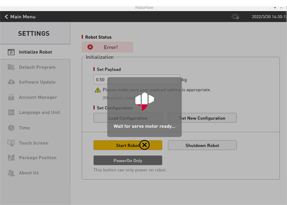
When ensuring that the emergency stop knob is not pressed, you can click the "Start Robot" button as shown in Figure 2-9. The interface will change at this point, and the "Being Powered On" icon will be displayed, as shown in Figure 2-10. If the power-on is successful, the "Normal State" will be displayed, as shown in Figure 2-11. If it fails, please check whether any steps are missing.
After completing the previous step, you can click the "< Main Menu" button in the Configuration Center to return to the main menu.
3.3.3 New blank program
As shown in Figure 2-12, click "Write Program" and then select "Blank Program".
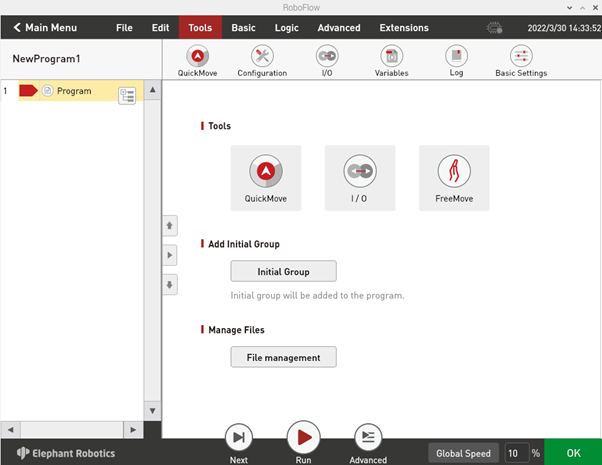
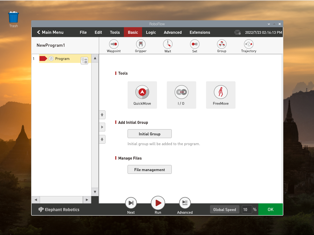
After the previous step, the program editing interface will be displayed, as shown in Figure 2-13.
3.3.4 Fast move
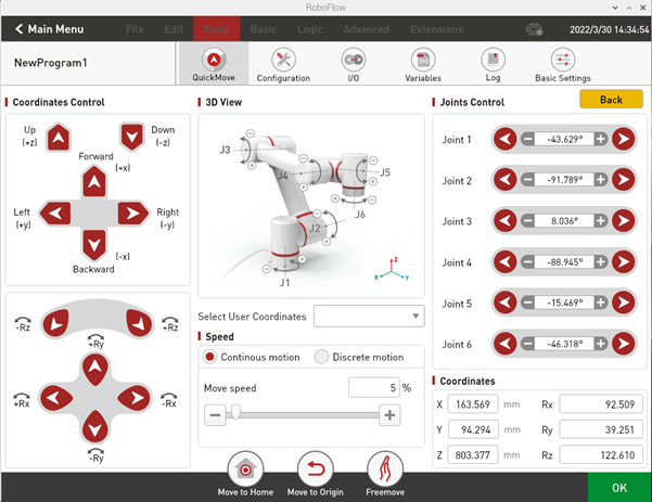
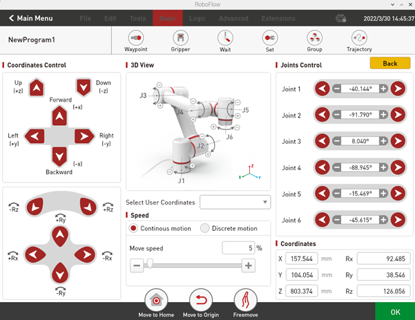
As shown in Figure 2-13, by clicking "Quick Moving", the window as shown in figure 2-14 will pop up. The control mode is divided into Cartesian coordinate control and joint control. The movement mode of moving can be continuous movement or step movement.
The Cartesian coordinate control refers to the linear movement on xyz-axis, and the robot can be controlled to move along the direction of Cartesian coordinate system by clicking the button corresponding to the direction of Cartesian coordinate system. Note that before using Cartesian control, you need to make sure that the second joint and the third joint shows a certain Angle.
Joint control provides the keys used by the operator to manually operate the robot with visual software and control the joint movement of the robot. The control keys of each joint are divided into two directions, and the Angle data of each axis can be seen.
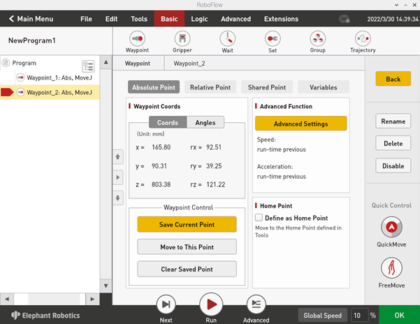
3.3.5 Add and edit instructions
As shown in Figure 2-15, there are two waypoints to add: absolute point instruction and teaching two points (that is, to use the quick moving tool to manually operate the robot, control the robot movement to a certain pose, return, click "Save the Current Point". The teaching steps of the two points are the same. If you need to verify the saved point, you can manually control the robot to move to the teaching point by long pressing the "Move to this point" button.)

3.3.6 Debugging program
As shown in Figure 2-16, in addition to the "Next" and "Run" functions provided in the program running control bar, by clicking the "Advanced Functions", you can enter the interface of more settings.
Among them, the "Next" function corresponds to the step by step execution of the program, and one click only runs one step, if you need to continue to run, click "Next". The "Run" function corresponds to automatically running the program once.
In "Advanced Functions", you can set the number of times the loop runs, or you can run the loop indefinitely. You can also control whether the program runs in automatic or manual mode. In automatic operation mode, you can use "Next", "Run", and cycle operation. On the interface shown in Figure 2-17, you can select "Manual Run Mode" and then select "Run" or "Infinite Loop" in cycle operation to enter the interface in manual run mode, as shown in Figure 2-20.
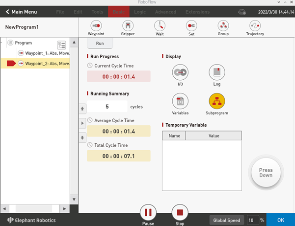
If you use manual mode to debug the program, you need to press on the "Press Down" button to continue running. If you release the button, the program pauses, and press it again to continue running.
3.3.7 Free movement
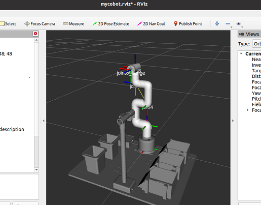
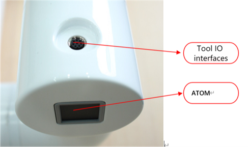
As shown in Figure 2-18, you can click the free movement button to make the robot arm enter the free movement mode, and at this time, you can move joint 1, joint 2 and joint 3, and if you need to move joint 4, joint 5 and joint 6, you need to press the ATOM button at the end, as shown in Figure 2-19.
3.4 Calibration
After we start the robot arm, we can see the RoboFlow login interface, which represents the normal startup of our Raspberry PI system
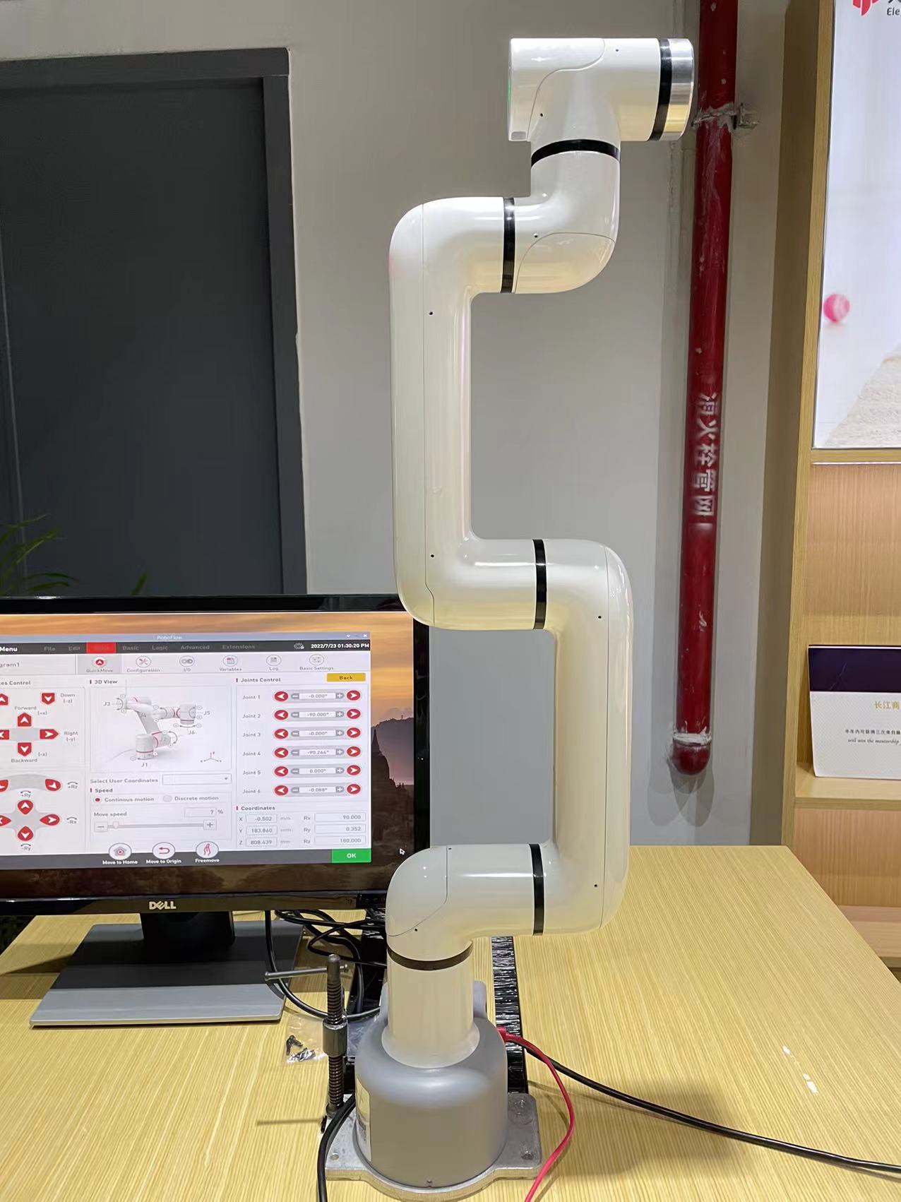
We need to move the manipulator by free movement, and the scale lines of each joint need to be aligned
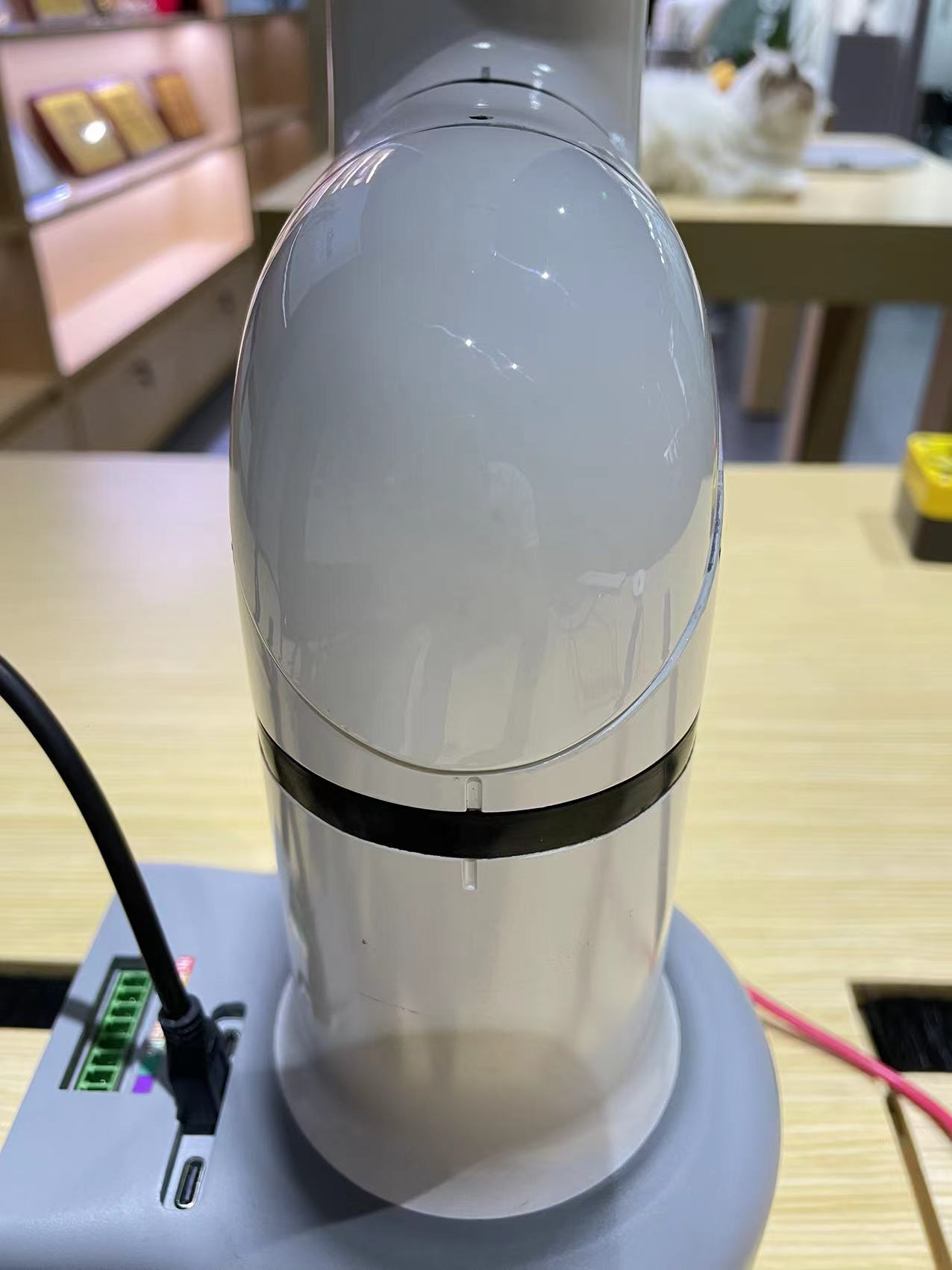
Adjust the alignment position of the six joints, and the manipulator will be in the following posture
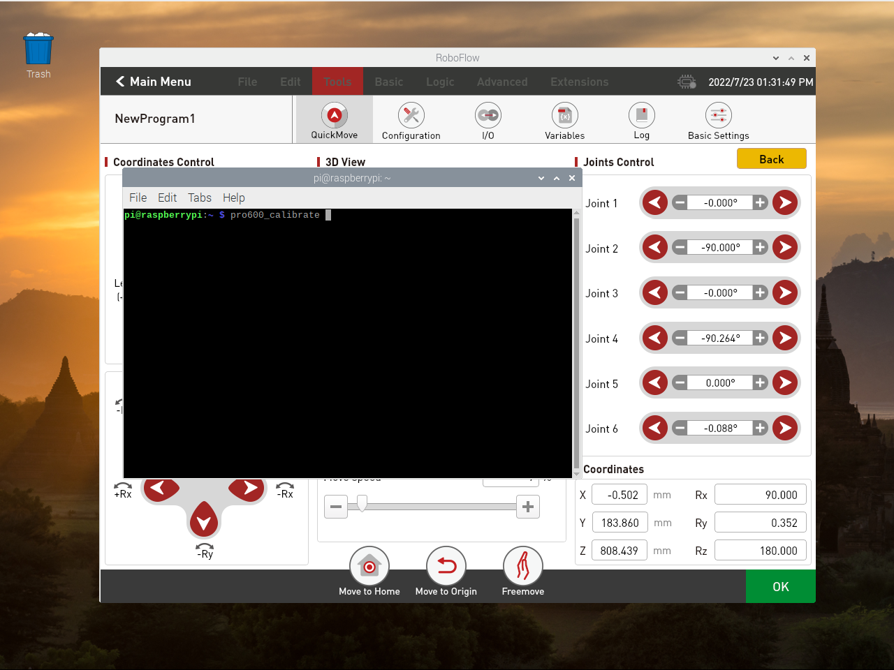
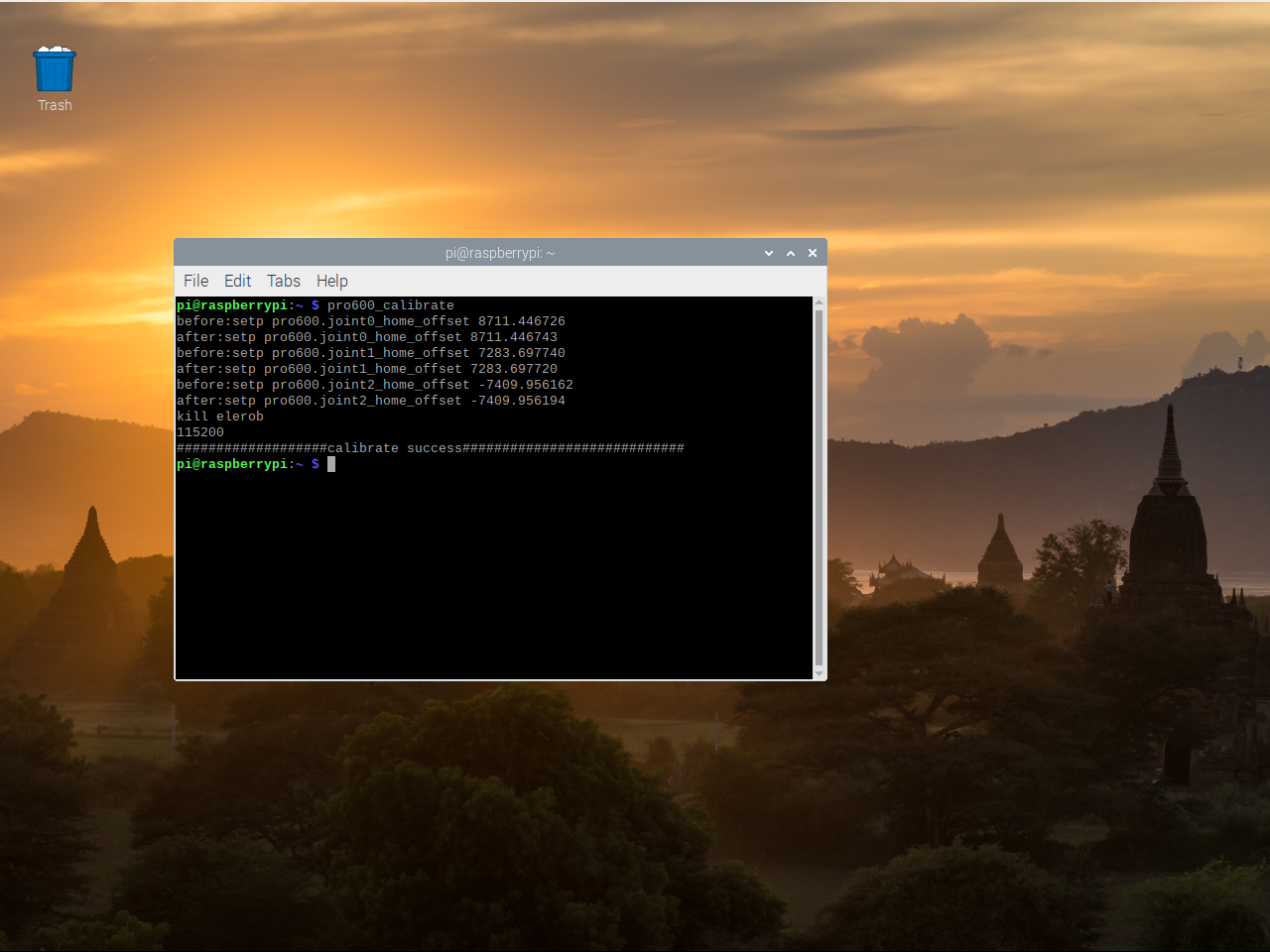
Move the mouse pointer to the top of the interface, click the Terminal Terminal in the upper left corner of the top menu bar, and enter PRO600_Calibrate into the Terminal (if there is no menu bar, the menu bar will unhide and display).

After the calibration is complete, the following information is displayed indicating that the calibration is successful: However, you can see that the RoboFlow software has been shut down and needs to be restarted.
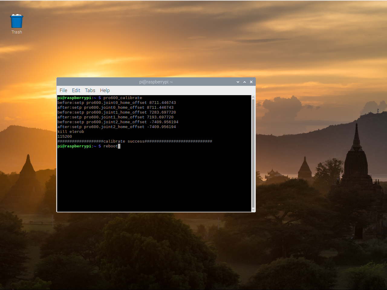
The first way to restart the software is to restart the manipulator system (wait for the system to restart).:
The second way to restart the software is to start it by typing instructions on the terminal:
Input:elerob -l(lowercase L)
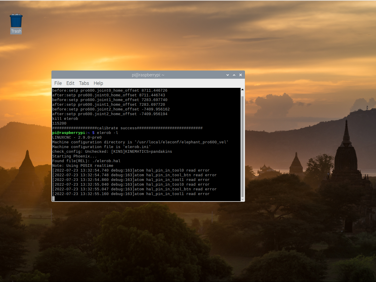
Then the Terminal Terminal in the upper left corner of the motor opens another Terminal interface
Input:cd RoboFlow && ./RoboFlow(注意此处均为小写的L)
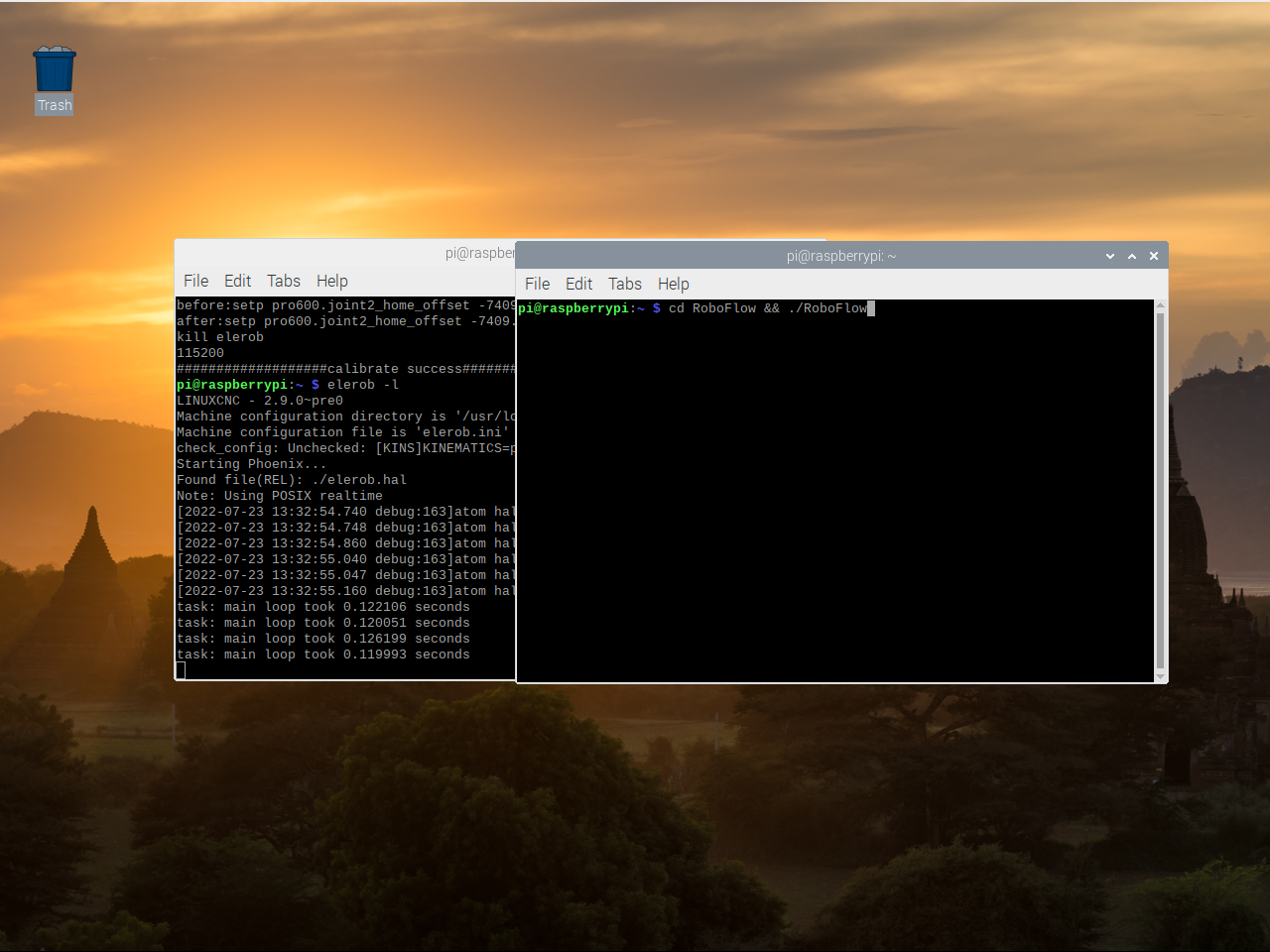
Finally, RoboFlow was successfully restarted
3.5 Drag Teaching
After logging in the RoboFlow software, we enter the main menu page and click Empty Program to create a new Program
Click on Basic

Click Trajectory to record a Trajectory
Set the speed to 70%(According to the actual situation) The recording mode is MoveJ(Recommended)

Click the red dot button in New Recording to start recording to begin track recording.
It can be combined in the recording FreeMove (3.3.7 FreeMove)dedrag track,or use QuickMove to record trajectory
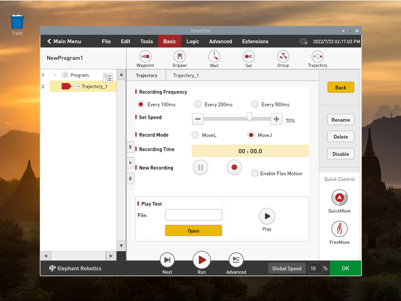
Click the red square point button in New Recording to start Recording to stop track Recording

Click Open to open the file and open the corresponding trace file

Select the default trajectory.txt file (the default trajectory file is trajectory.txt), and click OK
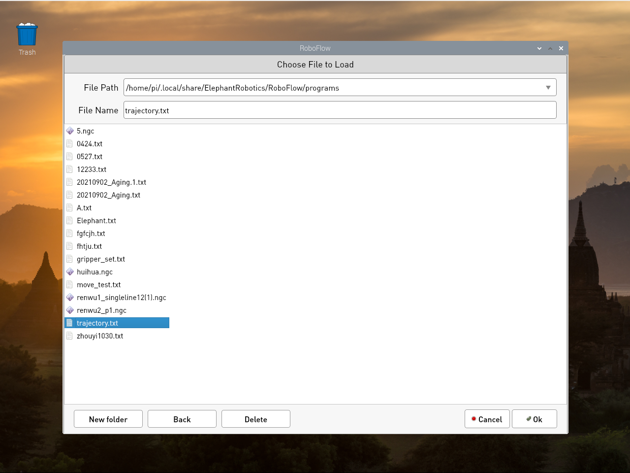
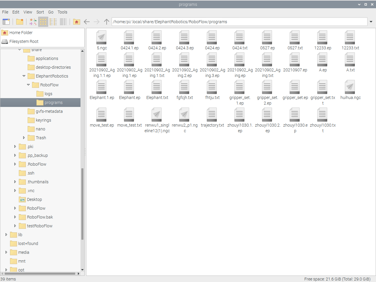
If you want to change the name of the recorded track file, you need to rename it in this folder (if you can't see the.local folder in the home directory, Ctrl + H will show the hidden file). Path:/home/pi/.local/share/ElephantRobotics/RoboFlow/programs
Click Play to Play the recorded track

This chapter mainly introduces the simple use of roboflow: how to log in and control the preparation of the manipulator, how to control the joints and coordinates. For detailed instructions, please refer to the roboflow operation and programming manual