PI version device
1 Hardware interface usage
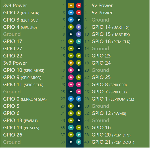
1.1 40PIN GPIO
Introduction
- GPIO:General-purpose input/output
- At present, all our Raspberry PI motherboards have a 40-pin GPIO head
Voltages
- Two 5V pins and two 3.3V pins are present on the board, as well as a number of ground pins (0V), which are unconfigurable. The remaining pins are all general purpose 3.3V pins, meaning outputs are set to 3.3V and inputs are 3.3V-tolerant.
Outputs
- A GPIO pin designated as an output pin can be set to high (3.3V) or low (0V).
Inputs
- A GPIO pin designated as an input pin can be read as high (3.3V) or low (0V). This is made easier with the use of internal pull-up or pull-down resistors. Pins GPIO2 and GPIO3 have fixed pull-up resistors, but for other pins this can be configured in software.
PWM (pulse-width modulation)
- Software PWM available on all pins
- Hardware PWM available on GPIO12, GPIO13, GPIO18, GPIO19
SPI
- SPI0: MOSI (GPIO10); MISO (GPIO9); SCLK (GPIO11); CE0 (GPIO8), CE1 (GPIO7)
- SPI1: MOSI (GPIO20); MISO (GPIO19); SCLK (GPIO21); CE0 (GPIO18); CE1 (GPIO17); CE2 (GPIO16)
IIC
- Data: (GPIO2); Clock (GPIO3)
- EEPROM Data: (GPIO0); EEPROM Clock (GPIO1)
Serial
- TX (GPIO14);RX (GPIO15)
Use python to control IO
    from pymycobot.mycobot import MyCobot
    from pymycobot import PI_PORT, PI_BAUD
    import time

    mc = MyCobot(PI_PORT, PI_BAUD)

    # Init
    GPIO.setmode(GPIO.BCM)
    GPIO.setup(20, GPIO.OUT)
    GPIO.setup(21, GPIO.OUT)
    # HIGH
    GPIO.output(20, 0)
    GPIO.output(21, 0)
    # WAIT
    time.sleep(2)
    # LOW
    GPIO.output(20, 1)
    GPIO.output(21, 1)
- GPIO interfaces are defined in the following table:
| Label | Signal | Type | Function | Remark |
|---|---|---|---|---|
| 5V | 5V | P | DC 5V | |
| 5V | 5V | P | DC 5V | |
| GND | GND | p | GND | |
| NC | NC | - | - | Currently not supported |
| NC | NC | - | - | Currently not supported |
| 18 | GPIO18 | I/O | GPIO18 | |
| GND | GND | p | GND | |
| 23 | GPIO23 | I/O | GPIO23 | |
| 24 | GPIO24 | I/O | GPIO24 | |
| GND | GND | p | GND | |
| 25 | GPIO25 | I/O | GPIO25 | |
| 08 | GPIO8 | I/O | GPIO8 | |
| 07 | GPIO7 | I/O | GPIO7 | |
| 01 | GPIO1 | I/O | GPIO1 | |
| GND | GND | p | GND | |
| 12 | GPIO12 | I/O | GPIO12 | |
| GND | GND | p | GND | |
| 16 | GPIO16 | I/O | GPIO16 | |
| 20 | GPIO20 | I/O | GPIO20 | |
| 21 | GPIO21 | I/O | GPIO21 | |
| 3.3 | 3.3V | P | DC 3.3V | |
| NC | NC | - | - | Currently not supported |
| 03 | GPIO3 | I/O | GPIO3 | |
| 04 | GPIO4 | I/O | GPIO4 | |
| GND | GND | p | GND | |
| 17 | GPIO17 | I/O | GPIO17 | |
| 27 | GPIO27 | I/O | GPIO27 | |
| 22 | GPIO22 | I/O | GPIO22 | |
| 3.3 | 3.3V | P | DC 3.3V | |
| 10 | GPIO10 | I/O | GPIO10 | |
| 09 | GPIO9 | I/O | GPIO9 | |
| 11 | GPIO11 | I/O | GPIO11 | |
| GND | GND | p | GND | |
| 00 | GPIO0 | I/O | GPIO0 | |
| 05 | GPIO5 | I/O | GPIO5 | |
| 06 | GPIO6 | I/O | GPIO6 | |
| 13 | GPIO13 | I/O | GPIO13 | |
| 19 | GPIO19 | I/O | GPIO19 | |
| 26 | GPIO26 | I/O | GPIO26 | |
| GND | GND | p | GND |
Notice:
I/O: This function signal includes input and output combination.
When the single tube corner is set as the output terminal, it will output 3.3V voltage.
The source current of a single tube angle decreases with the increase of the number of pins, from about 40mA to 29mA.
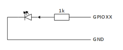
If a certain GPIO is set to the output mode and outputs a high level signal, the circuit connected to the LED is shown in Figure and the LED will light up.
- In the case of using other functions, the IO function is unavailable, and the other function table of the function interface is shown in Figure
1.2 Pedestal Introduction
A. Figure 2.1.5.2-1 shows the front ports and buttons of the pedestal:
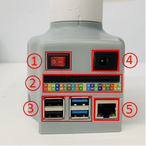
Figure 2.1.5.2-1 Front view of the base
- ① Switch
- ② Functional Interface Group 1
- ③ USB2.0 , USB3.0
- ④ DC Interface of power
- ⑤ The network interface
B. Figure 2.1.5.2-1 Showing the ports on the side of the base:
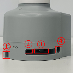
Figure 2.1.5.2-2 side of base
- ① SD card slot
- ② Type C interface
- ③ HDMI interface
- ④ Headphone jack
1.2 Introduction to Bottom Electrical Interfaces
A. Power DC interface: The myCobot280 is powered by a 6.5mm OD, 2.0mm OD, and a manufacturer's 12V 5A DC power adapter.
B. Switch: Red means switch,also means powering on, while O means powering off.
C. USB2.0 interface. Serial port with the standard of main line for 2.0 interface. The USB port is used to copy program files and connect peripherals such as mouse and keyboard.
D. USB3.0 port (blue) : The port that uses serial bus 3.0 for data connection. The USB port is used to copy program files and connect peripherals such as mouse and keyboard.
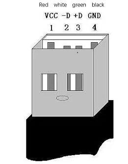
Figure 2.1.5.2-5
E. The network interface: Ports for network data connection, as shown in figure 2.1.5.2-5. Ethernet interfaces can be used for communication between a PC and a robot system or for Ethernet communication with other devices.
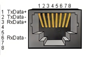
Figure 2.1.5.2-6
F. HDMI port: The HDMI D-type port connects with the monitor. HDMI port 2 has a priority, and HDMI port is recommended.
G. Type-C port: connecting to the PC.
H. SD card slot: The SD card can be inserted and removed. The size of the SD card is 32mm x 24mm x 2.1mm